3-1 AIR CLEANER AND INTAKE SILENCER
A new air cleaner with a high level in let tube, oval in shape, is used on the 1958 Buicks. Modified from the straight-ahead design of the 1957 air cleaner, the new in let tube is directed 15° to the right of the center line of the engine to prevent the direct entrance of dirt and to maintain low restriction characteristics. See Figure 3-1.
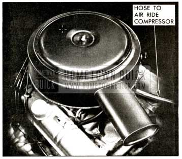
1958 Buick Air Cleaner
3-2 FUEL LINE
The synthetic rubber fuel lines used in 1957 will be continued in 1958, but will be suspended from the frame instead of attached to it. By suspending the lines, less heat, transferred from the exhaust system to the frame, is absorbed by the fuel. Thus, the temperature of the fu el is lower and any tendency toward vapor lock is reduced .
The air cleaner on all four-barrel carburetors is supported by two mounting tabs located at top of the carburetor air horn. (Figure 3-2.)
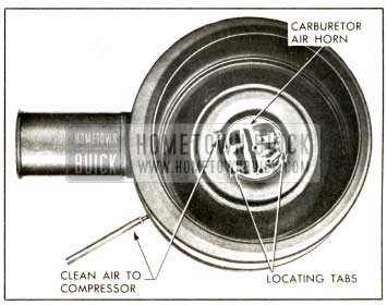
1958 Buick Air Cleaner Mounting
This eliminates the need for a front mounting bracket. The air cleaner used on cars equipped with air ride suspension has a hole located just above the air horn of the carburetor which is connected to the inlet of the air ride compressor. This allows clean air to be “drawn” from the air cleaner by the air compressor and eliminates in l et noise.
I MPORTANT: When the 4-barrel carburetor air cleaner is installed, it must be seated around (not on) the mounting tabs and the air inlet tube spaced away from the radiator hose and compressor (on air conditioner equipped cars) . Also on Air-Poise cars, the air compressor air inlet hose must be installed properly over the air cleaner outlet to prevent a possible air leak .
3-3 FUEL FILTER
The fuel filter or strainer is of the glass bowl type and is located in the line between the fuel pump and the carburetor and is basically the same type as used on 1 957 after jobs. The only change on the 1958 filter is the position of the fuel inlet and outlet. The filter is mounted on a separate bracket which is attached under one of the thermostat housing bolts. In this location, the bowl can be inspected or cleaned conveniently without removing the air cleaner.
The filter element has a large filtering area. It is of fine enough material to assure that any particles which pass through it are too small to interfere with the operation of the float needle and seat, and also too small to ca use clogging of the smallest passages in the carburetor. This element prevents the passage of water under ordinary conditions; however, water or other foreign matter should never be allowed to collect in the bowl until it reaches the lowest part of the filtering element. To prevent this possibility, the glass bowl should be visually inspected at each 1,000 mile Lubricare period and cleaned if necessary.
To clean the filter, remove the bowl and dump the contents. Soak the bowl in a good cleaning solvent to loosen any deposits. Visually inspect the filtering element and gasket; replace if necessary. Wipe the bowl clean with a clean cloth and reinstall, tightening finger tight.
After assembling the fuel filter, always start the engine and observe the filter carefully to make sure that the gasket is not leaking.
3-4 FUEL TANK
The same fuel tank is used on all series cars in 1958. However, three different filler necks are used . Series 40, 60, 50 and 70 use a filler which is a steel tube soldered into the tank. The Series 50 and 70 filler is longer than the Series 40 and 60 filler. The Series 700 cars use an adapter tube soldered into the tank with a hose extension to the filler.
The gas gauge tank unit is combined with the fuel outlet pipe and is relocated in the forward edge of the tank. It is not necessary to lower the fuel tank to replace this assembly. See Figure 3-3.
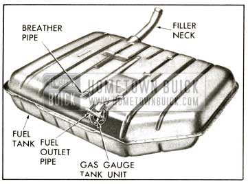
1958 Buick Fuel Tank
3-5 CARBURETOR
With the following exceptions, the two-barrel and four-barrel carburetors for 1958 are functionally unchanged. The Stromberg two-barrel will have a larger needle valve and seat and a spring loaded float. The Carter four-barrel and Rochester four-barrel will have a modification of the air horn to accommodate the new air cleaner and silencer.
Specifications for the 1958 carburetors will be covered in future BPS Bulletins. Listed below are the five carburetors and the car series they will be used on in 1958:
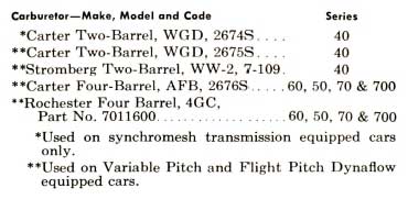
1958 Buick Carburetor Overview
3-6 THROTTLE LINKAGE
Throttle Linkage Adjustments
Throttle linkage adjustments are unchanged from those used on 1957 Buicks and are listed in Par. 3-9 of the 1957 Chassis Service Manual.
Stator Linkage Adjustment
Adjust stator linkage only after throttle link age adjustment has been made. The 1958 Variable Pitch Dynaflow stator linkage adjustment is the same as used on the 1957 Dynaflow.
The following is the procedure for adjusting stator linkage on cars equipped with Flight Pitch Dynaflow.
- Disconnect upper stator rod ball joint from stator lever on carburetor.
- With carburetor throttle set at hot idle position, adjust upper stator rod so that the ball joint at forward end will just slip freely into stator l ever while holding both stator l ever and rod in full rearward position.
- Short e n stator rod one turn to provide clearance at stop.
- Reconnect ball joint to stator lever and tighten nut.
3-7 EXHAUST SYSTEM
The dual exhaust system is standard on Series 70 and 700 and optional on 40, 60 and 50 Series.
Tailpipe
The 1958 Buick tailpipe outlets are located below the bottom level of the rear bumper face plate. These outlets are not visible, and bumper discoloration is reduced. See Figure 3-4.
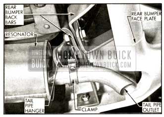
1958 Buick Tail Pipe Outlet
Tailpipe Hangers
The center tailpipe hanger, located above the rear axle, is a “U” shaped fabric hanger which is attached to the rear spring cross-member by two bolts. The tailpipe is clamped to the hanger with a conventional type strap. A new rear tailpipe hanger is bolted to the rear bumper back bar and attached to the tailpipe with a “U” shaped clamp. This must be adjusted so that proper clearance is maintained between the tailpipe outlet and the bumper. The complete exhaust system must be free from binds and interferences.
i am looking for a gas tank 57 buick special