SECTION 10-A – ELECTRICAL SPECIFICATIONS
10-1 BATTERY SPECIFICATIONS
Model: 560
10-2 GENERATING SYSTEM SPECIFICATIONS
- Generator
1958 Buick Generator Specifications
- Generator Regulator-Air Conditioning
1958 Buick Generator Regulator Specifications (Air Conditioner)
- Generator Regulator–Non Air
1958 Buick Generator Regulator Specifications (No Air Conditioner)
10-3 LIGHTING SYSTEM SPECIFICATIONS
- Headlamp Sealed Beam Unit
1958 Buick Headlamp Sealed Beam Unit
- Lamp Bulbs-Number
1958 Buick Lamp Bulbs Numbers
SECTION 10-B BATTERY
10-4 BATTERY
A new Delco-Remy battery, Model 560, is used in all 1958 Series. It is a 6 cell, 11 plates per cell, battery with a 70 ampere-hour rating.
The new battery has the same specifications as the 1957 Model, the only differences being in the dimensions of the batter y. The case of the 1958 battery will be narrower in width and longer in length.
SECTION 10-C GENERATING SYSTEM
10-5 GENERAL DESCRIPTION
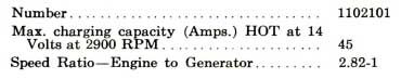
For 1958 the generator has been redesigned to obtain a greater ampere output. The field coils have been designed so as to increase both maximum and low speed output.
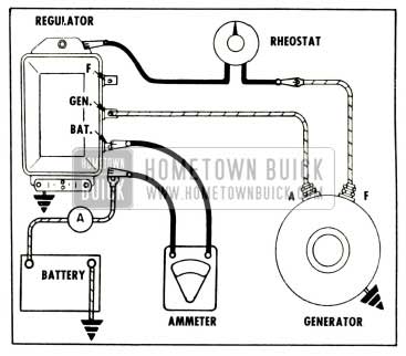
The generator regulator for 1958 will be much the same as 1957 with the exception of the use of two sets of contact points on the voltage control. A pictorial view of the generator system circuits with the voltage regul9tor with dual contact points is shown in Figure 10-1.
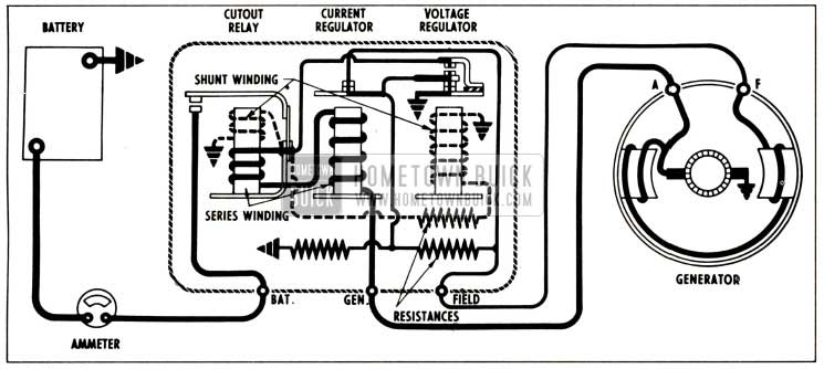
1958 Buick Generator System Circuits
10-6 GENERATOR
The increase in maximum output by the generator is accomplished by changing the number of field coil windings and the size of wire. Greater low speed output is accomplished by increasing the generator-to-crankshaft drive ratio from 2.4:1 to the new ratio of 2.82:1.
To insure longer life of the generator due to the increased need of higher field current, the 1958 generator will have longer life brushes, and ball bearings will be used at both ends of the armature. See Figure 10-2.
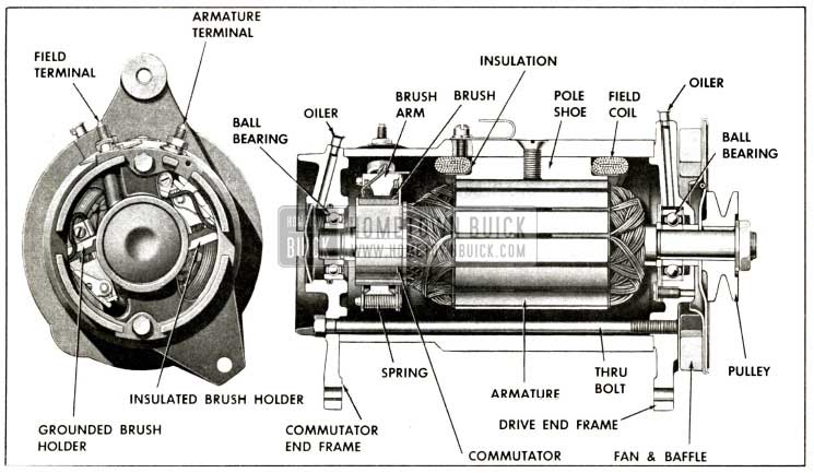
1958 Buick Generator Sectional View
On cars equipped with air conditioning, an air duct will be provided from the front of the engine compartment to an air inlet at the rear of the generator. This duct is designed to direct outside air to be circulated through the generator to permit a higher output under extreme operating conditions. This cooling air reduces resistance in the generator by allowing lower operating temperatures.
10-7 GENERATOR REGULATOR
Two sets of points are being used in the voltage control to accommodate the higher field current used on the newly designed generator. See Figure 10-3.
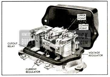
1958 Buick Generator Regulator
When the generator field requirements are high (relatively low car speed and high accessory load) the regulator operates on the lower set of contacts. When the field requirements are low (relatively high car speed and low load) the resistance inserted in the field circuit when the lower contacts open is not sufficient to control the generator voltage.
With a slight increase in voltage (.1 to .3 volts), the armature is pulled down to operate on the upper set of contact points. The generator field is then shorted out when the points close.
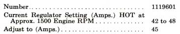
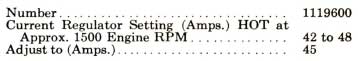
On cars equipped with air conditioning a different generator regulator with special temperature compensation at the current regulator will be used. This compensation is designed to take advantage of the additional cooling of the new generator by outside air. Due to this temperature compensation factor the two 1958 generator regulators are not interchangeable. Regulator and generator damage will result if regulators are interchanged.
10-8 PERIODIC INSPECTION AND TEST OF GENERATOR-ON CAR
lnspection Procedure
The inspection procedure for 1958 is similar to that used in 1957.
Testing Generator Output
After inspection is completed, it is advisable to test the generator output. Before making the following tests, however, make certain that the battery specific gravity is at least 1.215.
CAUTION: With the double contact voltage regulator, never ground the generator field while the field lead is connected to the regulator, as this would result in the burning of the voltage regulator upper contacts.
- Disconnect field lead from generator regulator “F” terminal and connect a field rheostat (25 ohm-25 watt) between this lead and ground. See Figure 10-4. Turn variable resistance to the open position.
1958 Buick Testing Generator Output
- Disconnect battery lead from regulator “Bat” terminal. Connect test ammeter red lead to “Bat” terminal and ammeter black lead to battery lead. See Figure 10-4.
- Connect a reliable tachometer between distributor terminal of coil and ground.
- Start engine and with engine at slow idle, turn rheostat to the resistance out position. Turn on all accessory load (lights, radio, etc.).
- Slowly increase engine speed until ammeter registers 45 amperes. At 45 amperes generator output, engine speed should not be over 1100 RPM. Return engine speed to idle immediately after taking reading. CAUTION: Never exceed 1300 RPM of engine with “F” lead grounded or the resulting high voltage may damage electrical units.
- If 45 amperes cannot be obtained at approximately 1100 RPM of engine, check fan belt for proper tension. If fan belt is not slipping, generator does not have proper out put. Remove generator for testing and make the necessary corrections before attempting any adjustment of generator regulator.
- Turn field rheostat to the open position. Turn off all accessory load. Leave ammeter and field rheostat in place for the charging circuit test.
Testing Charging Circuit Wiring
Excessive voltage drop in the charging circuit (resulting from poor connections or other high resistance) tends to keep the battery in an undercharged condition. To check voltage drop, proceed as follows:
- Make sure that all accessories are turned off and that ammeter and field rheostat are in place. See Figure 10-4.
- Make sure that rheostat variable resistance is in the open position. Set carburetor on high step of fast idle cam (approximately 1500 RPM). Then slowly turn variable resistance knob until ammeter reads 20 amperes.
- Measure voltage drop at V-1, V-2, and V-3. See Figure 10-5.

1958 Buick Testing Charging Circuit Voltage Drop
Readings V-1 and V-3 should not exceed .3 volt each. Reading V-2 should not exceed .1 volt.
- If any voltage reading exceeds these limits, excessive resistance is indicated in that part of the charging circuit. To correct, clean and tighten connections; if this fails to reduce voltage drop, replace faulty wire.
- If generator regulator tests are to be made (Par. 10-9) leave ammeter and field rheostat in place making sure rheostat is turned to the open position.
10-9 TEST AND ADJUSTMENT OF GENERATOR REGULATOR ON CAR
Before testing or adjusting the generator regulator, it is advisable to first test the generator output and the charging circuit wiring as described in paragraph 10-8. If generator output or charging circuit voltage drop are not within specifications, repairs should be made before testing the generator regulator.
The following is the procedure in general for making tests and adjustments of the cutout relay, voltage regulator and current regulator in the order named. For specific instructions, refer to the pamphlet which was received with your test instrument. NOTE : Regulator cover must be in place during all tests.
- Before using tester, make sure all needles on instrument are properly calibrated according to manufacturer’s instructions.
- Connect tachometer from distributor terminal of coil to ground.
- Disconnect battery lead from regulator terminal marked “Bat.” Connect ammeter red lead to “Bat” terminal and ammeter black lead to battery lead. CAUTION: Never allow one ammeter clip to touch ground while other clip is connected to a source of current or ammeter will be damaged.
- Turn voltmeter selector switch to position for 12 volt system. Then connect voltmeter red lead to “Gen” terminal of regulator and volt meter black lead to ground on base plate of regulator. See Figure 10-6.
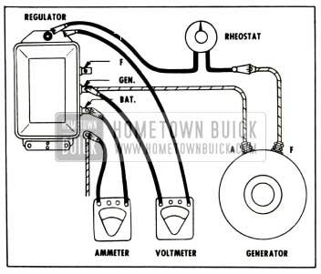
1958 Buick Testing Cutout Relay
- Disconnect field lead from regulator “F” terminal and connect a field rheostat (25 ohm-25 watt) between this lead and ground. Turn variable resistance to open position.
- Start engine and set carburetor on high step of fast idle cam (approximately 1500 RPM). Slowly turn rheostat variable resistance while observing both voltmeter and am meter. Note highest voltmeter reading just before ammeter moves off zero. This is the closing voltage of the cutout relay which should be between 11.8 and 13.5 volts.
- If cutout relay operation is otherwise satisfactory, but closing voltage is not between 11.8 and 13.5, remove regulator cover and adjust relay armature spring tension to obtain closing voltage of 12.8. Adjusting screw has a left hand thread, therefore, turning screw clockwise increases spring tension and closing voltage. Turning screw counterclockwise de creases closing voltage. After adjustment, in stall cover and recheck closing voltage.
CAUTION: Never close relay contacts by hand with battery connected to regulator be cause this will cause a damaging high current arc across contacts.
- Voltage Regulator Test . Turn rheostat variable resistance to open position and change one rheostat lead from ground to “F” terminal of regulator. Connect a 1/4 ohm resistor (approximately 25 watts) into charging circuit at “Bat” terminal of regulator. See Figure 10-7.
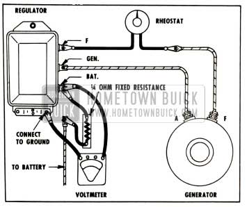
1958 Buick Testing Voltage Regulator
- Change red voltmeter lead from the “Gen” terminal to the “Bat” terminal. Turn rheostat knob to resistance out position. The voltage regulator is now controlling the charging circuit.
- When engine reaches normal operating temperature, set engine speed so that tachometer reads 1500 RPM either by adjusting fast idle screw, or by removing throttle rod return spring. ( 1500 RPM hot is correct fast idle adjustment.) Run engine at least 15 minutes total to permit regulator to reach operating temperature.
CAUTION: Since the voltage and current regulators are both compensated for temperature, the following tests must be made with the regulator at operating temperature with the cover in place to insure accurate results.
- Cycle the regulator by turning rheostat knob to open then back to resistance out. Now read voltmeter which indicates the maximum operating voltage (upper contact operation). This should be between 14 and 15 volts.
- If voltage regulator operation is other wise satisfactory, but maximum voltage is not between 14 and 15, remove regulator cover and adjust voltage regulator armature spring tension to obtain a maximum voltage of 14.5. See steps 19 and 20 below for adjusting procedure.
- Slowly turn the rheostat toward the open position while watching voltmeter. The volt meter reading should drop off between .1 and .3 volts at an even rate and then remain steady while rheostat is turned through a considerable angle. This steady reading is the operating voltage of the lower set of contacts which must be between . 1 and .3 volts below maximum voltage.
NOTE: The voltage “difference” between the operation of upper and lower contacts is increased by slightly increasing the air gap between the armature and the center of the core and decreased by slightly decreasing the air gap. See Step 20 below for procedure. If this adjustment is made, it will also affect the Maximum operating voltage (upper contact operation), so the maximum voltage must be rechecked.
- Current Regulator Test . Turn rheostat variable resistance to open position. Remove 14 ohm resistor. CAUTION: Do not allow disconnected lead to touch ground on car.
- Turn on all accessory load (lights, radio, blower, etc.) and connect an additional load from the charging circuit to ground and connect ammeter as described in your test instrument pamphlet. See Figure 10-8.
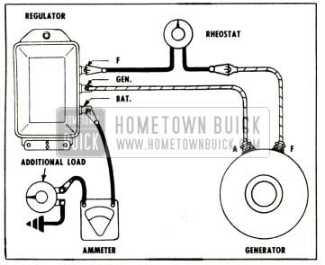
1958 Buick Testing Current Regulator
- Turn variable resistance to resistance out position. Read ammeter which now indicates the setting of the current regulator. (If a variable load is used, rotate load control knob for highest possible reading.) This should be between 42 and 48 amperes.
- If current regulator operation is otherwise satisfactory but maximum current setting is not within the above range, remove regulator cover and adjust current regulator armature spring tension to obtain a current setting of 45.
CAUTION: Never substitute an Air Conditioner regulator for a standard regulator as this might cause generator to burn out.
- If there is abnormal fluctuation of volt meter or ammeter pointer while testing voltage or current regulator, test for oxidized contact points.
- If contact points are in satisfactory condition but either the voltage or current regulator did not operate within specified limits adjust armature spring tension as required. Turn adjusting screw clockwise to increase operating voltage or charging rate. The final setting must always be made by turning screw clockwise to increase voltage or charging rate never by turning counter clockwise.
Adjust voltage regulator to obtain a maximum voltage of 14.5. Adjust current regulator to obtain a charging rate of 45 amperes.
If adjusting screw is turned clockwise beyond normal range required for adjustment, the spring support may be bent so that it fails to return when pressure is relieved. If this happens, turn the screw counterclockwise until sufficient clearance exists between screw head and spring support, then bend support upward carefully until contact is made with screw head. Make final adjustment as described above.
- If voltage “difference” between operation of upper and lower voltage regulator contacts was not within limits (.1 to . 3 volts), adjust air gap between armature and center of core as required. To increase voltage “difference,” increase air gap by loosening contact support bracket screw 1/8 to 1/4 turn. Then place a screwdriver through slot in bracket into molded insulator and raise on handle slightly. Retighten contact support bracket screw securely.
- After any adjustment of either regulator unit install cover and gasket, bring regulator up to operating temperature and recheck setting.
- Upon completion of all tests and adjustments, disconnect regulator test equipment and reconnect battery wire to “BAT” terminal of regulator. Before starting engine, momentarily bridge between the “BAT” and “GEN” terminals with a screwdriver to polarize the generator.
- Set engine idle speed at 485 RPM, then disconnect tachometer.
10-10 GENERATOR REGULATOR REPAIRS-ON BENCH
The contact points of a regulator will become oxidized and pitted after extended service and require cleaning. Contact points also may be burned because of faulty connections in the charging circuit, shorts or grounds in the generator field circuit, installation of a radio bypass condenser on the “F” terminal of generator or regulator, or accidentally grounding the generator or regulator field terminal while these units are connect d and operating together.
The majority of regulator troubles arise from dirty and oxidized contact points, which cause a reduced generator output. If contact points are not badly burned, cleaning followed by testing and adjusting will correct faulty regulator operation in most cases. However, if contact points are badly burned, it is generally better to replace the generator regulator.
The contact points are of a soft material and should be cleaned with crocus cloth or a similar fine abrasive material. After cleaning, thoroughly wash the contact points with trichloroethylene or alcohol to remove any foreign particles.
CAUTION: Never use emery cloth or sandpaper on the contact points because particles of emery or sand may become imbedded and cause the points to arc and burn.
After thoroughly cleaning and washing the contacts, make the generator regulator tests and adjust if necessary. If the regulator still does not operate in a satisfactory manner, replace the regulator.
SECTION 10-D LIGHTING SYSTEM
10-11 HEADLAMPS
More lighting and better control is achieved in 1958 by use of Buick’s Dual Headlamp sys tem. The Dual Headlamp system is standard equipment on all series and consists of two dual headlamps, one mounted on each side of the car.
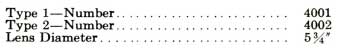
Each dual headlamp includes two 5 3/4″ T-3 sealed beam units mounted in a single housing enclosed by one headlamp door. The inboard unit is used for bright lights only and has a single filament. The outboard unit is used for both bright and dim lights and has two filaments. For identification, the inboard unit is marked “1,” the outboard unit is marked “2”. See Figure 10-9.
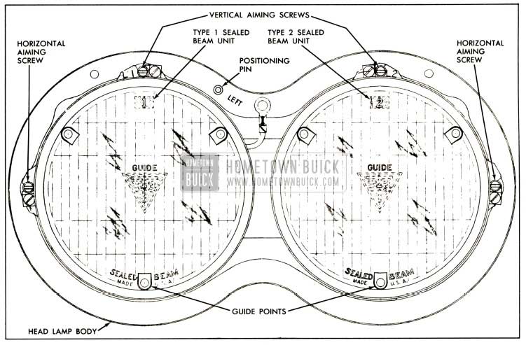
1958 Buick Left Dual Head Lamp Assembly
When the dimmer switch is in the dim or lower beam position only, the outboard (type “2”) unit of each dual head lamp is on. Both outboard (type “2”) and inboard (type “1”) units of each dual headlamp are on when the dimmer switch is in the bright or high beam position.
10-12 REPLACEMENT OF DUAL HEADLAMP ASSEMBLY
On the 1958 Buick Dual Headlamp assembly ill should be noted that two positioning pins are used, one in each headlamp body. On the right headlamp body the pin is located to the left of the centerline, and on the left headlamp body the pin is located to the right of the centerline. For identification, “right” or “left” is stamped on the headlamp bodies.
The right and left headlamp assemblies are not interchangeable, and when replacing either, it is important that they be correctly installed. If this procedure is not followed, the correct sealed beam unit cannot be located in its proper position. Also, due to the manner of positioning, only the headlamp assemblies designed for Buick should be installed as replacements.
10-13 NEW GUIDE T-3 HEADLAMP AIMER
The Guide T-3 Safety Aimer makes it possible to precision-aim Buick’s dual headlamp system in a minimum amount of time and space and to check the aim of the headlamps without removing the headlamp doors. The T-3 Aimer is the onl11 factory approved aimer for aiming Buick’s dual headlamp system, and meets the SAE specifications for mechanical aimers. This aimer can be converted to aim 7″ sealed beam units as previously used, by installing an adapter furnished with the aimer.
No screens or other aiming equipment are needed and aiming can be accomplished in daylight or darkness without the headlamps turned on. An average stall is all that is required since only sufficient room is needed for a man to walk around the car. A stall with a level floor is preferred so that aimer can be used just as received from the factory without being recalibrated.
The T-3 Aimer comes from the factory with level bubbles accurately set and instructions for rechecking the level accuracy after aimer has been in use. It is important that these instructions be followed when aimer is received and before it is used, as a precaution in case aimer is dropped or damaged. The aimer can be used in selecting an area for headlamp aiming and can be calibrated to compensate for uneven floors. The procedure for checking and adjusting headlamp aim is the same on coil spring and Air-Poise equipped cars.
Pictured below, Figure 10-10 is the Guide T-3 Safety Aimer for the left-hand dual head lamp.
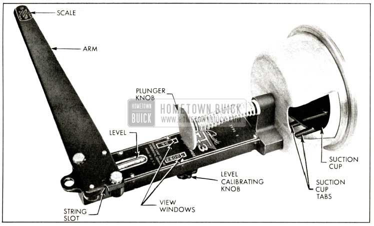
1958 Buick Left T-3 Aimer
10-14 CHECKING HEADLAMP AIM
NOTE: It is not necessary to remove headlamp doors to check headlamp aim.
Mounting Headlamp Aimer
- Drive the car onto the selected aiming area.
IMPORTANT: For an accurate headlamp aim the floor must be level or the T-3 Safety Aimer must be calibrated for the selected aiming area, in accordance with instructions received with aimer. Also, all future aimings must be made with cars placed on the same area faced in the same direction.
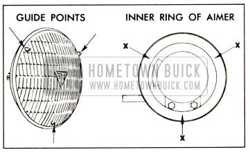
- Mount the T-3 Safety Aimers on each of the inboard units (type “1”) so that the lamp guide points engage smooth inner ring of aimer at points “X” and the arm on each aimer points toward center of car. See Figure 10-11.
1958 Buick Positioning Headlamp Aimer
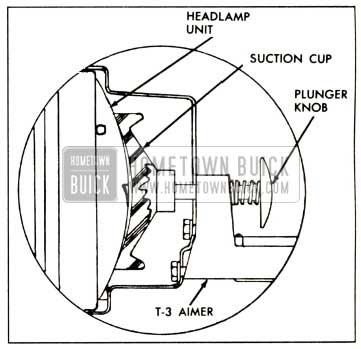
- Secure Safety Aimer to each headlamp unit by pressing plunger knob firmly. Rotate arm to approximately horizontal position. See Figure 10-12
1958 Buick Attaching Aimer
- With aimers in place, position the knots on each end of the elastic string in the slots provided on both aimers. Car doors must be closed and car rocked gently sideways to equalize springs, prior to checking and adjusting headlamps. See Figure 10-13.
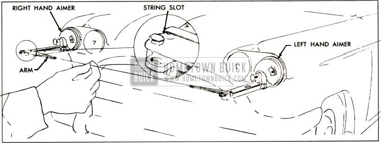
1958 Buick Positioning String
- Rotate aimers around headlamp units so that the scale on each aimer just clears the string.
- For aiming both inboard (type “1”) and outboard (type “2”) units, loosen level calibrating knob and slide knob rearward or for ward until numeral “2” appears in DOWN view window. Tighten knob of the aimer. All future checking and adjusting of headlamp aim will be done with aimer calibrated with numeral “2” in DOWN view window.
Checking Horizontal Aim
- The string should cross between right and left line “2” on scale of aimer. If the string does not fall within these limits it is necessary to adjust horizontal aim using procedure in Par. 10-15.
- Check horizontal aim of other type “1” unit as instructed above.
Checking Vertical Aim
- The bubble should be within the two outside lines of the level on the aimer. If bubble in level does not fall within these limits it is necessary to adjust vertical aim using procedure in Par. 10-15.
- Check vertical aim of other type “1” unit as instructed above.
- Remove aimers by pulling on the suction cup tabs through opening in aimer. Mount the aimers on each of the outboard units (type “2”) and check headlamp aim of the type “2” units as instructed in above sub. pars. a, b and c.
10-15 ADJUSTING HEADLAMP AIM
Mounting Headlamp Aimer
- Remove the headlamp doors and replace any defective unit.
- Mount T-3 aimers on Type “1” units as instructed in Par. 10-14, sub. par. a, Steps 1 through 6.
Adjusting Horizontal Aim
- Turn horizontal aiming screw on left hand unit until the string is positioned directly over the center line of the scale on the left-hand aimer. Turn screw clockwise in making final adjustment to take up play in the head lamp mechanism. See Figure 10-14.
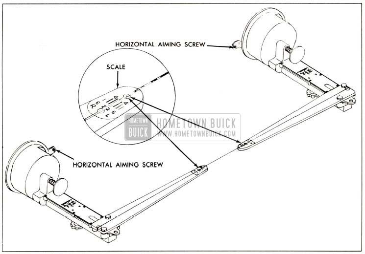
1958 Buick Adjusting Horizontal Aim
- Repeat the same operation on the right-hand unit to position the string directly over the center line of the scale on the right-hand aimer.
Adjusting Vertical Aim
- Turn headlamp vertical aiming screw counter-clockwise until the bubble in level is at the end of vial toward headlamp unit. Then turn screw clockwise until bubble is centered in the level. See Figure 10-15.
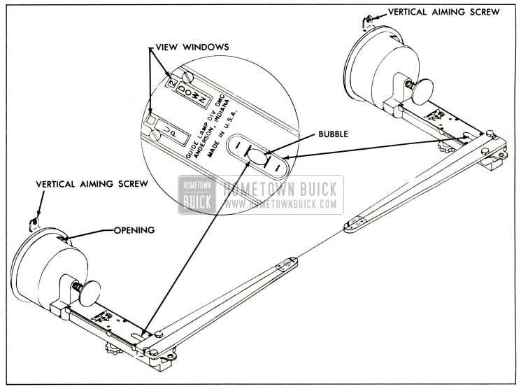
1958 Buick Adjusting Vertical Aim
- Repeat Step 1 on the other headlamp unit.
- Recheck the position of the string on the scale of the aimers, and the bubble in the levels.
- Remove aimers by pulling on the suction cup tabs through opening in aimer and mount aimers on the outboard units (type “2”) and adjust as instructed in above sub. pars. a, b and c to complete headlamp aiming procedure. Install headlamp doors.
10-16 FRONT PARKING AND DIRECTION SIGNAL LAMPS
The front direction signal and parking lamps are located in the outer grille extensions.
10-17 BACK-UP LAMPS
In 1958, the back-up lamps are housed in a recessed pocket located at the outer end of the rear bumper end plate assemblies on Series 50, 70 and 700. On Series 40 and 60, back-up lamps are located in the lower part of the combination stop, tail and direction signal housing.
NOTE: To replace a back-up lamp bulb on the Series 50, 70 and 700, the lamp assembly must be removed from the rear bumper end plate. From inside of rear bumper end plate, remove two back-up mounting nuts and drop lamp assembly down below end plat e so lens can be removed and new bulb installed. To replace a back-up lamp bulb on the 40-60 Series, remove rear lamp lens retaining screw ; lens and vertical bar are then removed as an assembly .
10-18 REAR LAMPS
Completely new concave tail, stop and direction signal lamps are used on all 1958 Series. A single lens on the 40, 60, 50 and 70 Series is divided by a vertical bar running upward from the reflex to a molding at the top of the lamp. The lens on the 700 Series is divided into five sections by four horizontal bars.
10-19 GUIDE AUTRONIC-EYE AUTOMATIC HEADLAMP CONTROL
General Description
The Autronic-Eye is an electronic device that automatically switches the headlamps between the upper and lower beams in response to light from approaching cars. The electrical power to operate the Autronic-Eye comes from the headlight terminal of the regular light switch and it is therefore energized whenever the light switch knob is pulled fully out. Over load protection is provided by the regular thermo circuit breaker on the light switch.
The Autronic-Eye consists of four separate units: a power relay, a combination dimmer override foot switch, an amplifier, and a photo tube. See Figure 10-16.
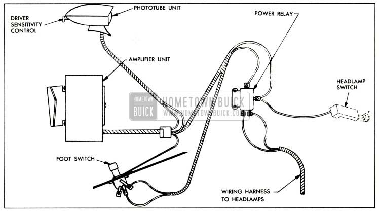
1958 Buick Autronic-Eye Components
The power relay, mounted in the engine compartment, is a heavy duty relay which switches the headlamps between the upper and lower beams. It switches the headlamps to the upper beam when the relay actuating circuit is grounded by the amplifier. When the amplifier interrupts the relay actuating circuit, a return spring in the relay switches the headlamps to lower beam.
The foot switch, mounted in the toe pan at the far left, has two ratchet positions plus a special override section. The two regular positions are automatic and lower beam. The head lamps are controlled by the Autronic-Eye in the automatic position only; in the lower beam position, the headlamps are mechanically locked on the lower beam.
The override section of the foot switch functions only when the switch is in the automatic position. A slight pressure on the top of the switch provides upper beam, regardless of the amount of light on the phototube. This arrangement permits signaling, if desired, and pro vides a simple test for the automatic position of the foot switch.
The amplifier, mounted on the forward side of the left front door hinge pillar behind the kick panel, supplies voltage to energize the phototube. It receives and amplifies any signal from the phototube. If this signal is weak, the amplifier grounds the power relay actuating circuit; if this signal is strong, the amplifier interrupts the relay actuating circuit.
The phototube, mounted on the top left side of the instrument panel, is energized by voltage supplied by the amplifier. It is an optical device which picks up light from ahead of the car and converts this light into an electrical signal which is supplied to the amplifier. The sensitivity of the phototube is adjusted to compensate for the different amount of light coming through a clear or a tinted windshield. A driver sensitivity control, located at the rear of the phototube, provides the driver with a limited sensitivity adjustment. See Figure 10-17.
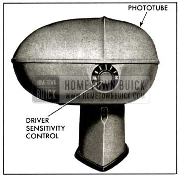
1958 Buick Autronic-Eye-Phototube
Operation
In the automatic position of the foot switch, the Autronic-Eye provides completely automatic switching of the headlamp beams. When a car approaches within proper distance, light from its headlamps striking the phototube causes the Autronic-Eye to switch the head lamps to the lower beam. At this time, if the approaching car’s headlamps were on upper beam, the driver would normally switch to lower beam which would greatly reduce the amount of light striking the phototube. The Autronic-Eye is designed to hold its vehicle headlamps on a lower beam even with this reduction in light. When light is removed from the phototube, the Autronic-Eye returns the headlamps to upper beam.
If the approaching vehicle fails to switch to lower beam, the override section of the foot switch may be operated to provide an upper beam for signaling purposes.
Street lights and other lights encountered in the city are sufficient to cause the Autronic Eye to hold its vehicle headlamps on lower beam.
The Autronic-Eye is disconnected from its vehicle headlamps in the lower beam position of the foot switch; however, the Autronic-Eye is not turned off. It continues to function as long as the headlamps are turned on, and is ready at all times to provide automatic control whenever the foot switch is returned to automatic position.
A driver control or sensitivity control knob is located at the rear of the phototube. This control gives the driver of the car a certain amount of control over sensitivity. A detent position (knob pointer straight up) is provided for normal sensitivity. Rotating the knob to ward “F” increases sensitivity, causing the headlamps to switch to the lower beam when an approaching car is farther away than nor mal. Rotating the knob toward “N” from the detent position decreases sensitivity, causing the headlamps to switch to the lower beam when an approaching car is nearer than normal.
Trouble-Shooting
The Autronic-Eye is adjusted at the factory and should hold its adjustment over a long period of time. Of course, there may be occasions when the adjustment is questioned. Like any other electrical device, a misunderstanding of the operation of the unit may lead one to believe that an adjustment is necessary. The following trouble may be reported:
- Normal Complaints
- Headlamps switch to the lower beam when an approaching car is too far away.
- Headlamps switch to the lower beam when an approaching car is too close or will not switch to the lower beam at all.
- Headlamps will not return to the upper beam when no car or other lights are ahead.
- Headlamps return to upper beam when the approaching car switches to lower beam.
- Headlamps switch rapidly back and forth between upper and lower beam.
- Checking Operation
While the above complaints may be corrected by simple aiming and sensitivity adjustments in most cases, a few operation checks should be made to determine if the difficulty is more serious than can be corrected by simple adjustment. With the car in a light area, check as described below:- Pull the light switch knob to full “On” position. After a few seconds warm-up time, the lights should remain on the lower beam, regardless of the position of the foot switch.
- Lightly depress the foot switch. The headlamps should switch to upper beam (as shown by upper beam indicator) if the foot switch is in the automatic position. If not, trip the foot switch and again depress to the over ride section. The lights should now switch to the upper beam. When the override section of the foot switch is released, the headlamps should return to the lower beam.
- Cover the phototube tightly with the palm of the hand. If the foot switch is in automatic position, the headlamps should switch to the upper beam. When hand is removed, the headlamps should switch back to the lower beam.
If the headlamps operate as explained in the above checks, the Autronic-Eye should operate correctly after making the adjustments as described in sub par. c below.
If trouble develops and immediate service is not available, standard foot switch operation of the headlamps can be obtained by removing the blue wire from its connector in the amplifier harness. IMPORTANT: The blue wire is “hot” so its terminal must be insulated with tape.
Adjustments
There are four adjustments which must be correct for proper operation of the Autronic Eye: phototube horizontal aim, vertical aim, amplifier hold sensitivity and dim sensitivity. Since any one of these adjustments could be a contributing factor to a complaint, all the adjustments should be checked in the order named and, if out of limits, corrected.
CAUTION: The Autronic-Eye develops a high voltage. Always turn headlamps off before removing cover from phototube.
- Installing Test Lamp and Aiming Device. The test lamp is a very accurate source of light which is connected to a test instrument. The test instrument has a rheostat to adjust the test light intensity and a meter to accurately read that light intensity. To install the test lamp, remove the phototube cover and insert from the front. An adaptor ring fits into the lens slot with a locator notch down to accurately locate the test lamp. See Figure 10-18.
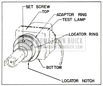
1958 Buick Autronic-Eye Test Lamp
The aiming device consists of a special photo tube cover with an adjustable lever and two sights. The level is set with a dial to compensate for the varying calibration in optics of each phototube. It is used to aim the phototube vertically. The two sights are used to aim the phototube horizontally. To install the aiming device, set it on the phototube base in place of the regular cover. Replace screws and tighten securely. See Figure 10-19.
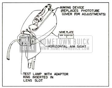
1958 Buick Aiming Device and Test Lamp Installed
NOTE: The aiming device contains a special plastic filter. This filter should be kept free of dust. If the filter is damaged, the aiming device must be returned to the tester manufacturer for repair. This filter does not replace the amber filter in the phototube which must be left in place.
- Horizontal Aim. The centerline of the phototube must be aimed parallel to the horizontal centerline of the car. Unsatisfactory operation on curved highways will result if horizontal aim is incorrect. The horizontal aim should be checked as follows:
- Locate car approximately 25 feet from a vertical wall or screen. See Figure 10-20.
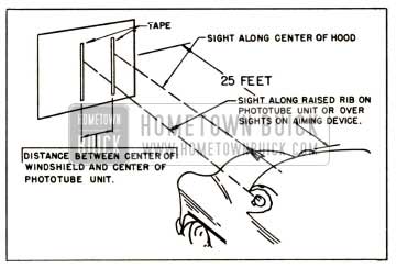
1958 Buick Horizontal Aiming
- Sight along the car hood and place a piece of tape vertically on the wall at hood height to represent the car centerline.
- Measure distance in car between car centerline and phototube centerline. Place a second piece of tape vertically on the wall this distance to left of first tape.
- Sights on aiming device should line up with the left tape within 4 inches to the right or left.
- If horizontal aim is incorrect, loosen small Allen screw in right side of phototube bracket using Allen wrench located inside tester cover. Rotate phototube until aim is correct. Tighten Allen screw and recheck horizontal aim.
- Vertical Aim. The phototube must be accurately aimed vertically. If the phototube is aimed too low, back reflections from the car’s own headlamps will cause it to hold the head lamps on the lower beam. On the other hand, if the phototube is aimed too high, it may not respond to the headlamps of approaching cars and may hold the headlamps on the upper beam when the car is heavily loaded.
- Phototube vertical aiming should be done with car at road trim height; that is, car unloaded except for person in driver’s seat, trunk empty except for spare tire, gas tank at least half full, and with tires at correct pressure.
- Locate car on a level floor (level within 1/4″ fore and aft of car).
- Observe number stamped on name plate on bottom side of the phototube. See Figure 10-21.
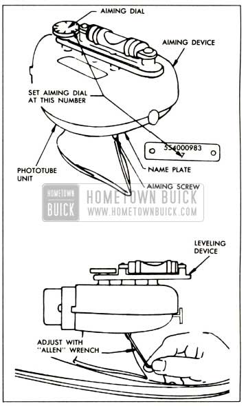
1958 Buick Vertical Aiming
Adjust aimer level dial until corresponding number is under pointer.
- Use Allen wrench located inside tester cover and adjust vertical aiming screw located in rear edge of phototube bracket until bubble is centered in the level.
- Hold Sensitivity. This is a test to see how low the light intensity at the phototube will go before the headlamps fail to “hold” on the lower beam and switch to the upper beam.
- Make sure test lamp is properly installed (step 1 above) and that tester intensity rheostat is turned full counterclockwise.
- Place driver sensitivity adjustment on phototube in detent position (knob pointer straight up).
- Start engine and set carburetor on high step of fast idle cam. This is necessary so that normal operating voltage will be present in the Autronic-Eye for all sensitivity tests and adjustments.
- Turn headlamps on and wait at least 5 minutes for amplifier to stabilize. Set foot switch in automatic position (upper beam indicator on).
- Turn zero corrector on face of meter until meter pointer is on zero set line.
- Insert tester connector into cigar lighter receptacle (Sun Tester only).
- Turn “DIM-HOLD” switch on “DIM” position. NOTE: Sun Tester provides different selector switch positions for clear of tinted windshields; Kent-Moore T ester provides different meter scales for clear of tinted windshields. See Figure 10-22.
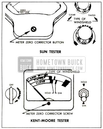
1958 Buick Autronic-Eye Testers
- Turn intensity rheostat full clockwise to obtain lower beam. If lower beam cannot be obtained, the amplifier dim adjuster must be turned completely clockwise and then readjusted later under “Dim Sensitivity” below.
- Turn “DIM-HOLD” switch to “HOLD” position.
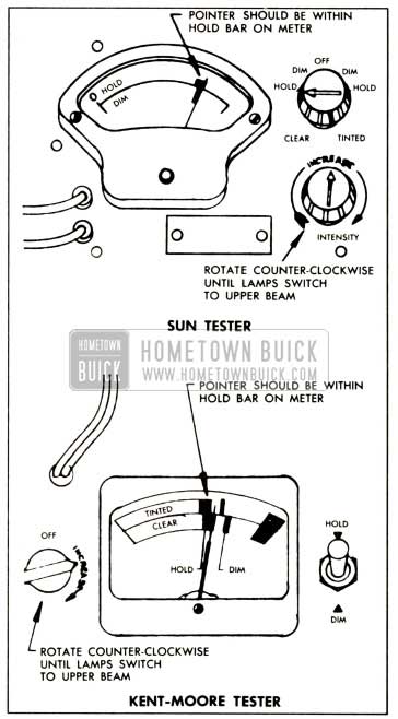
- Slowly turn intensity rheostat counter clockwise just to the point where headlamps switch to upper beam. The meter pointer should now read in the “HOLD” bar. See Figure 10-23.
1958 Buick Testing Hold Sensitivity
If it does, go on to the dim sensitivity test; if not, adjust the hold sensitivity as de scribed in the following steps.
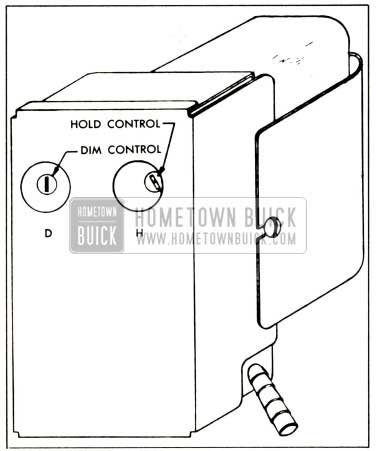
- Remove left kick panel and locate amplifier which is mounted on forward side of left front door hinge pillar. The hold control is available through a hole marked “H.” Using a small screwdriver, rotate the hold control completely clockwise.
- Rotate tester intensity rheostat all the way clockwise.
- Turn “DIM-HOLD” switch momentarily to “DIM” position to switch lights to lower beam; then switch back to “HOLD” position.
NOTE: If head lamps fail to go to lower beam, turn amplifier dim control clockwise.- Adjust tester intensity rheostat until meter pointer is at right-hand edge of “HOLD” bar. See Figure 10-24.
1958 Buick Adjusting Hold Sensitivity
- Turn amplifier hold control slowly counterclockwise just to the point where head lamps switch to upper beam.
- Rotate tester intensity rheostat all the way clockwise, turn “DIM-HOLD” switch momentarily to “DIM” position then back to “HOLD” position to obtain lower beam.
- Turn intensity rheostat slowly counter clockwise just to point where headlamps switch to upper beam. Meter pointer should now read in “HOLD” bar. If not, repeat procedure starting with step k.
- Dim Sensitivity. This is a test to see how high the light intensity at the phototube will go before the headlamps “dim” from the upper beam to the lower beam. NOTE: Dim sensitivity should not be adjusted until after hold sensitivity is properly adjusted.
- Rotate tester intensity rheostat completely counterclockwise.
- Turn “DIM-HOLD” switch to “HOLD” position and then back to “DIM” position. Headlamps should be on upper beam.
- Turn tester intensity rheostat clockwise slowly just to point where head lamps switch to lower beam. Meter pointer should read within the “DIM” adjustment line. See Figure 10-25. If not, proceed to step d.
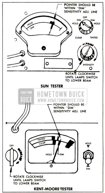
1958 Buick Testing Dim Sensitivity
- Rotate amplifier dim control completely counterclockwise.
- Momentarily turn tester off then back to “DIM” position.
- Adjust tester intensity rheostat until meter pointer reads in the right-hand edge of the “DIM” adjustment line.
- Slowly rotate amplifier dim control clockwise just to the point where headlamps switch to lower beam. Do not go beyond this setting.
- Turn tester intensity rheostat completely counterclockwise then momentarily turn tester off and then back to “DIM” position.
- Rotate tester intensity rheostat slowly clockwise just to the point where headlamps switch to lower beam. Meter pointer should read within the “DIM” adjustment line. If not, repeat steps d through i.
- If adjustment is correct, turn off headlamps and disconnect tester from cigar lighter receptacle (Sun Tester only) or turn Kent Moore tester off to keep batteries from discharging.
- Remove test lamp and a1mmg device from the phototube. Replace lens, cover and screws.
SECTION 10-E INSTRUMENT PANEL
10-20 INSTRUMENT PANEL
The redesigned instrument panel for 1958 will incorporate an easily removed upper panel as in 1957. Rather than just the center section, however, the upper section, extending to the corners of the panel, will be detachable as one piece. On all 60, 50, 70 and 700 Series, and on 40 Series equipped with upper instrument panel cover, the upper roll of the panel will remain in place when the upper panel is removed. On 40 Series without upper panel cover, the entire upper panel is one piece. This arrangement allows for greater accessibility of under panel wiring, instruments, etc., as well as for a more pleasing appearance.
WIRING DIAGRAMS
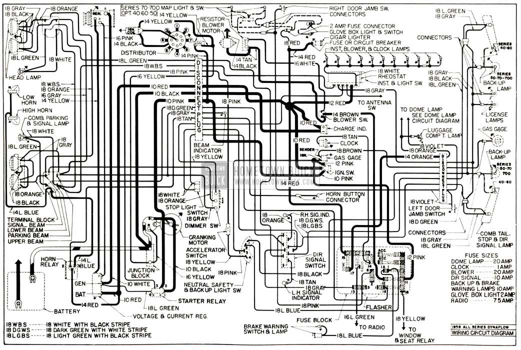
1958 Buick Chassis Wiring Diagram – Dynaflow Transmission
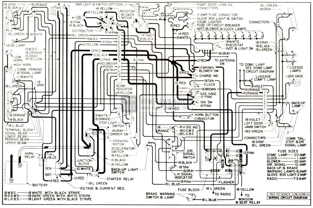
1958 Buick Chassis Wiring Diagram – Synchromesh Transmission
Leave A Comment
You must be logged in to post a comment.