SECTION 10-G 1957 BUICK LIGHTING SYSTEM
10-47 1957 BUICK LIGHTING SWITCH AND CIRCUIT BREAKER
Description of 1957 Buick Lighting Switch
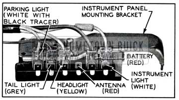
The switch has push-in-type wire terminals. Each terminal on the switch is color-coded to match the color of the wire. It is a “push-pull” type which also incorporates a manually operated rheostat for controlling the instrument panel lights. Three “push-pull” positions of the switch knob provide control of the 1957 Buick exterior lights as follows:
- “Off” position (knob all the way in) cuts off all 1957 Buick lights controlled by the switch.
- “Parking” position (knob pulled out to first notch) turns on the 1957 Buick parking lights, 1957 Buick tail lights, and 1957 Buick license light and key light. The instrument panel lights also will be turned on if the rheostat is set for these 1957 Buick lights.
- “Driving” position (knob pulled out to last notch) turns 1957 Buick parking lights off and turns 1957 Buick headlights on, while the other lights remain as in the “Parking” position. The headlights will be on the “upper” or “lower” beams depending on the position of the separate dimmer switch.
In the “Parking” and “Driving” positions, the 1957 Buick instrument panel lights are controlled by rotating the light switch knob. With the knob turned all the way counterclockwise, these lights are on maximum brightness. As the knob is turned clockwise, they gradually dim until they are off at the full clockwise position of the knob.
Description of 1957 Buick Thermo Circuit Breaker
A thermo circuit breaker is incorporated in the 1957 Buick lighting switch assembly, to protect wiring from damage due to short circuits in any lighting circuit controlled by the switch.
The thermo circuit breaker consists of a bimetal blade and set of contact points connected in series with the 1957 Buick lighting circuits. An abnormal flow of current through the circuit breaker, such as would be caused by a short circuit in a lighting circuit, heats the bi-metal blade sufficiently to separate the points and cause them to vibrate. The vibrating blade alternately opens and closes the circuit, thus reducing the flow of current and protecting the wiring against overheating and burning. The flickering light produced by the vibrating circuit breaker serves as a warning to the operator of vehicle that a short circuit exists.
Test of 1957 Buick Lighting Switch
If the 1957 Buick lighting switch is suspected of being faulty, the contacts can be tested by connecting a short jumper wire between the switch feed terminal and the other terminals while observing any change in the brilliance of 1957 Buick lights affected. See figure 10-52.
1957 Buick Lighting Switch
With switch in “Parking” position (first notch out) connect jumper wire between battery and parking light terminals and note change in parking lights. Bridge between battery and taillight terminals and note change in tail lights. With switch in “Driving” position (last notch out) bridge between battery and headlight terminals and note change in headlights.
If no change in brilliance of 1957 Buick lights is noted the switch contacts are satisfactory and the cause is in the wiring circuit connections or lamp bulb. If switch is faulty it must be replaced since internal repairs cannot be made.
Replacement of 1957 Buick Lighting Switch
- Disconnect battery cable from junction block and disconnect wires from 1957 Buick lighting switch.
- Pull switch knob out to last notch, then depress the spring loaded latch button on switch while pulling the knob and rod assembly out of switch.
- Remove switch mounting nut with Wrench J-1589-A and remove switch and escutcheon from instrument panel. See figure 10-52.
- When installing 1957 Buick lighting switch, connect wires according to color codes as shown on chassis wiring circuit diagrams in Section 10-J. When connecting battery ground cable use care to properly wind the clock (par. 10-56).
Test of 1957 Buick Thermo Circuit Breaker
To test the 1957 Buick thermo circuit breaker, remove 1957 Buick lighting switch from instrument panel to avoid possible damage to adjacent instruments.
Since the current required to open the circuit breaker contacts depends somewhat on outside temperature, the circuit breaker should be tested at normal temperature (70° to 80°F.).
- Connect an ammeter and a carbon-pile rheostat in series with the No. 1 terminal of lighting switch and positive terminal of a 12- volt battery, and set rheostat to provide maximum resistance. Rheostat must have capacity for 30 amperes and be adjustable down to .3 ohms.
- With switch on, connect the No.3 terminal of 1957 Buick lighting switch to negative post of battery.
- Adjust rheostat to give 30 amperes. The circuit breaker should start vibrating in four minutes or less.
- Adjust rheostat to give 22 amperes on ammeter. The circuit breaker should remain closed indefinitely at 22 amperes.
- If circuit breaker does not operate as specified the lighting switch assembly should be replaced. The circuit breaker is not adjustable and no attempt should be made to alter the calibration by bending the bi-metal blade. The contact points must not be filed or sanded.
10-48 1957 BUICK HEADLIGHTS AND CONTROLS
1957 Buick Headlamp Assembly
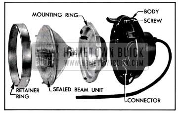
The 1957 Buick headlamp assembly on each front fender consists of a body, wiring, connector, mounting ring, sealed beam unit, retainer ring, door and gasket. See figure 10-54.
1957 Buick Headlamp Disassembled
The 1957 Buick headlamp body is attached to the fender with a gasket between body and fender to provide a water-tight seal. The wiring to which the connector is attached extends through rear of lamp body and connects to a terminal block on the radiator baffle. The mounting ring, which supports the sealed beam unit, forms a ball and socket joint with the body, to which it is attached by one coil spring and two beam adjusting screws. The sealed beam unit is plugged to the wiring connector and is held in the mounting ring by a retainer ring. The headlamp door, which covers the retainer ring, is attached by three captive screws.
1957 Buick Sealed Beam Unit and Headlight Beams
The 1957 Buick sealed beam unit consists of a lens, reflector, terminal plug, and two lamp filaments assembled into one securely sealed unit. The lamp filaments are located with respect to the reflector so that two separate and distinct headlight beams may be obtained, depending upon which filament is burning.
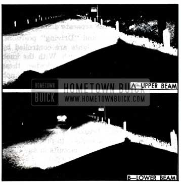
When the lower lamp filament is burning, an upper or straight forward light beam is obtained. The upper beam is designed to illuminate the road evenly, and is for use on the highway when no other vehicles are approaching. See figure 10-53, view A.
1957 Buick Light Distribution With Headlight Beams
When the upper lamp filament is burning, a lower or depressed light beam is obtained. The lower beam is designed so that it does not throw a dazzling light into the eyes of an approaching driver. At the same time, the distribution of light is such that the right side of road is illuminated as far ahead as is practicable without causing glare on curves. See figure 10-53, view B. The lower beam is intended for use in traffic and on the highway when meeting other vehicles.
Improved all-glass sealed beam units of the Guide T-3 type are specified for all models. These units provide increased visibility with either upper or lower beam, especially in bad weather.
This unit has a metal shield over the filament which helps block stray light. This new shield makes it possible to project more light farther down the road, but still reduces glare for an approaching vehicle.
The T-3 unit has three projections equally spaced around the perimeter of the lens. These projections are ground off at the factory to provide a mounting surface for the Guide T-3 Safety-Aimer. This aiming device is used without switching 1957 Buick headlights on as described below (par. 10-49, d).
1957 Buick Dimmer Switch
The driver may select the upper or lower headlight beam as traffic and road conditions demand by operating the dimmer switch mounted on the toe panel in a convenient position for the left foot.
The dimmer switch opens and closes the circuits to the upper and lower lamp filaments in both sealed beam units, thereby alternately raising and lowering the headlight beams with each successive operation of the switch. Depression of switch button turns the rotary contacts one position within the switch. The spring-loaded button automatically returns to the reset position when released. The switch contacts overlap so that the new circuit is closed before the previous one is opened, in order to prevent both beams being off at the same time during operation of the switch.
1957 Buick Headlight Beam Indicator
Whenever the upper 1957 Buick headlight beams are lighted, a beam indicator bulb on the instrument panel also lights, producing a small spot of red light in front of the driver. For safety reasons, he should never pass an approaching car with the beam indicator showing red.
10-49 1957 BUICK HEADLAMP SEALED BEAM UNIT REPLACEMENT AND ADJUSTMENT
Replacement of 1957 Buick Sealed Beam Unit
When a sealed beam unit is burned out or broken it must be replaced as a unit assembly.
- Remove headlamp door.
- Unhook the spring from retainer ring (fig. 10-55), then remove sealed beam unit and retainer ring, being careful not to disturb the two beam adjusting screws.
- Separate the sealed beam unit from the wiring connector.
- Spring the retainer ring slightly where marked “TOP” to remove mounting ring and sealed beam unit. See figure 10-54.
- Install new sealed beam unit by reversing removal procedure. The lens is marked “TOP” and the reflector has three lugs which fit into notches in the headlamp mounting ring. CAUTION: Make sure that sealed beam unit installed has “12V” molded in lens to indicate 12-volt unit.
- Before installation of headlamp door, adjust headlamp for proper aim as described below.
1957 Buick Headlamp Aiming Adjustment
The 1957 Buick headlamps must be properly aimed in order to obtain the maximum road illumination and safety that has been built into the head lighting equipment. With the Guide T-3 type sealed beam units, proper aiming is even more important because the increased range and power of this new lamp make even slight variations from recommended aiming hazardous to approaching motorists. The headlamps must be checked for proper aim whenever a sealed beam unit is replaced and after any adjustment or repairs of the front end sheet metal assembly.
Headlamp aiming machines are in general use. When using one of these machines make certain that it is in proper condition, and carefully follow the instructions of the manufacturer. Headlamp aiming charts are also available and will give good results if used properly; see subparagraph c below.
Regardless of method used for checking headlamp aim, car must be at curb weight, that is, with gas, oil, water, and spare tire, but no passengers. Tires must be uniformly inflated to specified pressure (par. 1-1). If car will regularly carry an unusual load in rear compartment, or a trailer, these loads should be on car when headlamps are checked. Some states have special requirements for headlamp aiming adjustment and these requirements should be known and observed.
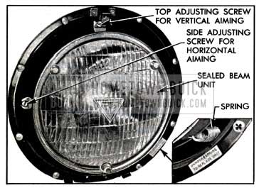
Horizontal and vertical aiming of the 1957 Buick headlamp beam is provided by the two beam adjusting screws which move the mounting ring in the body against the tension of the coil spring. There is no adjustment for focus since the sealed beam unit is set for proper focus during manufacturing assembly. If headlamps require adjustment for proper aim, proceed as follows:
- Remove headlamp door.
- Adjust light beam up or down as required by turning the top beam adjusting screw. See figure 10-55.
1957 Buick Sealed Beam Unit Mounting
Use of 1957 Buick Headlamp Aiming Chart
If a 1957 Buick headlamp aiming machine is not available a chart may be prepared as shown in figure 10-56.
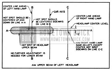
1957 Buick Headlamp Aiming Chart
It is desirable to make the chart on a large panel of plywood or other suitable material, painted flat white, so that it can be shifted into proper alignment with car, as explained later. Note that the chart consists of two horizontal and three vertical lines. The upper horizontal line is located at the same distance from floor as the center of headlamps and the lower horizontal line (A-A) is 2″ below the headlamp center line. Vertical lines B-B and C-C are located at the center of head lamps and equally distant from the center vertical line which corresponds to axis of car.
When using the headlamp aiming chart, place car on a level stretch with chart placed 25 feet ahead of both headlamp lenses, and parallel to them. Place a narrow piece of masking tape on the exact vertical centerline of the back window glass. Shift chart sideways as required to bring the center vertical line into exact alignment with the center of radiator ornament and center of the back window glass.
Set 1957 Buick lighting switch in “driving” position and operate dimmer switch to give upper beam. Cover right headlamp and note light pattern made on chart by the left headlamp. The center of zone of highest light intensity should fall on the intersection of horizontal line A-A and the vertical line B-B as shown in figure 10-56. Cover left headlamp and check right headlamp in the same manner.
Use of Guide Headlamp Aimer
The Guide T-3 Safety-Aimer makes it possible to precision-aim Guide T-3 headlamps in a minimum amount of time. No screens or other aiming equipment are needed and aiming can be accomplished in daylight or darkness without the 1957 Buick headlights turned on. Floor space requirements are cut considerably since only enough room is needed for a man to walk around the car. This aimer comes from the factory with the level bubbles accurately set. Pads on its base make it possible for it to be used as a level to check any given area.
Mounting Headlight Aimer
- Drive the car onto the selected a1mmg area. (Unlevel floors are covered in detail in the instruction book received with the aimer.)
- Remove the 1957 Buick headlight doors and install a set of Guide T-3 headlights if necessary. (NOTE Only Guide T-3 headlights can be used with the Safety-Aimer.)
- Mount the aimers on each headlamp so that points engage smooth inner ring of aimer. Be sure to mount left hand aimer (with string) first. See Figure 10-57.
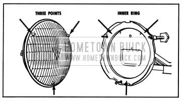
1957 Buick Mounting Aimer on Headlamp
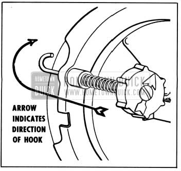
1957 Buick Fastening Aimer to Retainer Ring
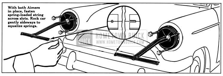
1957 Buick Fastening String Across Aimers
Horizontal Aim
- Adjust left headlamp by turning horizontal adjusting screw AA in or out to make string first touch point G. Final adjustment of screw should be made in a clockwise direction. See Figure 10-60.
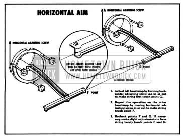
1957 Buick Headlamp Horizontal Aim
Vertical Aim
- Center bubble by turning vertical adjusting screw B. (To insure proper location, back screw out until bubble is at end of vial. Then turn screw clockwise to center bubble.) See Figure 10-61.
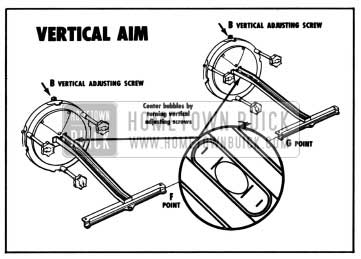
1957 Buick Headlamp Vertical Aim
10-50 1957 BUICK PARKING, TAIL, STOP, LICENSE AND BACK-UP LIGHTS
NOTE: See paragraph 10-5 for lamp bulb and fuse specifications.
1957 Buick Front Parking and Signal Lights
Each front parking and signal lamp contains one 32-4 CP lamp bulb which provides a 4 CP parking light and a separate 32 CP direction signal light. The pins on lamp bulb and slots in socket are offset to prevent improper installation of bulb in socket. The 1957 Buick parking light is controlled by the lighting switch and the circuit is protected by the switch thermo circuit breaker. The 1957 Buick direction signal light is separately controlled by the signal switch and the circuit is protected by the “DIR. SIGNAL” fuse on the fuse block under the cowl.
1957 Buick Tail and Stop Lights
The center section of each rear lamp assembly contains a 32 CP bulb which is used as a combination stop and direction signal light. Each upper section contains a separate 3 CP bulb for the tail light. The tail lights are controlled by the 1957 Buick lighting switch and the circuit is protected by the switch thermo circuit breaker.
The 1957 Buick stop lights are controlled by a hydraulic switch mounted in the master cylinder. The switch is closed by hydraulic pressure when the brakes are applied. The stop light circuit is protected by the 10 ampere “DIR. SIGNAL” fuse mounted on the fuse block under the cowl.
A lamp bulb may be replaced by removing the bezel from the rear lamp housing which is held in place by three screws.
Replacement of 1957 Buick Stop Light Switch
When replacing 1957 Buick stop light switch have new switch ready to install as soon as old switch is removed from master cylinder to keep brake fluid loss to a minimum. Always fill master cylinder reservoir after new switch is installed.
1957 Buick Rear License Light
A rear license lamp is mounted on each side of the license plate in the under surface of the rear bumper rail to provide adequate lighting of rear license plate. Each lamp contains one 3 CP lamp bulb which operates in conjunction with the 1957 Buick tail lights, and the circuit is protected by the lighting switch circuit breaker. Each lamp socket is mounted in rubber to protect the lamp filament from shock and a bronze grounding washer completes the circuit when the mounting bolts are tightened.
The lamp bulb may be replaced by removing the lens from the license lamp housing.
1957 Buick Back-up Lamps and Switch
1957 Buick back-up lamps are standard equipment on Series 70 car and are optional on all other series. They are located in the lower section of each rear lamp assembly and contain 32 CP bulbs behind clear plastic lenses.
On Synchromesh cars, the 1957 Buick back-up light switch is mounted on the steering column jacket. This switch is actuated by a pin on the switch itself which projects through a slot into the jacket. A short arm on the transmission control shaft actuates this switch pin while in the reverse position only. Slotted mounting screw holes permit movement of the switch up and down the steering column jacket for proper locating. See paragraph 10-31 (b) for adjusting procedure.
On Dynaflow cars, the 1957 Buick back-up light switch is combined with the neutral safety switch. It is mounted on the steering column jacket under the instrument panel. The switch is actuated by a lever on the transmission control shaft which projects through a slot in the jacket. When the neutral safety portion of the switch is correctly timed, the back-up portion is properly timed automatically. Slotted mounting screw holes permit sidewise movement of the switch for proper timing. See paragraph 10-31 (a) for the adjusting procedure for the neutral safety and back-up light switch.
10-51 1957 BUICK INTERIOR LIGHTS AND CIGAR LIGHTERS
NOTE: See paragraph 10-5 for lamp bulb and fuse specifications.
1957 Buick Instrument Panel Lights and Switches
The 1957 Buick speedometer, gauges, light switch, heater defroster or air conditioner control, and clock are illuminated by lamp bulbs mounted on forward side of instrument panel to provide indirect lighting. Illumination is also provided for the ignition lock and cigar lighter by means of a separate bulb and lens assembly which is held in place by spring clips. This bulb can be easily replaced by prying the bulb and lens assembly from the instrument panel.
The 1957 Buick instrument panel lights are controlled by the lighting switch as described in paragraph 10-47 and the circuits are protected by the switch thermo circuit breaker.
1957 Buick Instrument Panel Compartment Light
The 1957 Buick instrument panel compartment (glove box) is lighted by a lamp bulb mounted in a socket in the upper right corner of the glove box. The switch is mounted separately in the top right corner of the door opening. This spring-loaded switch makes contact when the compartment door is opened. As the door is closed it depresses the switch button to break contact and turn the light off. This circuit is protected by a 2 ampere fuse in the wiring connector behind the glove box.
1957 Buick Parking Brake Release Warning Signal
The 1957 Buick parking brake release warning signal, when installed, will show a red warning signal light on the instrument panel whenever the ignition switch is turned on while the parking brake is applied. The signal lamp is controlled by a switch mounted in position to be operated by the parking brake lever. The circuit is protected by a 10 ampere “BRAKE & BACK-UP” fuse on the fuse block under cowl.
When brake lever is in fully released position, the signal switch plunger must be depressed 3/16″. Adjustment is made by loosening the mounting screws and shifting the switch as permitted by the slotted screw holes.
1957 Buick Direction Signal Indicator Lights
The 1957 Buick direction signal indicator consists of a 2 CP bulb mounted at each end of the instrument cluster. A bulb may be replaced simply by pulling the socket from the back side of the cluster.
Bulb location is the same in all series cars. See paragraph 10-54 for a complete description.
1957 Buick Dynaflow Control Dial Light
The Dynaflow control dial on all Dynaflow cars is illuminated by a lamp bulb mounted on the forward side of the instrument panel to provide indirect lighting. The light is controlled by the 1957 Buick lighting switch in the same manner as all instrument panel lights. To replace the lamp bulb, remove the snap-in socket which is located directly under the instrument cluster.
1957 Buick Cigar Lighter
The Casco cigar lighter is heated by pressing the knob in until it latches; the knob will automatically unlatch and return to “off” position when heated to proper temperature. A replaceable thermal fuse located in the lighter base protects the lighter element against overheating if knob is manually held in for too long a period.
The lighter is equipped with an ash guard, to prevent ashes and loose tobacco from falling on the users clothing and to permit the lighter to be passed around without danger of burning the fingers.
Leave A Comment
You must be logged in to post a comment.