SECTION 11-B 1957 BUICK HEATER, AIR CONDITIONER
11-6 1957 BUICK HEATER AND DEFROSTER
1957 Buick Heater Installation Description
The combination heater and defroster core and housing is mounted low on the right side of the cowl between the cowl side panel and the right front fender. This high capacity core serves both the 1957 Buick heater and defroster systems which differ only in distribution of the heated air. The hot water is supplied to this core through the temperature control valve from the thermostat housing in the engine water manifold. It enters the bottom of the 1957 Buick heater defroster core and leaves at the top where it is conducted through a hose directly back to enter the radiator at the right side of the lower tank.
The blower located on the engine side of the right ventilator air duct cover, draws outside air through the cowl air intake screen and into the right air duct. The air is then forced from the blower into an air tube which delivers it to the 1957 Buick heater-defroster core. The air flows through the heater-defroster core into the inner heater and defroster core housing where it may be directed into either the 1957 Buick heater or defroster distribution system by means of two fly valves. For heating, the air is directed through the heater air distribution system to three heater outlets. One is located at each end of the instrument panel and the third outlet is located below and behind the center of the instrument panel. See figure 11-12.
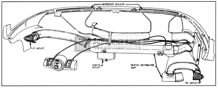
1957 Buick Heater and Defroster Outlets
The 1957 Buick heater-defroster system uses only outside air. However, when an air conditioner is installed, some interior air is recirculated.
Defroster and Outside Air Ventilation
For defrosting, the air is directed from the inner 1957 Buick heater-defroster core housing through a defroster air hose to two wide defroster outlets at the windshield. All the air may be directed through either the heating or the defrosting distribution system, or the air may be partially directed through both depending on the position of the two valves. See figure 11-24.
Two ventilation air vents are located on the lower dash panel, one on each side of the front compartment. The valves incorporated in these vents are controlled by two push-pull control knobs located on each side of the steering column on the lower instrument panel.
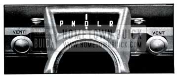
1957 Buick Outside Air Vent Controls
Water Flow and Temperature Control Valve
The hot water flows from the engine water manifold through a hose into the top of the Ranco valve. From the Ranco valve, the water flows through a hose to the bottom of the 1957 Buick heater-defroster core, out at the top, through a hose directly to the bottom of the radiator.
The system is equipped with 3/4″ I.D. hoses and 3/4″ Ranco valve.
A “jiggle pin” in the bleed hole of the engine thermostat allows air to escape through the bleed hole when filling the system, but seats, closing off the bleed hole when the water pump creates a small amount of pressure. The “jiggle pin” prevents water from circulating through the bleed hole and thereby facilitates quicker warm-up when engine is cold. The quicker warm-up supplys hot water more rapidly to the 1957 Buick heater-defroster core.
1957 Buick Heater, 1957 Buick Defroster and Ventilation Controls
1957 Buick Heater and Defroster Controls
Figure 11-14 shows the control panel which is used with the 1957 Buick heater and defroster installation. Figure 11-32 shows the control panel used with the air conditioner installation. Although the controls are positioned slightly different when an air conditioner is installed, the controls operate in the same manner as they do when only 1957 Buick the heater and defroster are installed.
The 1957 Buick heater and defroster air control is of the airplane type and the control lever is attached to fly valves in the inner heater and defroster core housing by means of a control wire. When the knob is pulled half-way down the defroster valve opens and allows air to flow into the defroster distribution air hose. Figure 11-22 shows the location of the heater and defroster control on an air conditioner equipped car.
When the 1957 Buick heater and defroster air control, as shown in figure 11-14, is moved to the bottom position it opens the heater valve in the inner heater and defroster core housing and allows air to flow into the heater air distribution system. At the same time the 1957 Buick defroster air valve is closed.
The blower speed is controlled by a rotary switch located in the center of the control panel. See figures 11-14 and 11-22. The switch has 3 positions, “Hi,” “Off,” and “Lo.”
The 1957 Buick heater temperature control lever, as shown in figure 11-14 and 11-22 regulates the temperature of the heater air entering the passenger compartment and is connected to the Ranco valve by a control wire. As the temperature control lever is moved from top to bottom the heater temperature is increased.
Inner 1957 Buick Heater and Defroster Core Housing
The 1957 Buick heater and defroster valves located in the inner heater and defroster core housing are operated by a cam type linkage which is designed to prevent valve flutter noise. See figure 11-24.
NOTE: To keep out offensive traffic odors and exhaust gases when traveling in congested traffic or when parked behind a car having its engine running, all ventilator and defroster valves must be closed and the blower must be turned off.
WARNING-CARBON MONOXIDE
Avoid inhaling exhaust gases when any concentration of these is present in the air, i.e., in a garage, in congested traffic, or when stopped closely behind a vehicle with its motor running. Exhaust gases may have strong odors which normally should give warning of their presence. However, the exhaust gases from some vehicles may not be noticeable under certain conditions and the senses of people react differently. Exhaust gases contain a percentage of carbon monoxide, which is a poisonous gas that, by itself, is tasteless, colorless, and odorless.
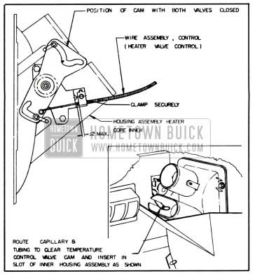
1957 Buick Temperature Control Valve Wire Adjustment
The 1957 Buick temperature control valve is operated by a lever through a sheathed operating wire. To insure full range of temperature control, the valve must act as the stop at both ends of lever travel. Since the operating wire is of fixed length with loops at each end, full range of operation is obtained by clamping the operating wire sheath in proper location on the control lever support and the temperature control assembly as follows:
- Connect operating wire to control lever and clamp end of sheath approximately 1/8″ from edge of clamp on lever support. Move lever to within 1/16″ of extreme “OFF” position.
- Turn temperature control valve all the way clockwise until the cam locks against the roller. This is the extreme “off” position. Connect operating wire to brass post on valve and clamp the sheath to valve assembly.
- Operate the control lever through full range to make certain that the valve provides the stop at both ends.
11-7 1957 BUICK AIR CONDITIONER
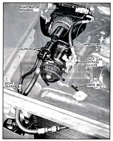
The 1957 Buick Air Conditioner is dash-mounted with all the components located in or ahead of the dash. The compressor and condenser are located as shown in figure 11-15.
1957 Buick Air Conditioner Installation
The receiver-dehydrator tank is vertically mounted along the right side of the condenser. The evaporator with its case and blower are mounted forward of the dash panel on the right side. All units are joined with high pressure hoses provided with double flare fittings. Units provided for field installation come already connected together and charged with 5 pounds of Freon 12, and are installed as a unit without breaking any of the connections. The air conditioner uses the same air distribution system as the 1957 Buick heater with an additional outlet in the center of the upper instrument panel.
Locations of the various units of the 1957 Buick Air Conditioner system and their connecting hoses are shown in figure 11-15. Figure 11-36 shows the electrical control circuit, which is entirely separate from all other chassis and body wiring.
Any service work that requires breaking a pipe joint or hose connection should be performed only by mechanics who have been trained in Buick or other automotive air conditioning schools. Whenever a hose is disconnected from any unit refrigerant will escape unless the proper procedure is used. Any work involving the handling of refrigerants requires special equipment and a knowledge of its proper use.
Description of Components
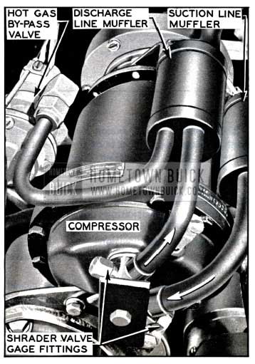
- Compressor and Clutch. The axial piston type compressor is mounted on the right-front of the engine, over the generator. The compressor to engine speed ratio is approximately 1.25 to 1.
The 1957 Buick mufflers are located in each compressor attaching line, one in the suction line and one in the discharge line. They consist of cylinders approximately 2%” in diameter by 3″ long containing interior baffles that greatly reduce the characteristic pumping sounds of this compressor.
The main shaft seal seat is located ahead of the seal body. The clutch hub is retained to the main shaft by a woodruff key and a press fit. The pulley bearing is also a press fit to the shaft and is retained in the pulley by a snap ring. See figure 11-16.
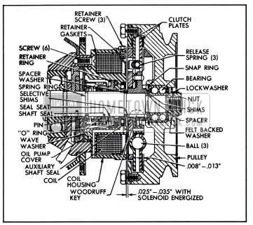
1957 Buick Compressor Clutch and Pulley
The compressor clutch is actuated by an electro-magnetic coil housed between the clutch and pulley assembly and the compressor housing. Two dry disk clutch plates, separated by three nylon balls, are used. Each plate has a flat ring of frictional material bonded to its contact face. The forward clutch plate is fixed to the compressor main shaft by a woodruff key and press fit. The clutch plates are connected to each other only through three small coil springs, positioned to oppose the torsion of the driving force.
When the coil is energized a magnetic field is created which attracts the rear clutch plate and pulls it into contact with the clutch cover ring. The frictional forces overcome the three torsion springs (See figure 11-17) and cause enough relative rotation between the clutch plates to make the nylon balls roll up their ramps, spreading the clutch plates apart and forcing them into firm contact with their mating surfaces.
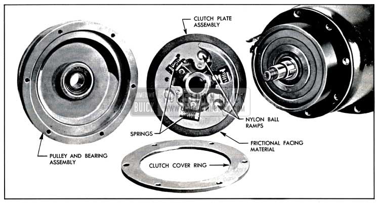
1957 Buick Compressor Clutch and Disc Assembly
This provides a solid connection between the pulley and the compressor main shaft.
When the clutch coil is de-energized, the magnetic field collapses and the rear clutch plate is no longer held against the clutch cover ring. The three coil springs overcome the servo-action of the nylon balls and force the clutch plates into a neutral position, disengaging the pulley from the main shaft.
- The connecting elements are made from a high temperature, high pressure synthetic rubber hose with double cord reinforcements. The hose ends are fitted with double flare fittings. The hoses are of sufficient length to be adaptable to all models in all series.
- Condenser and Receiver-Dehydrator. The condenser is mounted ahead of the radiator. The receiver-dehydrator tank is attached directly to the right side of the condenser frame along with a horn mounting pad. A sight glass is located in the liquid line from the receiver dehydrator, immediately behind the right radiator side baffle.
- Thermostatic Expansion Valve. A nonadjustable expansion valve is located at the bottom of the evaporator core on the outside of the case. The liquid enters the valve at the 3/8″ flare fitting, passes through the needle seat orifice, and leaves the valve at the 1/2″ flare connection and enters the evaporator. See figure 11-18.
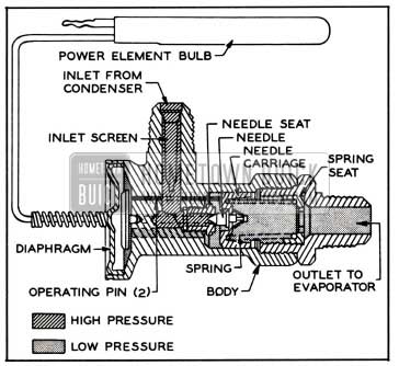
1957 Buick Non-adjustable Expansion Valve
The power element or bellows cap of the valve is connected by a capillary line to a thermo bulb which is clamped on the low pressure line between the evaporator coil and the low pressure line muffler.
- Evaporator and Blower. The evaporator core measures approximately 10″x10″x3″ thick and consists of an aluminum brazed plate type coil. This coil is housed in a plastic impregnated fibre glass (Formadall) case which is mounted to the dash panel on the right side in the engine compartment, replacing the right hand ventilation air duct cover.
The blower assembly mounts directly to the evaporator housing, on the front side, and is connected to the outer heater core housing by a large Formadall air duct.
- Hot Gas By-pass Valve. Figure 11-19 is a schematic view of the operating refrigeration cycle using the hot gas by-pass valve and showing this valve’s relative position in the system.
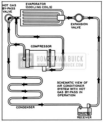
1957 Buick Air Conditioning System-Schematic
The manually controlled hot gas by-pass valve is connected to the evaporator to compressor suction line near the evaporator outlet. It is also connected to the compressor high pressure (discharge) line between the compressor and the condenser. The temperature of air coming out of the evaporator may be controlled between approximately 43° and 60° by varying the air conditioner temperature control lever which is connected to this valve.
The valve accomplishes this temperature control by metering hot high pressure Freon from the compressor discharge line into the low pressure (suction) line near the evaporator outlet. By this metering the valve maintains any pre-determined minimum evaporator outlet (Freon) pressure between approximately 29 and 55 psi. The pressure regulation in turn affects the thermostatic expansion valve which varies the metering of liquid Freon into the evaporator coil. As the cooling of the air passing through the evaporator coil depends directly upon the quantity of liquid Freon that is allowed to expand (evaporate) in the coil, the conditioned air temperature is effectively controlled.
The operating pressure of the hot gas bypass valve is set by means of the adjusting screw which compresses the pilot valve spring. See figure 11-20.
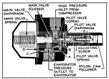
1957 Buick Hot Gas By-pass Valve-Sectional
This spring pressure is opposed by the evaporator pressure acting on the pilot valve diaphragm through passage “A”. Using 29 psi as the desired evaporator pressure which will prevent freezing, the following takes place as long as conditions are such that the evaporator pressure is more than 29 psi, the pressure in Area “B” opposes the pilot valve spring and the unit is sealed and has no effect on the system. When the evaporator pressure drops to the 29 psi setting, the pilot valve spring opens the pilot valve allowing gas at head pressure to pass through passage “C” and apply against .the main valve diaphragm in Area “D” which compresses the main valve spring and moves the main valve from its seat permitting gas to pass through to the suction line. These valves position so as to permit enough flow of hot gas to maintain the 29 psi setting. This setting has been referred to as “freeze protection.” If a higher temperature is desired, or less cooling, the pilot valve spring is compressed further than “freeze protection” by means of a Bowden wire and lever acting on pin “E”. Then the same “metering” cycle takes place but at a higher pressure and, consequently, higher temperature.
- Air Distribution System. The air conditioner air distribution system makes use of the heater air ducts with special outlets at the outer ends of the instrument panel plus an additional outlet located at the top center of the instrument panel.
The outlets on either end of instrument panel are adjustable. They may be adjusted to direct air up, down, inward toward the center of the car, or outward toward the door panels. Heated or air conditioned air is circulated to the rear seat area when the instrument panel outlets are adjusted so that air is directed along the door panels. See figure 11-21.
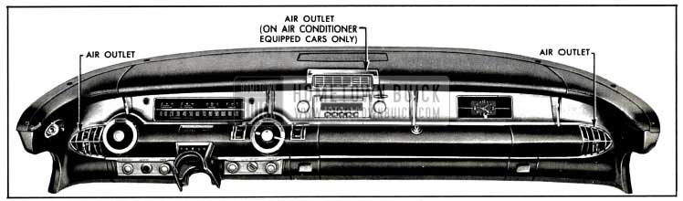
1957 Buick Air Distribution System Dash View
As both the air conditioning and 1957 Buick heater defroster systems are dash-mounted it is possible (on cars so equipped) to operate both systems simultaneously to effect dehumidification of the ventilation air when neither heating nor cooling are required. When the air conditioning system is in use the right air vent (under the instrument panel) is converted to a return air duct to provide the evaporator blower with cooled air to recirculate. This results in lower car temperatures than are possible with systems using 100% outside air.
Outside air is used exclusively for heating when an air conditioner is not installed. Recirculated air, along with outside air is used when an air conditioner is installed. A fixed orifice in the evaporator case proportions the outside air to total air that is to be air conditioned. The right outside air vent valve is automatically opened to allow recirculation when the air conditioning unit is operating.
A spring loaded pressure relief valve in the right outside air vent valve is necessary to prevent cold air from entering the car when the heater blower is off. This valve is used only when air conditioning unit is installed, permitting air to recirculate and enter the heating core when the 1957 Buick heater blower is on.
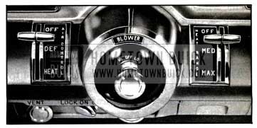
- The left lever (1) shown in figure 11-22 is the cold range control lever.
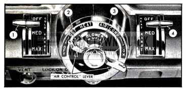
1957 Buick Air Conditioner Controls
Maximum cooling position is at the bottom and moving this lever through its full range from bottom to top controls the outlet air temperature from approximately 43° to 60°. “OFF” position on this lever does not turn the air conditioner off.
The center lever (2) controls the positioning of the air valves in the 1957 Buick heater defroster inner housing, the right fresh air vent and in the heater air distribution duct. It also controls the air conditioner clutch switch at the right end of its travel (“ON” position). When this lever is in the “OFF” position all valves except the distribution duct valve are closed. As the lever is rotated clockwise to “DEF” position the defroster valve opens; as lever is rotated further clockwise to “HEAT” position the defroster valve closes as the 1957 Buick heater valve opens. Rotating the valve to the extreme right (“ON” position) closes the distribution duct valve and opens the right vent valve-the heater valve remains open and the defroster valve remains closed. The air conditioner clutch coil is energized just before the lever reaches the full “ON” position.
The blower control knob (3) controls the blower switch. This is a 3 position (high-off-low) rotary switch that controls the blower speed.
The right lever (4) is the heater temperature control which is connected to the Ranco valve by a Bowden wire. Moving the lever from “OFF” position at the top to “MAX” at the bottom increases the 1957 Buick heater-defroster core temperature within the limits of engine heat. “OFF” position closes the Ranco valve mechanically and stops the flow of coolant through the 1957 Buick heater-defroster core.
Operation
To place the 1957 Buick air conditioner in operation (cooling):
- Make certain that the left fresh air vent is closed and that the heater temperature control (Ranco valve) lever is in the extreme upper (“OFF”) position.
- Rotate center lever full clockwise to “AIR COND-ON” position.
- Start engine and adjust cold range lever, blower speed switch and the three outlets as desired to control temperature _and air circulation.
For maximum 1957 Buick air conditioner performance all windows and ventilators must be closed.
If dehumidification is required without cooling move the right control lever down until the desired temperature is obtained. This must be done with the air conditioner in operation as described in steps 2 and 3 above. Dehumidification consists of cooling the incoming air (which removes most of the moisture) then re-heating to the desired comfort level.
Adjustments
- Hot gas by-pass Control Adjustment. To adjust the temperature control linkage, set the temperature control (left hand) lever on the lower roll of the control panel to “Max.”. Disconnect Bowden wire loop from pin on lever of hot gas by-pass valve. Push lever on bypass valve all the way toward the dash and release slowly. Lever will stop in “Max.” cooling position. Adjust Bowden wire sheave so loop matches position of pin on lever. Clamp Bowden sheave in position with loop encircling pin and replace spring grip washer.
In the event that it becomes necessary to adjust the hot gas by-pass valve adjusting screw (See fig. 11-20) to correct the suction (back) pressure, the following procedure should be used:
- Disconnect the valve control wire.
- Remove valve control lever, counterbalance spring and nylon cam follower.
- Connect service (high and low pressure) gauges to compressor.
- Set engine speed at 1600 RPM, turn unit on and allow time for stabilization.
- Turn adjusting screw in or out to obtain proper 28-30 lb. reading on the suction (back) pressure gauge.
- Remove gauges, replace protective caps, cam follower, control pin, lever and spring and then re-adjust and connect control wire as outlined above.
- Thermostatic Expansion Valve. The thermostatic expansion valve is of the pre-set nonadjustable type. If detailed diagnosis proves this valve bad, it must be replaced.
- Control Adjustments. The 1957 Buick Heater and Air Conditioner Air Control (2 in fig. 11-22) is adjusted by positioning the control lever to the full “OFF” (counterclockwise) position. With control in this position:
- Both heater and defroster air valves should be closed.
- Right fresh air vent should be closed.
- Center heater distribution duct valve should be open.
With control in “AIR CONDON” (full clockwise position:
- Defroster valve should be closed and heater valve wide open.
- Right fresh air vent valve should be open.
- Center heater distribution duct valve closed.
- Air conditioner clutch control switch should be closed. (Energizing clutch coil).
For adjustment of 1957 Buick heater temperature control wire refer to par. 11-6, subpar. f. See Figure 11-23 for details.
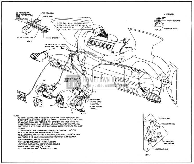
1957 Buick Air Conditioner Controls and Linkage
11-8 COMPRESSOR SERVICE PROCEDURES
NOTE: Before the engine is raised or lowered for any service operation the high and low pressure lines must be disconnected from compressor, as described in subparagraph a, steps 1 through 6.
1957 Buick Heater and Defroster Core Inner Housing
Removal and Installation of Compressor
CAUTION: Observe precautions in handling Freon-12 outlined in 1957 Buick Air Conditioner Manuals.
- Remove protective caps from shrader valve gauge fittings of high and low pressure lines on rear end of compressor.
- Using adapters J-5420, connect charging lines of Pressure Gauge Set (fig. 11-25) to gauge fittings with both valves of Manifold J 5415 closed.
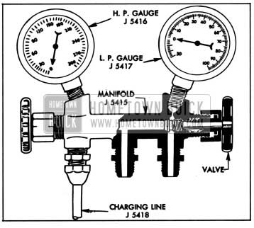
1957 Buick Pressure Gauge Set
NOTE: If a service replacement compressor is to be installed, both compressors must be drained of oil, and the same quantity replaced in the service compressor that was drained from the original compressor.
1957 Buick High and Low Pressure Service Fittings
Install compressor by reversing procedure for removal, paying attention to the following points.
- Inspect drive belt and pulley groove for conditions that might cause slippage. If the belt is cracked, frayed, or oil soaked, or is worn so that it bottoms in pulley groove, replace belt.
- Adjust drive belt to 3/8″ deflection midway between fan and compressor pulleys. See figure 10-10.
- Use new „O“ rings when attaching lines to compressor.
- Evacuate and charge system with 5 lbs. of Freon-12.
- After operating compressor for ten minutes at 1750 RPM, leak test around the line mounting plate.
Removal and Installation of Clutch and Pulley
Observing the precautions on handling Freon, remove compressor as per instructions contained in preceding paragraph, and transfer compressor to work bench. If service work is to be done with compressor on the car, see subpar. d.
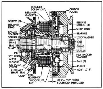
1957 Buick Clutch and Shaft Seal-Sectional View
- Bend the tangs on the shaft lock washer to clear the flats on the shaft mounting nut. Loosen the six screws in the clutch cover ring. Energize the clutch coil from a 12 volt D.C. source to hold the compressor shaft and clutch assembly. Remove the nut. Remove the metalfelt washer.
- Remove the six screws and lock washers used to mount the clutch cover ring to the pulley casting. NOTE: It is absolutely necessary that this be done at this time to avoid damage to the internal parts of the clutch. It may also be necessary to remove the three coil retaining screws to allow the clutch cover plate to move back.
- Remove the pulley and ball bearing assembly with Compressor Pulley Puller J-6351.
NOTE: The 1. D. of the ball bearing has a .0001″ to .0006″ press fit onto the first step of the compressor shaft.
- Remove the hub to pulley bearing spacer washer and shims and set aside.
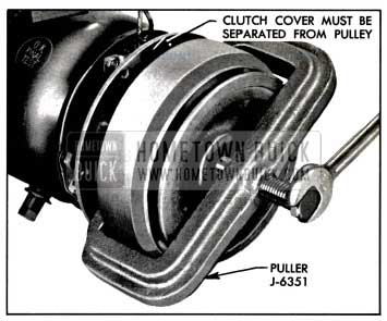
1957 Buick Removing Pulley
The clutch hub to bearing spacer washer and shims may be re-used on the assembly providing the original parts are being re-assembled. However, if it is necessary to replace either clutch plates, pulley, bearing, or if parts are being assembled on a service replacement compressor, a different combination of spacing shims may be required. This shimming is necessary to obtain the .008 to .013 clearance between the friction material on the clutch plate and pulley face, in the disengaged position.
NOTE: This clearance must be obtained before the clutch assembly and the pulley are pressed onto the shaft.
To obtain the clearance:
- Place the pulley and bearing assembly on a flat surface of the work bench.
- A combination of the shims listed here when used with the bearing spacer washer #5918343 (.088 +/- .002) will provide the .008 to .013 clearance.
- 5918366 – .010
- 5918367 – .015
- 5918368 – .020
- 5918369 – .025
- Select any suitable combination for trial use, and place these shims on the inner race of the ball bearing, then place the bearing spacer #5918343 on the shims. Now place the clutch plate assembly in the pulley, so that the hub is in contact with the spacer and shims.
Press down firmly at the center of the hub. Rotate the clutch plate assembly.
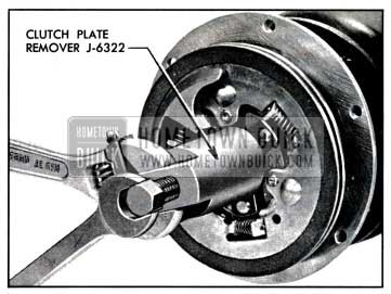
1957 Buick Removing Clutch Plates
If a very slight “drag” of the friction material is noticed, this will indicate that an insufficient thickness of shims is present in the assembly. Select a different combination and repeat check. If a heavy “drag” is felt, thicker shims must be selected in order to secure the very slight “drag.” If no “drag” at all is felt, thinner shims should be selected, to obtain the very slight “drag.” When this condition is obtained, determine the total thickness of the shims now assembled. Either add an additional .010 shim or replace one of the shims with a .010 thicker shim.
This will be the correct spacer and shim combination to complete the assembly to the compressor. After the clutch assembly is pressed on the shaft, place the thick spacer on first and then the correct thinner shims. This will prevent the shims dropping into the undercut near the shaft shoulder.
- Examine the O.D. of the shaft and the J.D. of the ball bearing for any evidence of wear, scoring or pitting (fretting corrosion). Replace ball bearing in pulley casting if necessary.
- To replace the ball bearing, remove the Truarc retaining ring, using Truarc pliers #3. Press out the ball bearing from the pulley and replace by pressing in a new bearing. NOTE: It is important upon reassembly to have the beveled side of the snap ring to the outside, or away from the ball bearing.
- The clutch plate assembly can now be removed by screwing on the special Clutch Plate Puller nut into which the Clutch Plate Puller screw has been assembled. (Tool J-6322). The cone point of this screw will center in the end of the compressor shaft. Rotate the screw with a wrench until the clutch plate assembly is pulled off of the shaft and woodruff key.
- Remove the woodruff key and air gap adjusting shims and spacer washer. Retain these parts for re-use, if the same clutch pulley parts are being reassembled. If clutch pulley parts are being transferred to a service replacement compressor, a different combination of shims may be required to obtain the .025 to .035 air gap between armature and coil housing when coil is energized by 12 volts D.C. The service replacement compressor clutch will have sufficient number of various thickness shims to obtain the correct air gap.
- Disassemble the actuating springs from the clutch plates. Examine the frictional surfaces for wear. Replace plate assemblies as necessary. Wipe plates with a clean, dry, oil free cloth. CAUTION: Do not use any cleaning solvents on the frictional surfaces, as it will result in unsatisfactory operation of the clutch upon reassembly. Examine the nylon balls that actuate the clutch. If any of the balls are deformed, excessively worn or damaged, replace all three.
- Install the three clutch coil retaining screws, place the clutch cover ring against the coil and seal housing.
- Install the clutch spacer and air gap control shims on the shaft against the shoulder. Replace the woodruff key, tapping it lightly to seat and properly align it.
- Reassemble the nylon balls and clutch plate springs to complete the assembly of the clutch plates.
- Align the key slot of the clutch hub with the woodruff key in the shaft of the compressor. Make very certain that this alignment is maintained during the next four steps.
- The clutch plate assembly is now ready to be pressed on the shaft, using tool J-6323. See figure 11-30.
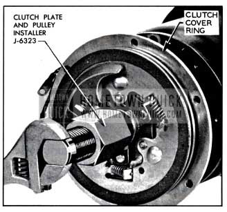
1957 Buick Installing Clutch Plates
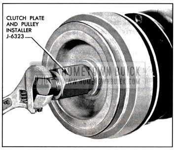
1957 Buick Installing Pulley
NOTE: This is important to prevent distorting or damaging the ball bearing, the grease seals, and prevent brinelling of the ball bearing. Screw the stud onto the threaded end of the compressor shaft. Turn the adapter with a wrench until the bearing and pulley assembly has been firmly pressed onto the shaft and into proper position. Remove assembly tool.
Removal and Installation of Clutch Coil and Shaft Seal
- Following instructions contained in preceeding steps 1 through 9 remove pulley and clutch.
- Disconnect the electrical leads of the coil from the terminal clip and ground screw.
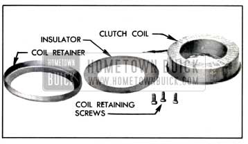
1957 Buick Clutch Coil Disassembled
The service replacement shaft seal assembly is supplied in a unit package. It contains the shaft seal, and seal seat, pin and retainer ring, and „O“ rings and auxiliary shaft seal, wiping tissues and packing list.
The old „O“ rings removed from the compressor should be discarded and replaced with the fresh ones contained in the unit package.
The shaft seal having the carbon block face and the polished metal seal seat should be handled very carefully to avoid damage to the fine finishes on their surfaces. When the seal seat retainer ring is replaced, use care not to scratch or mar the polished surface. Even when the seal surfaces are coated with oil, use care not to contact the seal surfaces with any metallic object, such as tip of oil can, rod, screw driver etc.
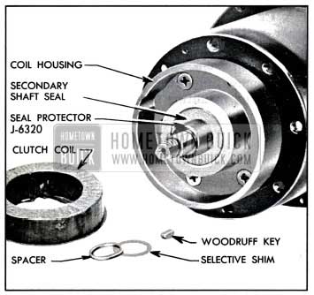
1957 Buick Secondary Shaft Seal and Protector
The lint-free tissues included in the replacement unit package should be used for the final cleaning of the shaft, seal cavity and parts. The seal cavity in the coil housing and around the auxiliary seal should be flooded with clean, fresh Frigidaire 525 viscosity oil prior to assembly. This oil should be taken out of the glass container, in which it is supplied. It is the same oil that is used in the compressor. No other oil should be used for this purpose. Coat all „O“ rings, seal faces and parts with this oil.
The shaft seal has an „O“ ring on the inside of it and will contact the O.D. of the compressor shaft when assembled. It must be protected when it is being placed over the shaft. To do this, place the shaft „O“ ring pilot bushing, J-6320, over the shaft against the second step. Apply a light coating of oil to the surface before sliding the seal and „O“ ring in place.
The auxiliary seal has a coating on the outer surface to effect a seal with the coil and seal housing when it is pressed into the coil housing. The inner flexible seal has a “V” shaped edge and is provided with a ring-shaped spring to apply the necessary sealing pressure to the shaft.
The inner lip of the auxiliary seal should be given a heavy coating of Frigidaire compressor oil and the space between the seal seat and the auxiliary seal in the coil housing should be flooded with the same oil.
Assemble the special pilot bushing, J-6320, into the auxiliary seal before assembling the coil and seal housing over the compressor shaft and to the compressor flange. Use care during this operation and also when removing the pilot bushing so as not to disturb the spring behind the “V” lip of the auxiliary seal. Carefully slide housing over shaft to compressor body making certain that the small oil drainback passage „O“ ring is not dislodged.
After the housing has been placed over the shaft and the „O“ ring end assembled to the compressor flange, install the six mounting screws.
The compressor seal should now be given a Freon-12 leak test to be sure the assembly has been properly made and is leak-tight prior to reassembly on the car.
It is suggested that a bar of metal similar to the service compressor shipping plate be made up for a cover plate over the suction discharge opening. Drill and tap plate in the area that will cover the suction or low pressure opening for either 1/8″ or 1/4″ pipe thread and screw in a 1/8″ pipe to a 1/4″ flare or 1/4” pipe to 1/4″ flare fitting and use two „O“ rings and the plate mounting bolt to seal the opening.
Connect a drum of Freon-12 to the fitting with a charging hose or copper line, which will pressurize the interior of the compressor and the compressor shaft seal. Leak test with leak detecting torch, around the shaft, seal, auxiliary seal and large diameter „O“ ring in the seal housing and the compressor flange.
Correct any leaks that may be found and proceed with reassembly of parts.
Assemble the inner insulator, actuating coil, outer insulator, coil retainer and the three screws in the coil housing.
The coil leads should be sealed with the sealing compound that was removed from the opening in the coil-seal housing. Proceed with steps 10 through 21 of subpar. b.
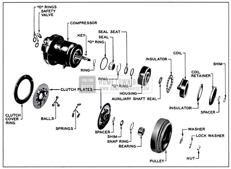
1957 Buick Clutch and Seal Exploded View
Before the compressor is reinstalled it should be checked to make certain it contains at least 4 oz. of compressor oil.
The compressor is now ready to be replaced on the engine mounting brackets. Connect the suction-discharge lines to the compressor using new „O“ rings from stock.
Proceed to evacuate or purge the air from the system, in accordance with previous service instructions. Charge with 5 lbs. of Freon-12.
Operate the engine and air conditioning system and check operation.
Remove test lines and gages and cap fittings on compressor.
Removal and Installation of Suction and Discharge Valve Parts
- Remove compressor from car as outlined in par. 11-8, sub. par. a. Also drain compressor oil into clean measured container to determine how much oil is still trapped in the system.
NOTE: Extreme care should be exercised when disassembling the compressor to keep internal parts free from dirt and moisture contamination. Do not keep it open any longer than necessary.
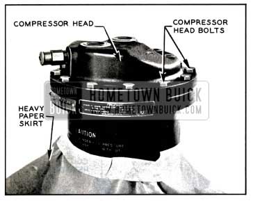
- Place compressor on clean bench in vertical position with weight resting on clutch pulley assembly.
- Tape heavy sheet of paper around compressor shell to form protective skirt to prevent oil from running down on clutch parts. See Figure 11-35.
1957 Buick Installing Clutch Protection
CAUTION: Some oil may be trapped in compressor head and if allowed to run into clutch will ruin clutch plates.
- Remove the 12 bolts which retain compressor head to body shell. Mark location of two long bolts which retain the muffler bracket. Upon reassembly these bolts must be installed in the same location. Then carefully lift head off body shell.
CAUTION: Extreme care must be exercised to lift head without any side movement or damage to bonded teflon gasket surface inside of head may result. See Fig. 11-36.
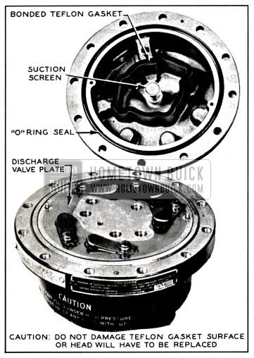
1957 Buick Removing Compressor Head
Be careful not to scratch or otherwise damage the teflon gasket as it seals the high pressure side of compressor from low pressure side. If gasket surface is damaged, the compressor head will have to be replaced.
- Using two screw drivers, carefully lift discharge valve plate from compressor body. See Fig. 11-37.
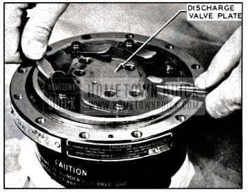
1957 Buick Removing Discharge Plate
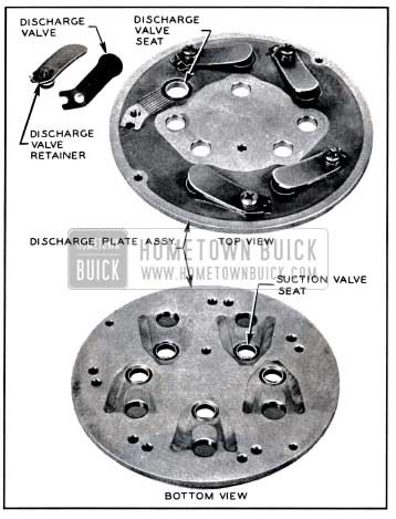
1957 Buick Discharge Plate Assembly
NOTE: Any damage to the valve seats, discharge valves or retainers will necessitate replacement of discharge plate assembly.
- If either suction or discharge reed is found to be broken, remove the thin suction reed plate without disturbing thrust washer at end of compressor main shaft. Carefully examine compressor head and cylinder for broken portions or metal particles. Remove all loose broken pieces.
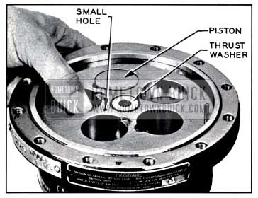
- Fully depress each piston to bottom dead center using thumb pressure and inspect each cylinder bore and piston head for damage. See figure 11-39.
1957 Buick Inspecting Cylinder Bores
- A normal condition will be indicated by a slight circular burnished wear pattern at this location. See View A, figure 11-40.
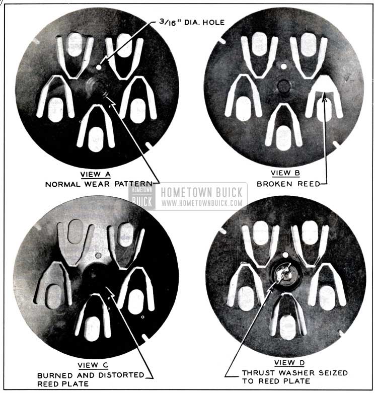
1957 Buick Suction Reed Plate
NOTE: If compressor cylinder walls are scored, piston heads damaged or if suction plate appears as shown in View C or D, fig. 11-40 it will be necessary to replace the complete compressor assembly. Also if compressor had been contaminated by moisture resulting in corrosion of internal parts of the compressor, it will have to be replaced. Reassemble compressor and cover valve opening in compressor head with shipping plate removed from new compressor. Old compressor should be returned properly tagged giving all pertinent information and stating on the tag that the compressor was opened for Field Inspection.
NOTE: It is a known fact the burned thrust washers result from operating the refrigeration system without having a full sight glass of liquid refrigerant. A shortage of Freon 12 does not permit normal oil return to compressor body, causing compressor to operate with insufficient lubrication.
Reassembly
- Before reassembling compressor, note that the bronze thrust washer extends slightly above the surface of the cylinder casting. This is normal due to the force of the spring in the shaft seal at the opposite end of the shaft.
CAUTION: Do not alter or change the relative position of the thrust washer and shims.
- Place the suction reed plate (thin) over the two dowel pins in the cylinder so that the 3/16″ dia. hole shown in View A, figure 11-40 which is approximately 3/4″ from the center of the plate, mates with the smaller hole in the cylinder block shown in figure 11-39. This hole is located between two of the piston bores.
- Install discharge plate (thick one) over the two dowel pins shown in_ figure 11-41.
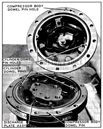
1957 Buick Installing Discharge Plate
NOTE: Coat ring with clean compressor oil before installing in the head casting.
- Place the brass ferrule end of the suction screen into the center of the head casting. Observe precautions concerning gasket material on center casting web.
- Grasp the head casting so that the suction screen will not fall out when the head is inverted for assembly. This can be accomplished by inserting the little finger through the center opening so as to hold the screen during assembly.
- The two cylinder dowel pins mating the head and mounted through the valve plates must be in proper alignment with the third dowel pin in the compressor body. This third dowel pin is located and mounted in the compressor body midway between two threaded screw holes. See figure 11-41.
CAUTION: Hold the compressor head over the compressor body flange so that cylinder dowel pin holes register as closely as possible with cylinder and compressor body dowel pins. Rotate the head slightly until exact dowel pin alignment is obtained, then carefully seat the head over the dowel pins and onto the compressor body. This will properly align the irregular shaped casting web that separates the high from low side to which is vulcanized the teflon gasket material. If this is not done properly, the teflon gasket material may be damaged by striking the discharge reed retainers or screws.
- When the head is properly aligned with the dowel pins, assemble all twelve cylinder head bolts so they are only FINGER-TIGHT. An initial torque of 3 to 5 ft. lbs. should first be applied to opposite bolts all around compressor head and then tighten in same sequence to specified 7 1/2 to 10ft. lbs.
NOTE: The procedure of tightening and torqueing these bolts is very important. If uneven or excessive torque is applied it will distort various parts and may decrease the end clearance of the shaft and cause a compressor failure because of burned thrust washer.
- Add the same amount of new compressor oil that was drained from the compressor in Step 1. Reassemble compressor to engine mounting in accordance with par. 11-8, sub. par. a.
Servicing the Compressor on the Car
- Preparation for Removing Compressor Shaft Seal.
- Attach gage set and charging lines and discharge system (sub. par. a.).
- Loosen compressor mounting bolts to relax belt; then remove belt from compressor pulley.
- Preparation for Removing Compressor Clutch Only.
When just the pulley and clutch and/or clutch coil are to be removed, only step b of the preceding section need be observed.
Adding Oil to Compressor and Checking Oil Level
NOTE: Checking or adding oil is not necessary unless there is positive evidence that a considerable quantity (4 oz. or more) of oil has been lost.
A stud fitting is welded into the compressor shell at the forward end, just behind mounting ring. The fitting is placed 43 degrees to the side of the vertical centerline. It is threaded on the inside to receive a screw that has a hole drilled in the center. Another hole is drilled at right angles to the center hole, and is just under the screw head. A copper gasket is used to seal the head to the stud.
The end of the stud and screw project through the shell and the opening into the screw is at the 4 ounce oil level.
The production compressor was originally charged with either 9 ounces or 12 ounces of 525 viscosity Frigidaire oil.
If a considerable quantity of oil has been lost through accident, or a leak of Freon and oil at any of the fittings has occurred, it is advisable to check the oil supply in the compressor.
Operate the engine at slow idle for 5 to 7 minutes with the air conditioning system turned on and the blower operating in High. Stop the engine and compressor.
Loosen the screw in the oil test fitting and allow a slight seepage of oil to escape. Then retighten the screw for a moment, then “crack” open slightly again. If a steady flow of oil is evident, the oil level is either at the safe minimum level of 4 ounces, or the compressor contains oil in excess of this, and could contain a full oil charge up to either 9 or 12 ounces.
NOTE: A service replacement compressor contains 9 ounces of 525 viscosity oil.
When the oil test screw was “cracked” open the second time and there was no oil escaping or a hissing or vapor only was evident, this indicates that the oil is below the safe minimum level and oil should be added to the compressor as per following instructions.
- Attach a gauge set to the proper connections on the compressor and discharge system.
- Remove compressor and drain oil reservoir into a clean container.
- If oil is clean proceed with step No. 4; if oil is dirty flush both compressor and condenser with liquid Freon until clean.
- Pour 9 oz. of new 525 viscosity Frigidaire compressor oil into compressor through oil checking fitting.
- Replace checking screw and replace compressor.
- Connect all hoses and fittings and evacuate and charge with 5 lbs. of Freon 12.
- Leak test and perform functional test.
11-9 EVACUATION AND CHARGING
Evacuation of System with Vacuum Pump
- Attach gauge lines and vacuum pump set-up as shown in figure 11-42 and discharge any Freon that may be left in the system.
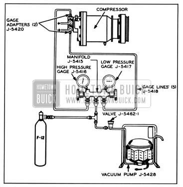
1957 Buick Service Charging Hook-up
Charging the System
- With the vacuum pump, Freon-12 cylinder and gauge set connected to the compressor as shown in Figure 11-42, place the cylinder in a bucket of hot water which does not exceed 125°F.
CAUTION: Do not heat Freon-12 cylinder above 125° F. because the fusible safety plug in cylinder valve melts at 157°F and softens at a slightly lower temperature.
- Place cylinder and bucket on a suitable scale and record the total weight.
- Open the low pressure valve on the gauge set. (High pressure valve on gauge set closed.)
- Wearing goggles to protect eyes, fully open the Freon-12 cylinder valve and allow Freon-12 vapor to flow into the refrigerating system.
- Operate engine and compressor at slow idling speed until a total of 5 pounds of Freon-12 have been charged into the system.
NOTE: It may be necessary to reheat the water in bucket to maintain required pressure.
- Close both valves on gauge set, close valve on Freon-12 cylinder, and remove cylinder from bucket of water.
- Operate the compressor with engine running at 1750 RPM (using tachometer) and observe general performance of Air Conditioner. If performance is satisfactory, stop the engine.
- With engine off remove gauge lines and cap compressor fittings.
11-10 FUNCTIONAL TEST
Test Conditions: Hood closed, doors open, heater Ranco valve off, Air Conditioner controls set for “Max” cooling and no sun load. If ambient temperature is below 80° or if humidity is high it is advisable to provide forced circulation of air through the condenser by large fan, blower or other means.
Extreme humidity conditions may make the functional test results erratic.
NOTE: Set Engine Speed as designated for each corresponding ambient temperature.
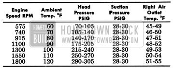
1957 Buick Engine Speed Air Outlet Temperatures
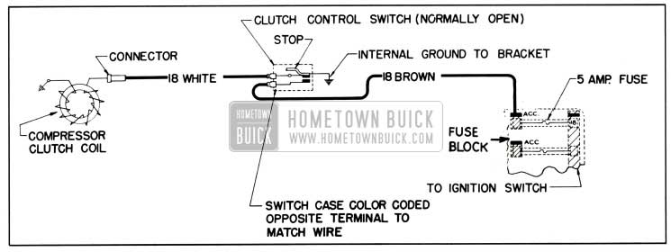
1957 Buick Clutch Coil Wiring Diagram
Leave A Comment
You must be logged in to post a comment.