SECTION 7-C 1957 BUICK CHASSIS SUSPENSION SERVICE, ADJUSTMENT, AND REPLACEMENT PROCEDURES
7-8 1957 BUICK TIRE SERVICE AND INSPECTION
1957 Buick Tire Inflation and Inspection
Maintenance of correct inflation pressure in all 1957 Buick tires is one of the most important elements of tire care. Correct tire pressure is also of great importance to ease of handling and riding comfort. Overinflation is detrimental to tire life but not so much as underinflation. Inflate all tires according to tire temperature as specified in paragraph 1-1.
Driving without valve caps contributes to underinflated tires. The valve cap keeps dirt and water out of the valve core and seals the valve against leakage. Whenever tires are inflated be sure to install valve caps and tighten firmly by hand. Make sure that rubber washer in cap is not damaged or missing.
If tires are checked at frequent intervals and adjusted to correct inflation pressure, it is often possible to detect punctures and make a correction before a tire goes flat, which may severely damage tire and tube if car is in motion. Slight differences in pressure between tires will always be found, but a tire that is found to be 3 or more pounds below the lowest of its running mates can be suspected of having a leaking valve or a puncture.
All 1957 Buick tires should be inspected regularly to avoid abnormal deterioration from preventable causes. If tires show abnormal or uneven wear the cause should be determined and correction should be made.
See that no metal or other foreign material is embedded in the tread. Any such material should be removed to prevent damage to tread and tire carcass. Cuts in a tire which are deep enough to expose the cords will allow dirt and moisture to work into the carcass and ruin the tire unless promptly repaired.
1957 Buick Tubeless Tire Repairs
A leak in a tubeless tire may be located by inflating the tire to recommended pressure (par. 1-1) and then submerging tire and wheel assembly in water, or by applying water to tire with a hose if wheel is mounted on car. Remove water from area where air bubbles show and mark the area with crayon. After removal of the puncturing object from tire, the puncture must be sealed to prevent entrance of dirt and water which would cause damage to the tire carcass.
A small puncture of less than 3/32″ diameter may be sealed without removal of tire from wheel by injecting sealing dough with a gun. Punctures up to 1/4” diameter may be sealed by installation of a rubber plug with cement, after tire has been removed from wheel. Sealing dough with gun, and rubber plugs with cement are contained in tire repair kits available through tire dealers. These materials should be used as directed in the instructions supplied with the kits. If a puncture is larger than 1/4″ or there is other damage to the tire carcass, repairs should be made by authorized tire dealers in accordance with instructions of the tire manufacturer.
Demounting and Mounting of 1957 Buick Tubeless Tire
When demounting a tubeless tire use care to avoid damaging the rim-seal ridges on tire beads. A “bead breaker” is recommended for loosening the beads. DO NOT USE TIRE IRONS TO FORCE BEADS AWAY FROM WHEEL RIM FLANGES. After both beads are broken loose from wheel rim flanges, remove tire in usual manner, starting at the valve stem, and using care to avoid damaging rim seal ridges.
When tire is removed, inspect it carefully to determine whether loss of air was caused by puncture or by improper fit of beads against rim flanges. If improper fit is indicated, check wheel as follows:
- Straighten wheel rim flanges if bent or dented.
- Clean rims thoroughly, using No. 3 coarse steel wool, to remove all oxidized rubber, soap solution, etc. Remove rust with wire brush.
- Inspect butt weld and other areas of rim contacted by tire beads, to make certain there is no groove or high spot. Remove any groove or high spot by filing smooth.
- Inspect valve stem and replace it if damaged. Make certain that valve stem is properly installed to provide an air tight joint.
Before mounting a tubeless tire on a wheel remove cardboard spacer, if tire is new. Moisten a cloth with mounting compound or soap solution and wipe rim-seal ridges of both beads to remove all foreign substance. Moisten base of both beads with mounting compound or soap solution to help beads snap into place when tire is inflated. Start tire over rim flange at point diametrically opposite valve stem, so that valve stem cannot prevent bead from dropping into the well as last section of bead is forced over the rim flange. Align balance mark on tire with valve stem.
Either a tire mounting machine or tire irons may be used; however, parts of tools contacting tire beads must be smooth and clean to avoid damaging rim-seal ridges. Take small bites if tire irons are used. DO NOT USE HAMMERS.
CAUTION: Due to the violence with which the outer bead seats to the rim, it is recommended that an extension gage with a clip-on chuck be used for mounting inflation. This will allow the operator to remain at a safe distance.
Remove valve core to increase flow of air during inflation. Hold tire and wheel assembly in vertical position and bounce on floor at various points around circumference to snap beads out against rim flanges. If a seal cannot be effected in the foregoing manner with the rush of air, apply a tourniquet of heavy sash cord around circumference to tire and tighten it with a tire iron to force beads outward.
Inflate tire until both beads are firmly seated against rim flanges, then remove air chuck, insert valve core and temporarily inflate to 50 pounds pressure. Leak test wheel and tire assembly under water, and if satisfactory reduce to recommended pressure (par. 1-1).
Interchanging 1957 Buick Tires
Tires tend to wear unevenly and become unbalanced as mileage accumulates. Uneven tire wear is frequently the cause of tire noises which are attributed to rear axle gears, bearings, etc., and work is sometimes needlessly done on rear axles in an endeavor to correct the noise.
Tire life will be increased and uneven wear and noise will be less likely to occur if the tires, including the spare, are balanced and interchanged at regular intervals of approximately 5000 miles. The recommended method of interchanging tires is shown in figure 7-7.
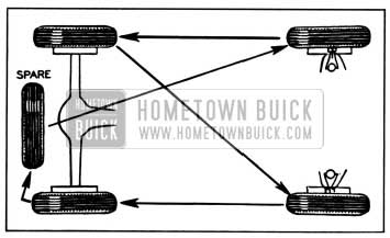
1957 Buick Method of Interchanging Tires
Use of Tire Chains on a 1957 Buick
Do not use tire chains on the front wheels under any circumstances because they will interfere with the steering mechanism. Any of the conventional full-type non-skid tire chains can be used on the rear wheels.
Tire chains should be loose enough to “creep” but tight enough to avoid striking fenders or other parts. If chains remain in one position the tire side wall will be damaged. Tension springs (either metal coil springs or the rubber band type) must also be used in order to prevent chains contacting frame, etc. The use of tension springs will also reduce ordinary chain noise caused by loose cross links contacting pavement.
7-9 REPLACE AND ADJUST 1957 BUICK STABILIZER LINK GROMMETS
The construction of the 1957 Buick stabilizer links is clearly shown in figure 7-8.
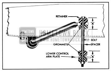
1957 Buick Front Stabilizer Link-Sectional View
To disassemble, remove nut from lower end of the link rod, then remove rod, spacer, retainers, and grommets. When new, the link grommets are 7/8″ free length. When assembling, install rubber grommets dry and use care to center the grommets in the seats on stabilizer shaft and lower control arm plate, also center the retainers on grommets before tightening rod nut. Tighten rod nut to the limit of thread on rod.
When the rod nut is tightened to limit of threads on rod, the overall dimension between sides of grommet retainers as shown at “A” in figure 7-8 should be 1 11/16″. If dimension “A” is not 1 11/16″ when nut is tight, adjust the nut to obtain this dimension. This is important to insure proper riding qualities and stabilization.
7-10 REPLACE AND ADJUST 1957 BUICK FRONT WHEEL BEARINGS
Replacement of Bearings
- Remove wheel with hub and drum assembly. Remove oil seal packing from hub so that inner bearing can be properly cleaned and inspected.
- Wipe old grease out of hub and from steering knuckle spindle. Clean and inspect all bearing parts as described under Bearing Service (par. 1-10), and replace any that are faulty.
- If a bearing cup has to be replaced, drive the old cup out with a punch. Use care when installing the new cup to start it squarely into hub, to avoid distortion and possible cracking.
- When inspecting or replacing bearing cones (inner races) make sure that cones are free to creep on spindle of steering knuckle. The cones are designed to creep on the spindle in order to afford a constantly changing load contact between the cones and the ball bearings. Polishing the spindle and applying bearing lubricant will permit creeping and prevent rust forming between cone and spindle.
- Wash and thoroughly dry all bearing parts, because wheel bearing lubricant will not adhere to oily surfaces.
- Thoroughly pack both ball bearing assemblies with new wheel bearing lubricant, preferably using a bearing packer. If packer is not available, work lubricant into bearings by hand. In either case, remove any surplus lubricant.
- Apply a light coating of lubricant to spindle and inside surface of wheel hub to prevent rusting.
- Place inner bearing assembly in cup and install a new oil seal, driving seal squarely into hub to avoid distortion. Carefully install inner bearing cone in oil seal. NOTE: Never place cone on spindle because seal will be damaged as wheel is installed.
- Install wheel on spindle, then install outer bearing assembly, cone, safety washer and nut. See figure 7-9.
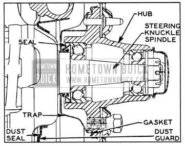
1957 Buick Front Wheel Hub and Bearings
Adjustment of 1957 Buick Front Wheel Bearings
- Tighten spindle nut with 10″ wrench until bearings are preloaded at least one hex, then rotate wheel one revolution to make sure bearings are seated.
- Back off spindle nut until bearings are slightly loose. Tighten nut until all bearing looseness is just removed, then line up nut to nearest cotter hole and install cotter pin. Do not mistake loose king pin bushing, etc., for wheel bearing looseness. CAUTION: Bearing preload must not exceed ¥12 turn of spindle nut.
- Before installation of grease cap in hub, make sure that end of spindle and inside of cap are free of grease so that radio static collector makes a good clean contact. Make sure that static collector is properly shaped to provide good contact between end of spindle and the grease cap.
7-11 REMOVAL AND INSTALLATION OF 1957 BUICK BALL JOINTS AND/OR STEERING KNUCKLE
Removal of 1957 Buick Ball Joints and Steering Knuckle
- Jack up car and support weight on front spring seat.
- Remove front wheel with hub and drum assembly.
NOTE: Support wheel assembly carefully during removal to avoid damaging wheel bearing inner seal.
- Remove bolts through backing plate and steering knuckle.
- Remove backing plate from knuckle. Do not remove brake hose. Support backing plate out of way to avoid damage to brake hose.
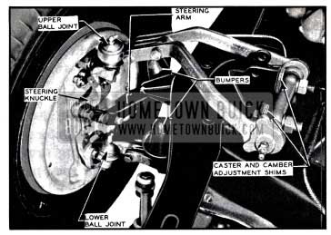
- Remove bolts through lower control arms and ball joint. Lower steering arm out of the way. Remove rubber bumper from ball joint if ball joint is to be replaced.
- Remove bolts through upper control arms and ball joint. Remove knuckle and ball joint assembly from upper and lower control arms.
- Support securely in vise in a manner that will allow solid blows directly on the end of the ball joint stud. See Figure 7-10.
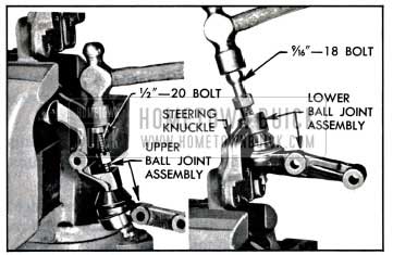
1957 Buick Removing Ball Joints from Steering Knuckle
NOTE: If ball joints are to be replaced, drive directly on studs to remove. If knuckle is to be replaced and ball joints are to be reinstalled, care must be taken to avoid damage to threads. Loosen nuts on tapered studs and install a short bolt half way into nut and tighten. The upper ball joint stud has a 1/2″-20 thread which is the same as a universal joint bolt. The lower stud has a 9/16″-18 thread, the same as a wheel lug bolt.
Installation of 1957 Buick Ball Joints and 1957 Buick Steering Knuckle
- Wipe clean and lightly lubricate the tapered surfaces of the ball joints and knuckle. Install joints in knuckle and tap lightly with a hammer. Install nuts and torque upper nut 30-40 ft. lbs. and lower nut 40-50 ft. lbs.
- Position ball joint and knuckle assembly in upper and lower control arms and install bolts.
NOTE: Bumper pad mounts to rear side of upper control arm assembly. Torque bolts to 70-80 ft. lbs.
- Install rubber bumper in lower ball joint, if removed during servicing.
- Using a new dust seal, reinstall steering arm and brake backing plate on knuckle.
NOTE: Steering arm to knuckle bolts require castellated nuts and cotter pins.
- Examine inner wheel bearing seal and grease trap for evidence of damage or leaking. If necessary, install new seal using Hub Oil Seal Installer J-6414.
- Reinstall wheel and hub assembly.
7-12 REMOVAL AND INSTALLATION OF UPPER CONTROL ARM SHAFT OR ARM AND SHAFT ASSEMBLY
Removal
NOTE: As upper control arms are not furnished separately, their replacement must be made as an assembly.
- Jack up car, supporting car weight on spring seat and remove wheel and tire.
- Remove upper control arm to ball joint bolts, supporting knuckle and brake drum assembly to avoid damage to brake hose.
- Remove shock absorber upper mounting bolt and force top of shock absorber down.
NOTE: If work is being performed on right side it will be necessary to remove generator and generator mounting bracket. (Disconnect battery ground strap.)
- Remove shaft attaching bolts, carefully noting position and number of adjusting shims. Remove arm and shaft assembly from car.
- If upper shaft and bushings only need replacement, clamp arms in vise, and remove old shaft and bushings; then apply a liberal amount of Lubriplate to new bushings and ends of shaft. Install bushings and tighten to 150 ft. lbs. torque. Install grease fittings.
- Install rubber dust seals on shaft and screw shaft into forward arm to 1 9/16″ (+/- 1/32″) dimension shown in Figure 7-6. Thread rear arm onto shaft to the 7 13/16″ (+/- 1/16″) dimension. See Figure 7-11.
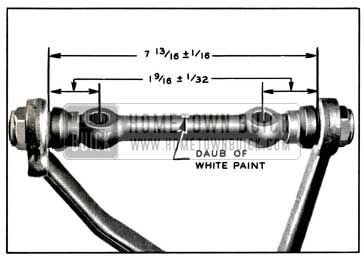
1957 Buick Upper control Shaft Dimensions
Installation
- Using care not to disturb dimensions obtained in Step 6, install assembly on car by reversing removal procedure. Tighten upper ball joints bolts to 70-80 ft. lbs. torque. Tighten upper shaft to shaft bracket nuts 90-100 ft. lbs.
- Check front wheel alignment and correct as necessary.
7-13 CHECKING AND REPLACING 1957 BUICK CHASSIS SPRINGS
Checking Spring Trim Dimensions
Optional equipment, undercoating, etc., changes the car weight and must be considered when checking spring trim dimensions. Because of the many possible variations in loading due to optional equipment it is not possible to give dimensions for all; therefore, the spring trim dimensions given below are for the standard car only, without optional equipment or undercoating and with car at curb weight. Curb weight includes gas, oil, water, and spare tire but no passengers.
Before measuring spring trim dimensions, bounce both ends of car up and down several times to make sure there is no bind in suspension members, and to let springs take a natural position. When car is at rest, measure the trim height at point “A” for front spring or point “B” for rear spring, as indicated in figure 7-12.
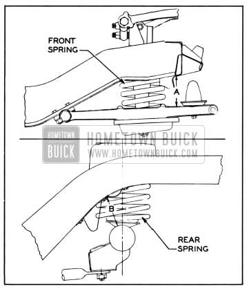
1957 Buick Spring Trim Dimensions
- Front Springs. On a car having service miles the front spring trim dimension “A” should be within the following limits, with car at curb weight.
- 46C, 66C, 56C, 76C: 4” – 4 1/2”
- All other models: 4 1/4” – 4 3/4”
- NOTE: When checking NEW car add 1/4”
When the trim dimension is found to be too low, correction may be made by installing special shims (Group 7.425), 1/8″ thick, between upper end of spring and the frame. If more than three shims are required, replace the spring.- Rear Springs. On a car having service miles the rear spring trim dimension should be within the following limits, with car at curb weight.
- 46C, 46R, 56C, 56R, 66C, 66R, 76C, 76R: 4 5/8″ – 5 5/8″
- 48, 49, 69: 5 1/2” – 6 1/2”
- All other models: 5 1/8” – 6”
- NOTE: When checking NEW car add 3/8″
If trim dimension is less than specified or additional height is required to prevent excessive “bottoming” in exceptional cases, install additional spring insulators (group 7.545), divided between upper and lower ends of spring. If more than three additional shims are required replace the spring. Installation of new springs should not increase spring trim dimension “A” more than 1″ over specified maximum limit.
Removal and Installation of 1957 Buick Front Spring
- Place jack under lower control arm, raise wheel off floor, and remove wheel and tire assembly.
- Disconnect stabilizer link and disconnect outer end of the tie rod from steering arm.
- Remove shock absorber (par. 7-15).
- Remove upper ball joint to control arm attaching bolts.
- Support car frame by another jack, then slowly lower the jack under lower control arm. This will allow lower control arm to drop low enough to remove 1957 Buick chassis spring without damaging the brake hose.
NOTE: It may be necessary to remove the brake pipe clip and move the pipe slightly to gain enough slack.
- Before installation of front spring, check the part number which is stamped on one end coil to make sure that spring is correct for the car model, as specified in Group 7.412 of Master Parts List.
- Make sure that the rubberized fabric spring insulator is in place around the spring centering flange on frame and is in good condition.
- Place one end of spring over the centering flange, and as lower control arm is raised, position lower end of spring so that the end coil seats in the recess provided in spring seat. Support lower control arm on a jack.
- When the lower control arm is raised far enough, install the two upper ball joint to control arm bolts with the upper bumper pad to the rear. Torque bolts 70-80 ft. lbs.
- Connect tie rod outer end to steering arm, and connect stabilizer link. Adjust stabilizer link grommets as described in paragraph 7-9.
- Reinstall 1957 Buick shock absorber (par. 7-15).
- Install wheel and tire assembly, then check and adjust caster, camber, and toe-in (par. 7-17).
Removal and Installation of 1957 Buick Rear Spring
- Disconnect both 1957 Buick rear shock absorber lower ends.
- Hoist rear end of car until all load is off rear springs and place floor stands under frame for safety.
- Remove spring clamps at lower and upper ends and remove spring.
- Check part number stamped on one end coil of new spring to make certain that spring is correct for the car model as specified in Group 7.503 of Master Parts List.
- Be sure that spring insulator in upper seat is in good condition then attach upper end of spring using spring clamp, bolt insulator, flat washer, lockwasher and bolt in the order named. Attach lower end of spring with spring clamp, lockwasher and nut.
- Lower rear end of car and attach lower ends of shock absorbers. NOTE: Car weight must be on rear wheels when tightening shock absorber ends to clamp rubber bushings in a neutral position.
Use of Special Overload Rear Springs
Special 500 pound overload rear springs are available for service installation in cases where heavy loads are carried or heavy trailers are towed. Overloading any series rear axle in excess of 500 pounds is not recommended.
In estimating rear spring overloads, place rear wheels of car on scale, with car at curb weight and no load in rear compartment other than spare wheel and tire. After obtaining weight, hook trailer to car, or place desired load in rear compartment, and read scale again. The additional weight is the amount of overload on springs and rear axle.
Trailer design, and distance that trailer coupling is located to rear of rear axle center line, are the major factors governing effective trailer overload. Instructions for attaching trailers to Buick cars may be obtained from Buick Motor Division Factory Service Department.
7-14 REPLACE OR REBUSH 1957 BUICK LOWER CONTROL ARM ASSEMBLY
If a lower control arm is bent or broken it should be replaced with a new assembly which includes the shaft, bushings, and dirt seals. The riveted parts of the assembly are not furnished separately. If only the shaft and bushings require replacement these can be obtained separately.
Use all of the following steps for replacement of control arm shaft and bushings. Use only steps 1, 9 and 10 for replacement of control arm and shaft assembly.
- Remove front chassis spring (par. 7-13) then remove lower control arm assembly from frame front cross member.
- Unscrew bushings and remove shaft from control arm.
- Check the distance between inner ends of control arm. The normal dimension is 11 1/4″ plus or minus 1/32″, from inside to inside. See figure 7-14.
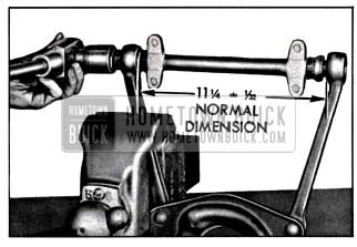
1957 Buick Installing First Bushing
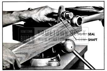
1957 Buick Springing Arm Over End of Shaft
NOTE: Apply a liberal amount of white lead or Lubriplate to both bushings before installing in arms.
7-15 1957 BUICK SHOCK ABSORBER SERVICE AND REPLACEMENT
Checking 1957 Buick Shock Absorbers
Both front and rear shock absorbers are filled and sealed in production and cannot be refilled in service.
Removal and Installation of 1957 Buick Front Shock Absorber
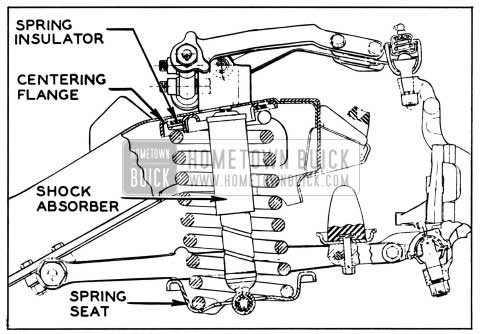
1957 Buick Front Spring and Shock Absorber Installation
- Raise car by center of front frame cross member far enough to allow removal of upper shock absorber bolt. Remove bolt and shove mounting eye down through opening in frame.
- Remove bolts and lockwashers attaching lower mounting bracket to spring seat on lower control arm, then pull shock absorber assembly down through opening in spring seat.
- Inspect upper and lower rubber bushings. If rubber bushings are not in good condition or if shock absorber is faulty, the complete unit must be replaced.
- Make certain that shock absorber being installed is correct for car model as indicated by part number stamped on the outer tube. See Master Parts List Group 7.345 for standard and optional parts.
- Insert shock absorber through opening in lower control arm spring seat and mounting eye up through opening in mounting bracket on frame.
- Install upper bolt with nut forward and torque nut 25 to 35 ft. lbs.
- Bolt lower mounting bracket securely to lower control arm spring seat and lower car.
Removal and Replacement of 1957 Buick Rear Shock Absorber
- Remove lower shock absorber mounting eye bolt, nut, washer, spacer and rubber bushings.
- Remove upper shock absorber mounting eye bolt, nut, spacer and rubber bushings. Remove shock absorber.
- Inspect all rubber bushings and replace if not in good condition. If shock absorber operation is faulty, it must be replaced as it cannot be repaired.
- Make certain that new shock absorber is correct for car model as indicated by part number stamped on the outer tube. See Master Parts List Group 7.345 for standard and optional parts.
- Place spacers and rubber bushings in shock absorber mounting eyes. Hold shock absorber in position and install pivot bolts and nuts.
- Lower rear end of car. Then tighten pivot bolts until brackets are tight against ends of spacer. NOTE: Car weight must be on rear wheels when tightening shock absorber ends to clamp rubber bushings in a neutral position.
Shock absorber calibrations as furnished in production have been carefully engineered to provide the best ride control over a wide range of driving conditions. Substitution of other calibrations should not be attempted under any circumstances, unless authorized by Buick Motor Division.
7-16 1957 BUICK WHEEL AND TIRE BALANCE
Wheel and tire balance is the equal distribution of the weight of the wheel and tire assembly around the axis of rotation. Wheel unbalance is the principal cause of tramp and general car shake and roughness, and contributes somewhat to steering troubles.
All 1957 Buick wheel and tire assemblies are balanced when assembled at the factory. After installation of tire on the wheel, the assembly is further corrected for balance, if necessary, by installing balance weights on the rim of the wheel.
The original balance of the tire and wheel assembly may change as the tire wears. Severe acceleration, severe brake applications, fast cornering and side slip wear the tires out in spots and often upset the original balance condition and make it desirable to rebalance the tire and wheel as an assembly. Tire and wheel assemblies should be rebalanced after punctures are repaired.
Because of the speed at which cars are driven it is important to test the wheel and tire assembly for dynamic balance. Dynamic balancing of a wheel and tire assembly must be done on a machine designed to indicate out of balance conditions while the wheel is rotating. Since procedures differ with different machines, the instructions of the equipment manufacturer must be carefully followed.
In some cases wheel and tire balance does not always overcome wheel balance complaints because the brake drums themselves are out of balance. Balancing drums with wheels and tires as an assembly is not always satisfactory because the balance is destroyed when wheels and tires are removed or interchanged. On cars where trouble is experienced in maintaining proper wheel balance, it is suggested that all drums be individually checked for static balance and corrected, if necessary, as described under Brake Drum Balance (par. 9-12).
7-17 1957 BUICK FRONT WHEEL ALIGNMENT
Wheel alignment is the mechanics of properly adjusting all the factors affecting the position of front wheels so as to cause the car to steer with the least effort and to reduce tire wear to a minimum.
Correct alignment of the frame is essential to proper alignment of front and rear wheels. Briefly, the essentials are that the frame must be square in plan view within specified limits, that the top and bottom surfaces of front cross member must be parallel fore and aft, and the bolt holes for support upper arms and lower control arm shafts must be of correct size and location. Checking frame alignment is covered in Group 12.
It should also be understood that wheel and tire balance has an important effect on steering and tire wear. If wheels and tires are out of balance, “shimmy” or “tramp” may develop or tires may wear unevenly, and give the erroneous impression that the wheels are not in proper alignment. For this reason, the wheel and tire assemblies should be known to be in proper balance before assuming that wheels are out of alignment.
Close limits on caster, front wheel camber, and theoretical king pin inclination are beneficial to car handling, but require only reasonable accuracy to provide normal tire life. With the type of front suspension used, the toe-in adjustment is much more important than caster and camber in so far as tire wear is concerned. Caster and camber adjustments need not be considered unless visual inspection shows these settings to be out, or unless the car gives poor handling on the road.
In the majority of cases, services consisting of inflating tires to specified pressure and interchanging tires at recommended intervals (par. 7-8), balancing all wheels and tires (par. 7-16) adjusting steering gear (par. 8-4), and setting toe-in correctly (subpar. e, below) will provide more improvement in car handling and tire wear than will front end alignment adjustments as usually made on front end alignment equipment.
The use of accurate front end alignment is essential to determine whether front suspension parts have been damaged by shock or accident, and to obtain correct alignment settings after new parts have been installed.
Inspection Before Checking 1957 Buick Front Wheel Alignment
Before any attempt is made to check or make any adjustment affecting caster, camber, toe-in, theoretical king pin inclination, or steering geometry, the following checks and inspections must be made to insure correctness of alignment equipment readings and alignment adjustments.
- The front tires should have approximately the same wear and all tires must be inflated to specified pressures (par. 1-1).
- Check front wheel bearings for looseness and adjust, if necessary (par. 7-10).
- Check for run-out of wheels and tires and correct to within limit of 1/8″ run-out at side of tires, if necessary.
- Check wheels and tires for balance and correct if out of balance (par. 7-16).
- Check for looseness at upper ball joints and tie rod ends; if found excessive it must be corrected before alignment readings will have any value.
- Check shock absorber action and correct, if necessary (par. 7-5).
- Car must be on a level surface. Place a 3/8″ square pin 3 21/32″ long between the frame and front lower control arm at each front wheel as shown in Figure 7-16, making sure that the pin is standing vertical and not leaning. Use sandbags or other suitable weight when necessary to hold car down on pins.
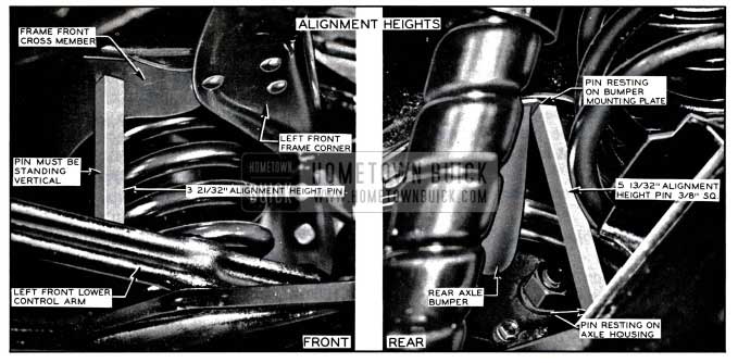
1957 Buick Springs Alignment Heights
1957 Buick Springs Specifications Chart
Checking Caster and Camber Settings
Since caster and camber are both adjusted by shimming in the same locations, both of these settings must be checked before changing either setting.
CAUTION: Regardless of equipment used to check caster and camber, car must be on level surface both transversely and fore and aft. Since camber and caster vary in proportion to the height of the front springs, it is very important that the correct alignment height is maintained while checking. (par. 7-17a.).
Alignment height is used only when checking and adjusting caster and camber and should not be confused with trim height which is used to establish proper spring dimensions.
When equipment is used which bears against the tire or wheel rim to obtain readings, it is very essential that the tires or wheels be checked for run-out. Readings must be taken at points which have no run-out or which lie in the same plane.
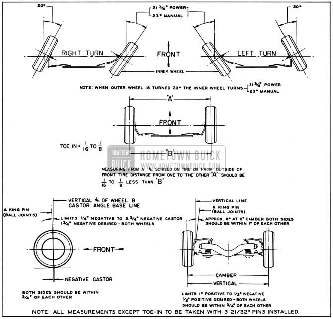
Caster and camber should be within the limits shown in figure 7-16. Note that the caster angles at both front wheels need not be exactly the same but must be within 1/2 degree of each other. Likewise, the camber angles on both sides must be within 3/4 degrees of each other. If caster and camber are not within the specified limits, adjust as described below.
Adjustment of Caster and Camber
Caster and camber may be adjusted by shimming at either the upper or lower control arm shaft attaching points. If only a small adjustment is needed to bring alignment within limits, lower control arm shaft shimming should provide sufficient adjustment. If a major adjustment is needed, shimming at the upper control arm shaft is recommended.
Production adjustment is done at the upper shaft locations using shims of .060”, .080″ and .100”. The .080″ shims are copper-plated for identification. Both round (non-removable) and horseshoe (removable) shims are used and at least one of the horseshoe type is used in each of the four upper locations. The horseshoe shims are listed under Group 6.178 of the Master Parts list. No lower control arm shaft shims are installed in production but are available under Group 6.172 in thicknesses of .040″ and .120″.
Adding shims at the front locations (either upper or lower shaft) will change caster toward negative with practically no change in camber. Adding shims at the rear locations (either upper or lower shaft) will change caster toward positive and camber toward negative. Adding equal shims at both front and rear locations, (either upper or lower shaft) will not change caster but will change camber toward negative.
Lower control arm shimming requires loosening the bolts (lower control shaft to frame), one end of shaft at a time, and installing or removing shims between shaft mounting lugs and frame. Maximum shim stack thickness at any one lower location must be limited to .160″. Tighten and torque all bolts, re-check alignment and correct toe-in if necessary. NOTE: Whenever shims are added at the lower locations, 300M bolts (7/16″-20″-1 3/4,” long) must be used.
1957 Buick Upper Control Arm Shims
To shim at the upper control arm shaft locations, it is necessary to wedge the bolt heads to prevent turning, and loosen both bolts to free the shims for removal or replacement. On the right side the generator must be removed with mounting bracket and the fender inner skirt must be forced outward to provide clearance for wrenches. On the left side it is recommended to disconnect the battery negative cable.
After installing or removing upper shims (limit .380″ in any one stack) tighten and torque upper shaft bolts and re-check alignment before installing generator, etc. If alignment is within limits replace generator bracket and generator and connect battery negative cable. Correct toe-in if necessary. It is imperative to adhere strictly to the torque specifications given in paragraph 7-1.
Checking Theoretical King Pin Inclination
CAUTION: When checking theoretical king pin inclination, car must be on a level surface, both transversely and fore and aft. It must be maintained at specified alignment height while checking (par. 7-17a).
With camber known to be within specified limits, theoretical king pin inclination should check within specified limits given in figure 7-16.
If camber is incorrect beyond limits of adjustment and theoretical king pin inclination is correct, or nearly so, a bent steering knuckle is indicated.
If camber and theoretical king pin inclination are both incorrect by approximately the same amounts, a bent upper or lower control arm is indicated.
There is no adjustment for theoretical king pin inclination as this factor depends upon the accuracy of the front suspension parts. Distorted parts should be replaced with new parts. The practice of heating and bending front suspension parts to correct errors is not recommended as this may produce soft spots in the metal in which fatigue and breakage may develop in service.
Checking and Adjusting Toe-In
CAUTION: Car must be at curb weight and running height, (DO NOT USE ALIGNMENT PINS-bounce front end and allow it to settle to running height). Steering gear and front wheel bearings must be properly adjusted with no looseness at tie rod ends. The car should be moved forward one complete revolution of the wheels before the toe-in check and adjustment is started and the car should never be moved backward while making the check and adjustment.
- Turn steering wheel until lower spoke is vertical, with front wheels in straight ahead position.
- Measure the horizontal distance from the near edge of front boss of lower control arm shaft to the front edge of brake backing plate, on each side. Adjust tie rods, if necessary, to make measurements equal on both sides.
- Using a suitable toe-in gauge, measure the distance between outside walls of tires at the front at approximately 10″ from the floor. See figure 7-16 dimension “A.” Mark points where gauge contacts tires. NOTE: An accurate check also can be made by raising and rotating front wheels to scribe a fine line near the center of each tire, then, with tires on the floor and front end at running height, measure between scribed lines with a suitable trammel.
- Roll the car forward until measuring points on tires are approximately 10″ from the floor at the rear, and measure the distance between points used in Step 3 above. The measurement at the front (dimension “A”) should be 1/16″ to 1/8″ less than the measurement at the rear (dimension “B”). See figure 7-16.
- If toe-in is not within specified limits, loosen clamp bolts and turn adjusting sleeves at tie rod ends as required. Decrease toe-in by turning left sleeve in same direction as wheel rotates moving forward and turn right sleeve in opposite direction. Increase toe-in by turning both sleeves in opposite direction.
CAUTION: Left and right adjusting sleeves must be turned exactly the same amount but in opposite directions when changing toe-in, in order to maintain front wheels in straight ahead position when steering wheel lower spoke is straight down. Tie rod sleeve clamps must be positioned straight down to 45° forward to provide frame clearance.
- After correct toe-in is secured tighten clamp bolts securely.
CAUTION: The steering knuckle and steering arm “rock” or tilt as front wheel 1-ise s and falls. Therefore, it is of vital importance to position the bottom face of tie rod end parallel with machined surface at outer end of steering arm when tie rod length is adjusted. Severe damage and possible failure can result unless this precaution is observed.
Checking 1957 Buick Steering Geometry (Turning Angles)
CAUTION: Be sure that caster, camber, and toe-in have all been properly corrected before checking steering geometry. Steering geometry must be checked with the weight of the car on the wheels.
- With the front wheels resting on full floating turntables, turn wheels to the right until the outside (left) wheel is set at 20 degrees. The inside (right) wheel should then set at angle specified in figure 7-16.
- Repeat this test by turning front wheels to the left until the outside (right) wheel sets at 20 degrees; the inside (left) wheel should then set at angle specified in figure 7-16.
- Errors in steering geometry generally indicate bent steering arms, but may also be caused by other incorrect front end factors. If the error is caused by a bent steering arm it should be replaced. Replacement of such parts must be followed by a complete front end check as described above.
Leave A Comment
You must be logged in to post a comment.