SECTION 2-F 1957 BUICK ENGINE COOLING AND OILING SYSTEMS SERVICE
2-20 1957 BUICK ENGINE COOLING SYSTEM SERVICES
Checking and Filling 1957 Buick Engine Cooling System
The coolant level should be checked only when the 1957 Buick engine is cold and only enough water should be added to bring the level to the line marked “Filling Level Cold” stamped about 1 1/4″ below top of head tank.
It is unnecessary and undesirable to remove the 1957 Buick radiator cap and check the coolant level whenever the car stops at a filling station for gasoline or oil, since the engine is usually hot at such times. The coolant level may be considered correct so long as the temperature gauge stays within the operating range marked on dial face.
CAUTION: Never remove the radiator cap quickly when 1957 Buick engine is HOT. Sudden release of cooling system pressure may cause the coolant to boil and some of it may be ejected from the radiator filler neck, resulting in injury to persons or damage to the car finish.
If it is necessary at any time to remove the radiator cap when 1957 Buick engine is hot, rotate the cap counterclockwise until a stop is reached. Leave cap in this position until all pressure in cooling system has been released, then turn cap forcibly past the stop and remove it.
Draining, Flushing, Conditioning 1957 Buick Engine Cooling System
It is advisable to drain and flush the 1957 Buick engine cooling system twice a year. This should be done when the anti-freeze solution is added in the fall and again when it is removed in the spring.
To drain the 1957 Buick engine cooling system remove radiator cap, then fully open the drain cocks at bottom of radiator core and on both sides of cylinder block (3 cocks). If car heater is installed, open the heater control valve to the “HIGH” position.
After the 1957 Buick engine cooling system is drained and all cocks are closed, fill the cooling system with clean water. Run the engine long enough to open the thermostat for complete circulation through the system, then completely drain the cooling system before sediment has a chance to settle.
Conditioning the 1957 Buick Engine Cooling System
“Radiator Stop Leak and Conditioner,” listed under Group 8.800 is recommended for use in the 1957 Buick engine cooling system, particularly when preparing for installation of anti-freeze solution. This material stops small seepage leaks, has rust preventive properties and its soluble oil is effective in eliminating a squealing noise which sometimes develops at the water pump seal washer. Instructions for its applications are printed on the conditioner bottle.
It is very important to make certain that the cooling system is properly prepared before an anti-freeze solution is installed; otherwise, loss of solution through leakage may occur or seepage may result in damage to the 1957 Buick engine. The cooling system should be drained and flushed as described above (subpar. b.), all joints should be checked for leakage and corrected, and the conditioner described above should be added with the anti-freeze solution.
Inspect the water pump, radiator core, heater and defroster cores, drain cocks, water jacket plugs, and edge of cylinder head gaskets for evidence of water leaks. Tighten all hose clamps in the cooling and heating systems and replace any deteriorated hoses.
Using and Testing Anti-Freeze Solutions
Volatile (alcohol) type anti-freeze solutions up to 50% may be used with the standard 160° radiator thermostat. If a non-volatile (ethylene glycol) type solution is used, the higher limit 180° radiator thermostat may be used to improve car heater performance.
Every anti-freeze solution must be used in accordance with the instruction and in proportions specified by the anti-freeze manufacturer. The proportions must be selected as specified for the lowest temperature at which protection against freezing will be required.
The following solutions have been found to be unsatisfactory for use in automobile cooling systems: Salt solutions such as calcium or magnesium chloride, sodium silicate, etc.; honey, glucose, sugar solutions, oils or kerosene, untreated glycerine, untreated ethylene glycol.
It is advisable to test the anti-freeze solution at intervals during the winter to make certain that the solution has not been weakened by evaporation or leakage. Use only hydrometers which are calibrated to read both the specific gravity and the temperature, and have a table or other means of converting the freezing point at various temperatures of the solution. Disregarding the temperature of the solution when making the test may cause an error as large as 30° F. Care must be exercised to use the correct float or table for the particular type of antifreeze being tested.
2-21 1957 BUICK FAN BELT ADJUSTMENT OR REPLACEMENT
A tight fan belt will cause rapid wear of the generator and water pump bearings. A loose belt will slip and wear excessively and will cause noise, engine overheating, and unsteady generator output. A fan belt which is cracked or frayed, or which is worn so that it bottoms in the pulleys ‘should be replaced.
The 1957 Buick fan belt may be replaced by loosening the generator brace at both ends, slightly loosening the generator mounting bolts and moving generator inward to provide maximum slack in the belt. On a car equipped with power steering, it is also necessary to remove the oil pump drive belt after loosening the pump mounting bolts to provide maximum slack in this belt.
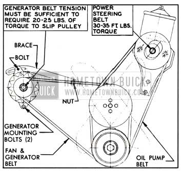
1957 Buick Belt Adjustments
The generator must be moved sidewise to adjust the 1957 Buick fan belt. After the generator brace and mounting bolts are securely tightened, the fan belt tension should be checked by torque wrench at the generator pulley nut. A properly tensioned new belt will require 25 to 30 ft. lbs. torque to slip the generator pulley. A used belt will require 20 to 25 ft. lbs.
If the power steering oil pump belt is removed it should be adjusted to torque specified in paragraph 8-12 (c).
If the Air Conditioner compressor belt is removed it should be adjusted to torque specified in par. 11-8.
2-22 1957 BUICK RADIATOR THERMOSTAT INSPECTION AND TEST
A sticking radiator thermostat will prevent the cooling system from functioning properly. If the thermostat sticks in the open position, the 1957 Buick engine will warm up very slowly. If the thermostat sticks in the closed position, overheating will result.
The thermostat may be removed for inspection and test by partially draining the cooling system and disconnecting the water outlet and hose from the water manifold, in which the thermostat is located.
If the 1957 Buick thermostat valve does not fully close when cold, replace the thermostat. If the valve will fully close when cold, test the thermostat for correct opening temperature by immersing the unit and a thermometer in a container of water over a heater. While heating the water do not rest either the thermometer or thermostat on bottom of container as this will cause them to be at higher temperature than the water. Agitate the water to insure uniform temperature of water, thermostat and thermometer.
The standard thermostat (160°) valve should start to open at a temperature of 157° F. to 162° F., and should be fully open at a temperature not in excess of 182° F. On the high temperature (180°) thermostat which may be installed to improve car heater performance, the valve should start to open at a temperature of 177° F. to 182° F., and should be fully open at a temperature not in excess of 202° F. If thermostat does not operate at specified temperatures it should be replaced as it cannot be adjusted.
2-23 1957 BUICK WATER PUMP REPAIRS
Removal and Disassembly
- Drain 1957 Buick engine cooling system, being sure to drain into a clean container if anti-freeze solution is to be saved.
- Loosen fan belt, then remove fan blade, spacer, and pulley from hub on water pump shaft. Remove – belt.
- Disconnect hose from water pump inlet, then remove pump cover assembly and gasket from timing chain cover.
- Remove impeller from pump shaft, using a suitable puller. A puller with two hooks is preferred, however, a puller with three hooks may be used.
- Remove carbon washer, rubber bellows and spring from the brass sleeve that is pressed into pump housing. It is not necessary to remove the brass sleeve if it is in good condition. If sleeve is doubtful, however, remove by driving it out with a punch inserted through vent hole in pump body.
- Thoroughly clean the pump cover to remove rust, old gasket, etc. Do not soak in cleaning solvent as this may leak into pump shaft bearing and destroy the lubricant.
- Check pump shaft bearing for end play, or roughness in operation. If bearing is not in serviceable condition, press the fan hub off the shaft then press bearing out toward FRONT of pump cover. See figure 2-38.
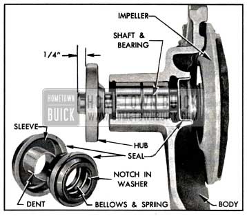
1957 Buick Water Pump Parts
Assembly and Installation
- If old pump shaft bearing was removed, press a new bearing in against the shoulder in pump cover with the long end first.
- Use care to start the fan hub squarely on front end of bearing shaft and press it into position 1/4″ from end of shaft. See figure 2-38.
- If the old brass seal sleeve was removed from pump body, carefully press the sleeve of new seal assembly into place, using a thick walled tube of proper inside and outside diameters to bear fully against flange of sleeve. It is not necessary to remove the other seal parts from sleeve.
NOTE: The seal with external spring used prior to 1958 may be used alternately in production or service.
If old sleeve was not removed, separate the new seal sleeve from seal bellows by soaking in hot water to soften the cement used to hold seal parts together for ease of handling.
Install the carbon washer, bellows and spring assembly in the old sleeve in pump body, being careful to engage the two notches in washer with the driving dents in brass sleeve. See figure 2-38.
- Coat the face of carbon washer and impeller hub with rust preventative or Seco Oil, then support pump assembly on the fan end of shaft and press the impeller on inner end of shaft until rear face of impeller is flush with end of shaft.
- Make sure that gasket surfaces on pump and timing chain covers are clean then install pump cover assembly with a new gasket. Pump cover bolts with lockwashers must be tightened uniformly.
- Connect radiator hose to pump inlet then fill cooling system and check for water leaks at pump and hose joints.
- Install fan pulley, spacer and fan blade and tighten attaching bolts securely. Install fan belt and adjust for proper tension (par. 2-21).
2-24 1957 BUICK OIL AND VACUUM REPAIRS
When an oil pump is removed for repairs the following procedure must be used to inspect parts and assemble pump in order to insure adequate oil pressure when the work is completed.
- Remove vacuum pump housing with end cover, then remove the oil pump shaft and gear, and idler gear from the pump body. See figure 2-39.
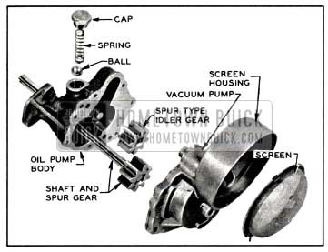
1957 Buick Oil Pump and Screen
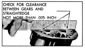
1957 Buick Checking Clearance of Gears at Cove
If pump shaft tends to bind when bolts are evenly tightened, it may be freed up by rapping pump body lightly with a rawhide mallet. Pump shaft must be free of bind when bolts are securely tightened.
Vacuum pumps are serviced only as complete assemblies. If severe damage to vacuum pump is encountered, it is recommended that the oil pump idler gear and driving key be inspected before replacing vacuum pump.
Leave A Comment
You must be logged in to post a comment.