SECTION 9-D 1957 BUICK POWER BRAKES
9-15 DESCRIPTION OF 1957 BUICK POWER BRAKE MECHANISM
Wheel brake assemblies used in a 1957 Buick power brake system are identical with those used in a regular brake system. The 1957 Buick power brake unit provides lighter pedal pressures due to vacuum assist. These lighter pedal pressures are obtained with reduced pedal travel making it possible to have the brake pedal height more nearly the same as the accelerator pedal height.
The brake pedal is suspended from a bolt between two mounting brackets. A: the brake is applied, a pedal lever extending upward operates a link rearward. This link in turn transmits motion to a lever on an idler, causing the idler to rotate. This rotation causes a second idler lever to push forward on the brake cylinder push rod clevis and push rod. The overall mechanical advantage in the 1957 Buick power brake linkage is approximately 1 1/2 to 1. See Figure 9-13.
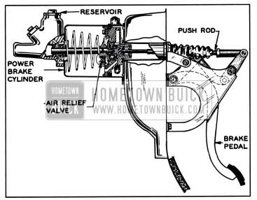
1957 Buick Power Brake Installation
All pivot points in the brake linkage have nylon bearings which are lubricated when installed but do not require periodic lubrication. Because there is no pedal stop, the pedal will be stopped in the “off” position by contact of the push rod with the stop plate in the power cylinder. The only linkage adjustment possible is the pedal height adjustment (par. 9-16).
The 1957 Buick power brake assembly is a self-contained vacuum and hydraulic unit which utilizes the difference between intake manifold vacuum and atmospheric pressure to reduce brake pedal effort. Both Bendix and Moraine power brake units are used on an optional basis. Internally, the Bendix and Moraine units differ in construction, but both units have the same external dimensions and may be used interchangeably. Both units have an air suspended power cylinder and a displacement type hydraulic cylinder.
The 1957 Buick power brake cylinder is connected to the intake manifold through pipes and flexible connections. A vacuum reserve tank of approximately 360 cubic inches capacity is connected into the vacuum line near the power brake cylinder to insure quick and smooth response of the brake cylinder on all power brake applications. A check valve installed in the vacuum line closes to maintain existing vacuum at the power cylinder and in the reserve tank whenever manifold vacuum falls below that in the brake system.
When the engine is stopped and check valve is closed, the tank provides sufficient reserve vacuum for four to seven normal power brake applications. When reserve vacuum does not exist, the brakes can be applied manually in the same manner as the regular brakes, except that somewhat more effort is required.
9-16 REMOVAL, INSTALLATION, ADJUSTING, TESTING OF 1957 BUICK POWER BRAKE UNITS
The same procedure is used for removing, installing, adjusting, or testing either the Moraine or the Bendix power brake unit. Operation, disassembly and assembly are different, however, and are covered in separate paragraphs as shown in the index for section 9-D.
Removal of 1957 Buick Power Brake Unit
- Disconnect battery ground strap.
- Remove clevis pin from push rod clevis. See figure 9-13.
- Lift brake pedal to pull linkage out of the way, then remove large nut holding brake unit to cowl using Wrench 6618.
- Disconnect stop light wire connector from switch.
- Disconnect brake pipe from hydraulic cylinder and tape end of pipe to prevent entrance of dirt. Disconnect vacuum hoses from vacuum tee.
- Remove bolts holding unit to ventilation air duct and remove power brake unit from car.
- Remove filler cap and turn unit so that any brake fluid will drain out. Pump push rod by hand for full interior drainage. Discard old fluid. Install filler cap and cover hydraulic cylinder outlet with tape to exclude dirt. Clean all loose dirt from outside of unit before disassembling.
Installation of 1957 Buick Power Brake Unit
- Position 1957 Buick power brake unit in ventilation air duct and install bolts to hold unit to air duct.
- Connect brake pipe to hydraulic cylinder. Connect vacuum hoses to vacuum tee.
- Connect stop light wire connector to switch.
- Loosen brake reinforcing bracket bolt and nut. Lift brake pedal to pull linkage out of the way, then install and tighten large nut using Wrench 6618. After large nut is tight, tighten reinforcing bracket bolt and nut.
- Install spring washer, clevis pin, and cotter key in push rod clevis.
- Check brake pedal for correct height as described below (subpar. c). Adjust pedal height if necessary.
- Reconnect battery ground strap.
- Bleed hydraulic system in same manner as standard brake system. After bleeding bring fluid level to 1/4 inch below lowest point of bottom thread in filler opening. NOTE: When pressure bleeding equipment is not available, do not use any vacuum assist. The engine should not be running and the vacuum reserve should be used up by repeatedly applying the brake before starting the bleeding procedure.
Checking and Adjusting 1957 Buick Brake Pedal Height
Correct pedal height is important to insure adequate pedal travel and to make sure that the pedal is in the proper position to get the best linkage action.
- Make certain that brake pedal returns completely when released slowly. If pedal does not return freely, check linkage for binding and check condition of pedal return spring.
- Measure from left top side of pedal pad perpendicular to toe pan using a foot ruler. Pedal height with ruler pressed firmly against floor mat should be 5 1/2 inches plus or minus 1/4 inch. See figure 9-7.
- If pedal height is incorrect, loosen push rod lock nut.
- Turn push rod as necessary to adjust pedal height to 5 1/2 inches.
- Hold push rod and tighten lock nut. Recheck pedal height.
- Start engine and depress brake pedal firmly. If pedal travels to within 1 inch of toeboard and has a hard feel, brake shoes require adjustment or relining. However, if pedal has a spongy feel, brake system needs bleeding.
Testing 1957 Buick Power Brake Unit
- Vacuum Assist. With engine stopped, apply brakes several times until all vacuum reserve in system is used up. Then depress brake pedal and start engine while holding a light pedal pressure. If vacuum system is operating properly, pedal will tend to fall away from under the foot, and less foot pressure will be required to hold pedal in same position. If no action is felt, vacuum system is not functioning.
- Hydraulic Leak. Apply a heavy foot pressure on brake pedal with engine running. Hold this pressure at least 15 seconds and observe brake pedal. If pedal goes down gradually, check first for a leak in system outside of 1957 Buick power brake unit. When possibility of an external leak is eliminated, leak is in hydraulic cylinder of power brake unit.
- Vacuum Leak. Allow engine to idle a minute to build-up vacuum reserve. Shut off engine and wait several minutes at least (system should hold vacuum for 12 hours) before trying brake action. If brake is not vacuum assisted for at least 5 slow applications there is a leak in the vacuum system. Always check for an external leak before blaming leak on 1957 Buick power brake unit.
- Road Test. Apply brakes several times at about 20 m.p.h. to determine if a light pedal pressure stops the car evenly and quickly. Notice pedal feel as compared to other cars of the same model.
9-17 MORAINE POWER BRAKE UNIT
Construction of Moraine Power Brake Unit
The 1957 Buick power brake cylinder is the “air suspended” type, meaning that atmospheric pressure is present on both sides of the power piston in the unapplied stage.
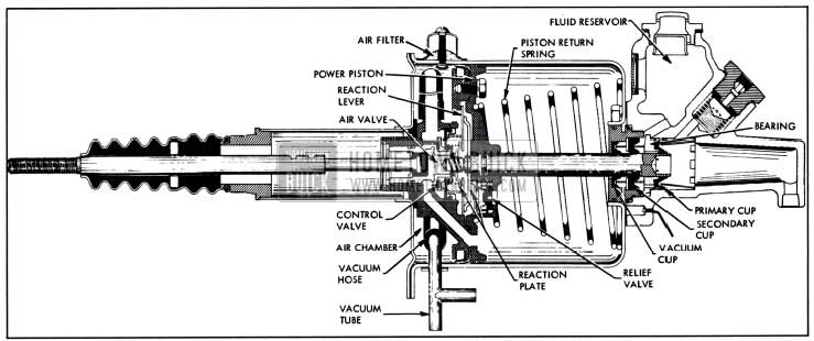
1957 Buick Moraine Power Brake Unit-Released Position
As shown in figure 9-14, a cover closes the forward end of the cylinder housing to form a large chamber in which the power piston and related parts operate. The section on the cover side of the piston is called the air chamber since it is open to atmospheric pressure at all times. The section on the opposite side of the piston is called the vacuum chamber since it is subjected to manifold vacuum during power application of brakes. All air entering the cylinder housing passes through an air cleaner.
The rim of power piston carries a spring expanded leather cup and a felt lubricating wick to seal against passage of air. A flexible rubber hose connecting the piston with a vacuum tee on the side of cylinder housing permits the piston to move back and forth while connected to manifold vacuum. Air is exhausted out of the vacuum chamber through passages in the piston and the vacuum hose when the control valve is set for power application.
The related parts which operate in the cylinder housing with the power piston form an assembly composed of the air valve, floating control valve, hydraulic piston, and the reaction mechanism. Pedal pressure through a push rod starts the power piston assembly moving when applying the brakes; a single heavy return spring returns the power piston when releasing the brakes.
The hydraulic piston is a solid steel plunger which extends into the hydraulic cylinder through a rubber vacuum cup and rubber secondary and primary cups. To prevent vacuum from drawing brake fluid out of hydraulic cylinder in case of cup leakage, the space between the vacuum cup and the secondary cup is vented to atmosphere through a hole which is kept open by a loose wire.
Movement of the piston into the fluid filled cylinder displaces a corresponding volume of the fluid, which is forced out into the brake pipes and wheel cylinders. Compensating ports in the counterbored end of the piston permit return of surplus fluid to reservoir when brakes are released. The check valve and spring in the hydraulic cylinder maintains a static residual pressure in brake pipes and wheel cylinders.
Operation of 1957 Buick Moraine Power Brake Unit
Description of 1957 Buick power brake cylinder operation will cover (1) Released Position (2) Applying (3) Reaction Pressure (4) Holding (5) Releasing ( 6) Manual Applying.
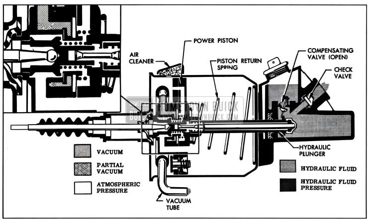
- Released Position. See figure 9-14. The pedal return spring and the valve return spring hold the push rod and attached air valve so that the air valve is held clear of the floating control valve. At the same time, the valve diaphragm spring holds the floating control valve against its seat on the power piston, thereby closing the passage connected to manifold vacuum.
Atmospheric pressure enters through the air cleaner into the air chamber, flows through the space between the air valve and the floating control valve, then flows through a passage in the power piston into the vacuum chamber. With the vacuum passage closed and the vacuum chamber open to outside air, the power piston is balanced by atmospheric pressure on both sides and is held against the housing cover by the return spring.
The compensating ports in counterbored end of hydraulic piston are rearward of the primary cup, permitting flow of brake fluid between the reservoir and hydraulic cylinder as required. The check valve is seated to maintain static pressure in the brake pipes and wheel cylinders. - See figure 9-15.
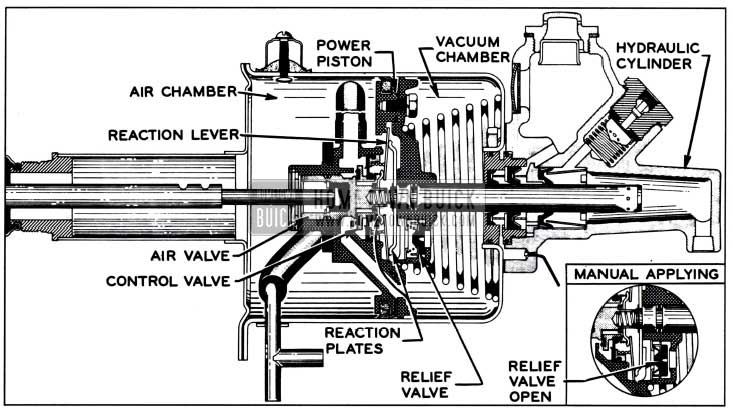
1957 Buick Power Brake Applying
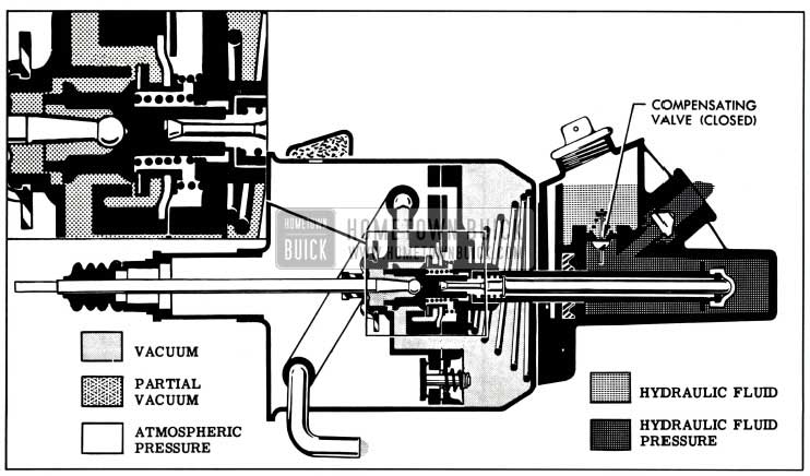
As the brake pedal is depressed the push rod moves the air valve until its annular seat contacts the floating control valve, at which point atmospheric pressure is sealed off from the vacuum chamber.
Further movement of the air valve pushes the floating control valve away from its seat on the power piston, thus connecting the vacuum chamber to manifold vacuum through a passage in power piston and the attached vacuum hose. As air is exhausted out of the vacuum chamber, atmospheric pressure in the air chamber moves the power piston forward toward the hydraulic cylinder. The valve and hydraulic piston move forward as a unit with the power piston.
As the hydraulic piston is forced into the hydraulic cylinder, escape of fluid into the reservoir is cut off when the piston compensating ports pass through the primary cup, and the fluid displaced by the piston is then forced out into the brake pipes and wheel cylinders to apply the brake shoes. At the same time, a reaction pressure is transmitted back to the brake pedal to give the driver an indication or “feel” of the pressure being applied to the brake shoes.
In this manner approximately 40 % of the load on the hydraulic piston is transferred through the air valve and push rod to the brake pedal to oppose the foot pressure applied by the driver. This reaction pressure gives the driver a definite indication of “feel” of the pressure being applied to the brake shoes so that he has positive control over the braking operation at all stages.
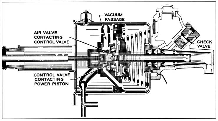
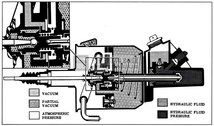
1957 Buick Power Brake Holding
At this point, the air valve is also in contact with the control valve so that the passages to the vacuum chamber are sealed off from atmospheric pressure as well as vacuum; therefore the power piston is held stationary or poised, ready to move in either direction as dictated by brake pedal movement.
As the hydraulic piston moves out of the hydraulic cylinder the fluid from the wheel cylinders flows back into the hydraulic cylinder through the check valve. When the compensating ports in the piston pass forward through the primary cup, any surplus fluid in the hydraulic system can return to the reservoir. The check valve spring presses the check valve against its seat with sufficient pressure to maintain some static pressure in the brake pipes and wheel cylinders.
As the hydraulic piston moves it carries the complete power piston assembly along with it.
Under a sudden manual brake application, the rapid movement of the power piston tends to compress air ahead of it, resulting in a “dashpot” effect. To eliminate this possibility, a spring-loaded relief valve in the power piston allows air to flow very easily from the forward side of the power piston to the rear side.
If the engine is started while the brakes are being manually applied, manifold vacuum will exhaust air from the vacuum chamber through the wide open vacuum port at the control valve, and the power piston will move forward. This will make the pedal “fall-away” slightly from under the foot and less foot pressure will be required to hold the pedal in the applied position.
9-18 DISASSEMBLY, INSPECTION, ASSEMBLY OF 1957 BUICK MORAINE POWER BRAKE UNIT
NOTE: Refer to figures 9-14 and 9-15 for identification of parts not shown in figures next to overhaul steps.
Disassembly of Power Unit
- Measure distance push rod projects through clevis. Record this dimension so that clevis can be reinstalled in same position. Then remove clevis.
- Mount 1957 Buick power brake unit in vise with hydraulic cylinder down, being careful not to damage the loose vent pin in flange of hydraulic cylinder. Tighten vise only enough to hold cylinder firmly; excessive tightening will distort or crack cylinder.
- Remove push rod boot from housing cover tube and from push rod. Remove felt air silencer from push rod boot. Take out air cleaner screw and remove air cleaner cover and filter.
- Take out vacuum tube screws. Remove housing end cover screws, cover and gasket.
While holding power piston down, disconnect vacuum hose from vacuum tube and remove tube and gasket from housing. See figure 9-17.
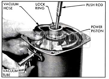
1957 Buick Removing Vacuum Tube
Slowly release power piston to control pressure of piston return spring as piston and attached parts emerge from housing. Make sure that lip of leather piston cup does not catch in holes in housing.
- Pull vacuum hose off power piston, if hose is defective.

1957 Buick Power Piston Assembly-Exploded
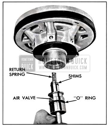
1957 Buick Removing or Installing Air Valve Assembly
Truarc Pliers J-5403 to disengage snap ring. Then pull out push rod, bumper and washer.
- Remove sponge rubber piston stop bumper.
- Remove four cap screws holding piston guide to power piston while holding assembly together against inner spring load. With piston flat, carefully lift piston guide straight up to avoid disturbing loose parts under piston guide. Lift off loose „O“ ring.
- Push hydraulic piston out through piston guide and remove „O“ ring from hydraulic piston.
- If reaction plate or hydraulic piston is defective, separate them using No.2 Truarc Pliers J-4880 to remove snap ring.
- Inspect relief valve which is staked in place in piston guide. Remove relief valve if it is defective. See figure 9-20.
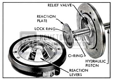
1957 Buick Reaction Levers and Related Parts
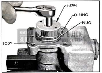
1957 Buick Removing Cylinder Plug
Cleaning, Inspection, Replacement of Parts
As an aid in determining the cause of improper power brake operation, wipe fluid from all rubber parts, then carefully examine these parts for nicks, cuts or other damage. After examination discard all these parts.
Thoroughly clean the remaining parts in diacetone alcohol or clean brake fluid.
CAUTION: Do not use anti-freeze alcohol, gasoline, kerosene, or any other cleaning fluid that might contain even a trace of mineral oil, as this could cause serious damage to all rubber parts in the brake system.
Carefully examine the cleaned parts for nicks, burrs, stripped threads, damage or excessive wear. Replace damaged or excessively worn parts or housings. If inside of vacuum power cylinder is rusted or corroded, polish with steel wool or fine emery cloth. Replace when scored.
Make certain that the small compensating ports in end of hydraulic piston are clear. If these ports are plugged, clean them thoroughly and flush the hydraulic system to remove all dirt.
If the outer surface of the air valve or the hydraulic piston show evidence of abrasion, polish out light scores with crocus cloth or very fine polishing paper, then wash and dry thoroughly.
If any parts indicate that heavy abrasive action has resulted from severe contamination of the brake fluid, replace damaged parts and be sure to thoroughly flush the reservoir and wheel cylinder lines.
Make sure that the loose pin is properly retained in vent hole in flange of hydraulic cylinder body, and that vent hole is clear.
The 1957 Buick Power Brake Cylinder Overhaul Kit (Group 4.898) contains all necessary replacement parts for the 1957 Buick power brake cylinder. When reassembling the brake cylinder use all the new parts in the kit regardless of whether the old parts appear fit for use. Discard all old rubber parts. In addition, replace any other parts which inspection indicates to be unfit for use.
Lubricate all hydraulic master cylinder parts with clean brake fluid. Lubricate vacuum power piston parts where lubrication is specified with Dynaflow oil. Do not lubricate parts until just before installation.
Assembly of 1957 Buick Moraine Power Brake Unit
- Clamp hydraulic master cylinder body in vise with threaded outlet hole straight up. Into this hole, place check valve spring. Place new check valve, concave side out, on spring. Place new gasket and stretch new seat washer onto head nut. Set head nut squarely against check valve and press against spring to hold check valve in position while head nut is started in threads. Run down finger tight, back off one or two turns to allow check valve to center, then torque to 85-90 ft. lbs.
- Reposition hydraulic cylinder in vise with large bore straight up. Wipe bore and threads with a thin coat of clean brake fluid.
- Into bore, set conical primary cup retainer with notched end in first. Dip primary cup in clean brake fluid and install lip side first over retainer. Center lip of cup must fit in hole. Set primary cup ring of thin blued steel on flat of primary cup. With notched face out, place piston bearing on primary cup ring with hub of bearing fitting into opening in cup, then press home to solid seat. Now set dark secondary cup retainer to center on bearing and position expander on retainer with notched side in.
- On master cylinder plug, install two „O“ rings on first and third grooves of plug. Do not place an „O“ ring in center groove which has four small vent holes. Install vacuum seal in bottom of bore in plug flat side down. Position light colored retainer on seal, then install fiat support on shoulder in bore. Place secondary cup fiat side down against support.
- Moisten „O“ rings on plug with clean brake fluid and screw plug assembly into hydraulic body, checking that secondary cup retainer and expander are centered. Use Wrench J-5794 to tighten plug to 20-30 ft. lbs.
- If vent pin was removed, install in vent hole and bend to about 45° angle to hold in place. Set assembled hydraulic cylinder aside to protect from dirt or damage.
- To assemble floating valve assembly, stretch new diaphragm to fit in groove on diaphragm retainer. See figure 9-22.
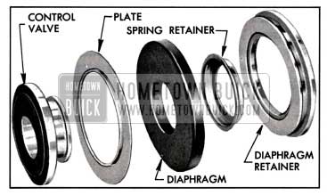
1957 Buick Floating Valve Assembly-Exploded
Hold fiat side of plate against fiat side of diaphragm while pressing floating control valve into center hole of diaphragm. Use thumbs to stretch diaphragm over hub of floating control valve, then press spring retainer over valve hub and diaphragm lip. Lubricate O.D. of floating valve with Dynaflow oil and press into place in power piston with rubber face of floating control valve facing in.
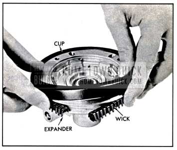
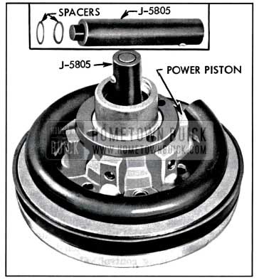
1957 Buick Installing Leather Piston Cup
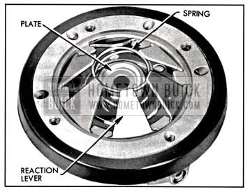
1957 Buick Installing Reaction Levers
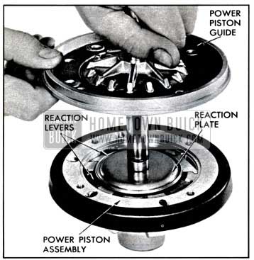
1957 Buick Installing Piston Guide
Hold pressure while sliding piston guide down over hydraulic piston for installation of screws. Note that reaction levers must hold position, piston guide must clamp leather cup while expander and wick hold position under cup, and all holes must align-all at the same time. When correct, install screws and torque to 5-6 ft. lbs. NOTE: To assure that reaction levers are properly seated, check to see that master cylinder piston has a slight movement in power piston assembly.
1957 Buick Checking Spacer Thickness
(The body of the gauge sets against the smaller reaction plate while the pin of the gauge extends through to contact the master cylinder piston.) Now turn whole assembly over to bring gauge on top and observe gauge pin in gauge body as shown in figure 9-26. CAUTION: Hydraulic master cylinder piston must be at lowest limit for correct use of gauge. Do not hold assembly by hydraulic piston or allow hydraulic piston to contact bench.
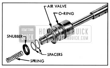
1957 Buick Air Valve and Related Parts
1957 Buick Positioning Piston In Housing
Push piston assembly into housing past vacuum tube hole. Place gasket against vacuum tube flange, then insert vacuum tube through hole and slide into vacuum hose. Hold piston assembly in until vacuum tube attaching screws are tightened, then release piston slowly against tube.
9-19 1957 BUICK BENDIX POWER BRAKE UNIT
Construction of 1957 Buick Bendix Power Brake Unit
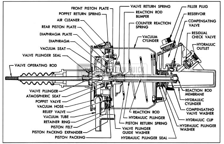
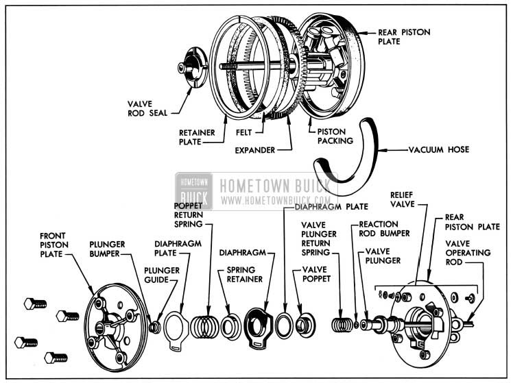
The 1957 Buick Bendix power brake unit consists of two basic sections combined into a single unit; these are the vacuum power cylinder and the hydraulic master cylinder. The vacuum power cylinder consists of a cylinder, a power piston and valve assembly, a piston return spring, a valve operating rod and a hydraulic plunger assembly. The hydraulic master cylinder consists of a hydraulic cylinder, a reservoir, a residual check valve, a compensating valve, and the forward end of the hydraulic plunger with its cup and seal. See figure 9-29.
1957 Buick Bendix Power Brake Unit
The power piston and the components which make up the valve assembly are connected to the brake pedal through the valve operating rod. The valve operating rod is connected to the valve plunger which operates within the power piston. The valve return spring is incorporated to return the valve plunger and the valve operating rod to the released position when the brakes are released. A separate poppet type air relief valve is built into the power piston; this valve functions only when a brake application is made without vacuum assist.
The valve portion of the power piston consists of a poppet valve, an atmospheric port and a vacuum port. The atmospheric port seat is located on the valve plunger while the vacuum port seat is located in the rear half of the power piston.
The poppet valve is assembled into a flexible diaphragm in the power piston. A diaphragm plate is used in conjunction with the diaphragm to limit the effective area of the diaphragm. When the power cylinder is in the released position, the poppet return spring overcomes the force present on the poppet as a result of the atmospheric pressure on the left side of the poppet and the vacuum on the right side of the poppet so that the return spring holds the poppet on the vacuum seat. A valve plunger seal is used to seal the opening between the rear piston plate and the valve operating rod.
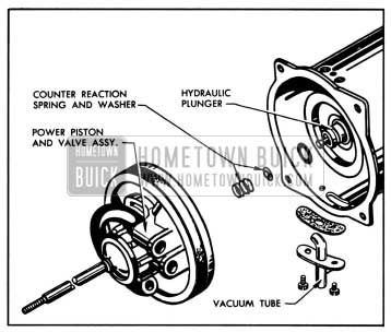
The power piston is in contact with the hydraulic plunger at all times and thereby transmits the force of the piston to the fluid in the hydraulic cylinder. A reaction rod which is a part of the hydraulic plunger assembly operates within the hydraulic plunger to transmit a “reaction force” back through the rod against the valve plunger. A counter reaction spring located between the power piston and reaction rod, permits initial application of power before sufficient hydraulic pressure is developed within the hydraulic cylinder to react through the reaction rod membrane at the end of the hydraulic plunger and the reaction rod.
The hydraulic cylinder with the fluid reservoir is attached to the end of the vacuum cylinder. The hydraulic cylinder is sealed off from the vacuum cylinder at the hydraulic plunger by a leather wiper seal and a rubber cup. A compensating valve is placed between the hydraulic cylinder and the fluid reservoir. This valve is of the tilting type and is closed at all times except when the hydraulic plunger is in its fully released position. A residual check valve which is located at the output end of the hydraulic cylinder traps a slight pressure in the hydraulic lines and wheel cylinders when the brakes are released as in the conventional brake system. This prevents the entrance of air into the hydraulic brake lines upon release of the brakes.
Operation of 1957 Buick Bendix Power Brake Unit
Description of power brake operation will cover (1) Released Position (2) Applying (3) Reaction Pressure ( 4) Holding ( 5) Releasing ( 6) Manual Applying.
- Released Position. See figure 9-30.
1957 Buick Power Brakes Released Position
When the engine is running and the brakes are released, vacuum from the engine intake manifold is transmitted through the vacuum check valve to the 1957 Buick power brake vacuum tube and to the vacuum reservoir. Vacuum is transmitted into the 1957 Buick power brake unit through an internal vacuum hose which is attached to the power piston at the rear side. Atmosphere is always present on the left side of the power piston through the air cleaner. In the released position, as shown in figure 9-30, the driver’s foot pressure is removed from the valve operating rod. This allows the valve operating rod and valve plunger to be held to the rear in the power piston by the valve return spring, thus opening the atmospheric port and closing the vacuum port. With atmosphere present on both sides of the power piston, the piston return spring (attached to the hydraulic plunger) holds the hydraulic plunger and power piston assembly in the released position.
When the power piston and valve operating rod are in their released positions, the various parts of the hydraulic master cylinder are also in their released positions. The compensating valve is tilted by the washer at the end of the hydraulic plunger permitting fluid flow from the reservoir to the hydraulic cylinder. The expansion, contraction or leakage of fluid is thereby compensated for as in a conventional brake system. The residual pressure check valve maintains fluid under slight pressure in the lines and wheel cylinders to prevent the entrance of air into the hydraulic system.
1957 Buick Bendix Power Brakes Applying
As the brake pedal is depressed, the valve operating rod moves the valve plunger and closes the atmospheric port. After the atmospheric port is closed against the poppet, further movement of the valve operating rod and plunger moves the poppet valve, compressing the poppet return spring and opening the vacuum port. With the vacuum port open, vacuum is admitted through the piston passages to the forward side of the power piston. With partial vacuum on the forward side of the power piston and atmosphere on the rear side of the piston, the differential in pressure creates a force which moves the power piston forward, moving the hydraulic plunger with it. Initial movement of the plunger allows the compensating valve to seat and trap fluid in the hydraulic cylinder. Fluid under pressure is then forced through the residual pressure check valve and brake lines to the wheel cylinders.
1957 Buick Bendix Power Brakes Holding
When the force applied by the driver remains constant, the valve is allowed to remain in its holding position. In the holding position both the vacuum and the atmospheric ports of the poppet valve are closed. However, any increase in the force applied by the driver to the valve operating rod and plunger will cause the vacuum port to reopen, admitting more vacuum to the forward side of the power piston. This will cause the power piston to move farther forward until it again “catches-up” with the valve plunger and poppet. The vacuum port will then close and the valve is again in the holding position.
Because of the tendency of the air in the cylinder on the forward side of the power piston to compress when the brake is manually applied, there is a relief valve in the power piston to allow this air to escape more rapidly. This relief valve eliminates any “dash pot” effect in the power cylinder when it is operated without vacuum.
9-20 DISASSEMBLY, INSPECTION, ASSEMBLY OF 1957 BUICK BENDIX POWER BRAKE UNIT
NOTE: Refer to figures 9-29 and 9-31 for identification of parts not shown in figures next to overhaul steps.
Disassembly of Power Unit
- Measure distance push rod projects through clevis. Record this dimension so that clevis can be reinstalled in same position. Then remove clevis.
- Clamp unit in vise with push rod straight up and remove rubber dust boot from tube on end plate and from push rod. Bend out tabs on end plate. Remove end plate and gasket.
- Slide vacuum hose off vacuum tube. Remove vacuum tube attaching screws, vacuum tube and gasket.
- Remove air cleaner attaching screw and screw gasket. Remove air cleaner shell, hair, and rubber gasket.
- Remove burrs from inside of vacuum cylinder at air cleaner and vacuum tube attaching screw holes. Then pull out power piston and valve assembly from cylinder. See figure 9-33.
1957 Buick Removing Power Piston Assembly
1957 Buick Bendix Power Piston Assembly-Exploded
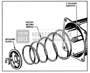
1957 Buick Removing Piston Return Spring
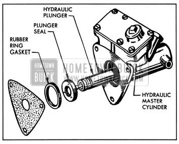
1957 Buick Removing Vacuum Cylinder from Hydraulic Cylinder
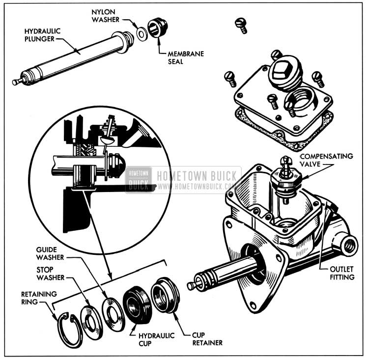
1957 Buick Hydraulic Cylinder Assembly-Exploded
1957 Buick Compensating Valve Assembly
Cleaning, Inspection, Replacement of Parts
The cleaning and inspection procedure in general is the same for the Bendix as it is for the 1957 Buick Moraine power brake unit. See Paragraph 9-18 (b).
Assembly of 1957 Buick Bendix Power Brake Unit
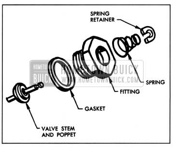
- To assemble compensating valve, clamp fitting in vise, then insert valve stem and poppet through hole in fitting from threaded end. Assemble large diameter end of spring over stem, hold valve poppet on seat, compress spring and assemble new spring retainer washer in groove of valve stem. See figure 9-38. Squeeze ends of washer together with pliers. Assemble new gasket over threads of fitting. Do not install compensating valve assembly in hydraulic cylinder at this time.
- To assemble residual check valve, assemble new gasket over threads of hydraulic outlet fitting. Insert cone end of check valve cup and retainer in fitting. Place check valve spring in recess of retainer. Hold hydraulic master cylinder so that outlet hole is straight down and thread outlet fitting and check valve assembly into hydraulic cylinder hand tight. See figure 9-39.
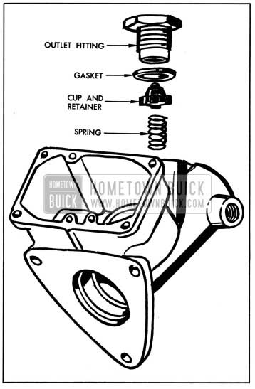
1957 Buick Removing or Installing Residual Check Valve
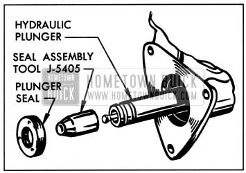
1957 Buick Installing Plunger Seal
Leave A Comment
You must be logged in to post a comment.