3-1 AIR CLEANER AND INTAKE SILENCER
The low restriction concentric type air cleaner used on the 1955 40 Series will continue to be used in 1956.
An improved air cleaner will be used on the 60-50-70 Series. Due to the engine’s increased volumetric efficiency, the element has been redesigned to prevent the possibility of reservoir oil from being pulled into the carburetor. The low restriction and free breathing characteristics are maintained. See Figure 3-1.
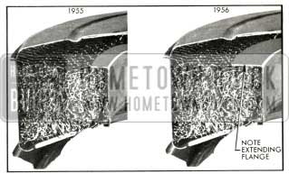
1956 Buick Cross Section Comparison of 1955 and 1956 Air Cleaners
3-2 CARBURETOR THROTTLE LINKAGE
A revised version of the 1955 throttle linkage is used on 1956 Dynaflow equipped cars. The throttle linkage again serves a dual purpose-operating the carburetor throttle valves from closed to full throttle, and regulating the transmission stator valve in either Cruise or Performance position. The overtravel link (stretch link) has been removed and replaced by a solid rod. The linkage is designed to reach the stator high angle position and full throttle simultaneously. The main part of the pedal travel operates the throttle only, while the last one-half inch of travel operates the stator piston control valve which shifts the stator blade to the high angle or Performance position. See Figure 3-2.

1956 Buick Throttle Linkage
A standard accelerator pedal has been adopted for all models, the relative height between the power brake pedal and the accelerator pedal remaining the same as in 1955.
Intake Manifolds and Heat Control
New intake manifolds are used on all engines for 1956. In order to improve warm-up operation, the heat passages have been revised in that the amount of heat on the “T” section has been reduced and the heat has been added to the floor of the riser. Also, exhaust heat has been applied by way of the intake manifold passages to the base of carburetor throttle body to reduce carburetor icing. These intake manifolds are identical with those used in late 1955 production. See Figure 3-3.
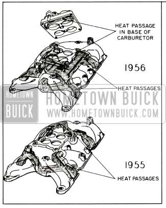
1956 Buick Comparison 1955 and 1956 Intake Manifolds
Exhaust Systems
Buick engines for 1956 will be equipped with single exhaust or dual exhaust systems. A dual exhaust system will be standard on the 70 Series and optional on the Series 40, 50 and 60.
The Series 40-50-60 will have a redesigned single exhaust system as standard equipment. See Figure 3-4.
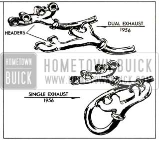
1956 Buick New Dual and Single Exhaust Systems
The exhaust manifolds, referred to as the double “Y” type, provide a separation of 270 degrees between the exhaust cycles of the cylinders exhausting into any one manifold branch which virtually eliminates overlap within a given manifold branch. This is accomplished by having two separate branches in each manifold joining for a common outlet at a point above the flange.
The right manifold is common to both the new single and the new dual exhaust systems. A carburetor choke heat stove is incorporated in this manifold since it is common to both systems.
The new left manifold for the single system is divided with a branch at each end and joining in the middle at a point just above the flange.
The new left hand manifold for the dual exhaust system is identical to that of the new single system with but one exception. The branches join at a point near the rear of the engine _providing an advantageous location for the flange connecting to the left exhaust pipe.
A worthwhile power gain is obtained using either of the above combinations with the greater gain obtained using the dual exhaust system.
Mufflers
The single exhaust system will employ the same muffler used in 1955 except that the new type ball joint connectors will be an added feature. See Figure 3-5.

1956 Buick Cross Sectional Views of Mufflers
New three tube reverse flow mufflers will be used with the dual exhaust system. The three tube reverse flow feature provides quiet operation with minimum power loss. All mufflers are heavily plated with aluminum or zinc for improved life. The dual exhaust mufflers can be used on either the left or right sides; however, they are not interchangeable with the single exhaust muffler. See Figures 3-6 and 3-7.
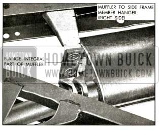
1956 Buick Front of Muffler and Hanger

1956 Buick Rear of Muffler and Hanger
Tail Pipes
The dual tailpipes are of heavy wall design and are aluminum coated for added life. Also, they have been located for added ground clearance by passing through the bottom of the bumper and mounted so that no restrictive effect is placed in the exhaust stream.
Ball Joint Connectors
The new ball joint connectors improve alignment and eliminate binds with a resultant reduction of interference which could cause noise and vibrations. Any individual piece of the exhaust system can be removed without loosening or detaching the rest of the system. No gaskets are necessary in the entire exhaust system. See Figure 3-8.
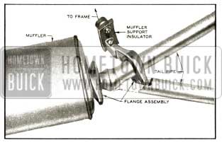
1956 Buick Ball Joint Connector
3-4 FUEL PUMP
The 1956 fuel pump will be the same as in 1955 from the standpoint of operation. The pulsator cover has been redesigned and the pump body will be of magnesium alloy composition rather than zinc alloy as in the past. The rocker arm will be a stamping rather than a forging as in the past. The new pump will weigh one third less than previous models.
3-5 CARBURETORS
The following carburetors which are similar to those used in late 1955 will be used in conjunction with 1956 Buick engines. Specifications for the 1956 model carburetors will be covered in future BPS Bulletins.
Two 2-barrel carburetors will be used on the 40 Series Dynaflow engine which are as follows: Carter 2400 S Model WGD, and Stromberg 7-105 Model WW. Also, a special 2-Barrel Carter 2378S Model WGD will be used on the 40 Series synchromesh engine.
Two 4-barrel carburetors will be used in conjunction with 50-60-70 Series engines which are as follows: Rochester, Part No. 7009200 Model 4GC, and Carter 2347 Model WCFB.
Leave A Comment
You must be logged in to post a comment.