ENGINE GENERAL SPECIFICATIONS
Except for changes described in this group, the 1956 model engines remain the same as in 1955 for all series.
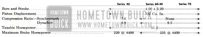
1956 Buick Engine Specifications
2-1 COMPRESSION RATIO AND HORSEPOWER
The Series 40 engine used with the synchromesh transmission has a compression ratio of 7.6 to 1. The Series 40 Dynaflow engine has a compression ratio of 8.9 to 1. The different Compression ratios of the synchromesh and Dynaflow engines are obtained by using pistons with two different dome heights.
The maximum horsepower of the 40 Series Dynaflow engine has been increased from’188 in 1955 to 220 in 1956, or an improvement of 16 %.
The 1956 engines used on the 60-50-70 Series have a compression ratio of 9.5 to 1 and the maximum engine horsepower has been increased from 236 in 1955 to 255 in 1956, or an improvement of 8 %. See Figure 2-1.
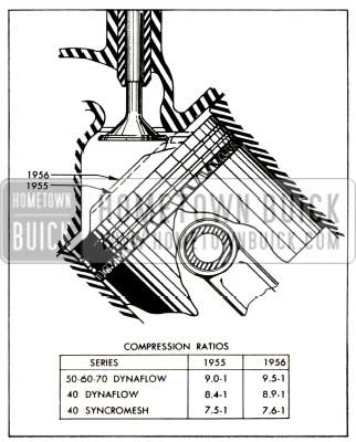
1956 Buick Comparison of 1955 and 1956 Compression Ratios
A combination of engineering features has increased power on the 1956 engines. They are increased compression ratios on all series, the new “Y” type exhaust manifolds, new camshafts and exhaust valves, and combustion chamber alterations. These features have substantially increased thermal efficiency.
2-2 CONNECTING RODS, PISTONS, AND CYLINDER HEADS
Connecting rod s with pressed in type wrist pins were introduced as a 1955 after job and will continue in the 1956 engine. This new type rod excludes the pinch bolt formerly used, thereby eliminating the possibility of the bolt breaking or loosening. See Figure 2-2.

1956 Buick Comparison of 1955 and 1956 Connecting Rods
The servicing procedure for the pressed-in type wrist pin was covered by BPS 2.393 dated August 15, 1955.
The height of the piston dome for 1956 has been increased and the slope of the dome on the valve side has been changed to 30 degrees. This accounts for the increased compression ratio previously covered. Also, the metal inside the piston has been redistributed for added strength. See Figure 2-3.
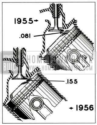
1956 Buick Comparison of 1955 and 1956 Combustion Chambers
The cylinder head combustion chamber has been relieved on the valve side for improved breathing.
2-3 CAMSHAFT AND VALVES
The intake valves on all 1956 engines remain unchanged, however, the exhaust valve has been redesigned. The exhaust valve has a new “tulip shaped” head. This type valve reduces restriction to flow and thus increases power output. Added features are flexibility of valve head for better seating and decreased weight. The valve seat angle specification remains 45 degrees as in 1955. See Figure 2-4.
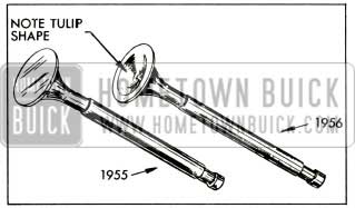
1956 Buick Comparison 1955 and 1956 Exhaust Valves
A cast iron alloy camshaft with an increased exhaust cam lift will be employed in synchromesh engines for 1956. The exhaust valve timing has been modified to open five degrees earlier than in 1955.
There will also be a cast iron alloy camshaft for all Dynaflow engines in 1956. The valve timing for this engine has been modified in that the exhaust valve opens three degrees earlier and closes two degrees later and the intake valve opens two degrees earlier and closes three degrees later in 1955.
These modifications have resulted in an increase in horsepower due to improved volumetric efficiency.
2-4 HYDRAULIC LIFTERS
Buick will in 1956 utilize two new cast iron alloy hydraulic lifters. Both lifters will be functionally the same as in the past, but it must be carefully noted that there are no interchangeable parts. The lifter plunger will have an increased length over the 1955 lifter with a resultant reduction in push rod length.
The primary differences between the two types of 1956 lifters are as follows:
Type “A” identified by the one, two, or three ridges around the indented portion of the lifter body has a thick body wall and relatively small plunger. See Figure 2-5.
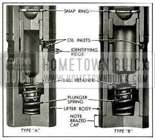
1956 Buick Cross Sections-1956 Hydraulic Lifters
It is a one-piece body production lifter. Type “B” identified by the smooth surface of the indented portion of the body is of two piece construction having the upper portion made of steel tubing and the foot of cast alloy iron. It has a thin body wall, and a relatively large plunger.
The 1956 lifters cannot be used in the 1955 engine and the 1955 lifters cannot be used in the 1956 engines. The primary reason for this is that the 1955 forged steel camshaft is not compatible with the 1956 cast iron alloy lifters, nor is the 1956 alloy iron camshaft compatible with the 1955 chilled iron lifters. The different push rod lengths also prevent the possibility of interchanging. However, the two 1956 lifters are interchangeable with each other.
It is no longer necessary to measure check ball travel of hydraulic lifters. However, the leakdown rate specification remains at 9 to 30 seconds. See Figure 2-5.
Because both 1956 lifters have longer plungers, a new adapter is required when using Hydraulic Valve Lifter Leak-Down Tester J-5200-A. The Ram Adapter J-5180-15 will be used for checking leak down rate.
2-5 WATER PUMP
There have been three small modifications in the water pump for 1956. The six blade impeller used in 1955 has been replaced by a three blade impeller with a .060 inch added clearance between the blade and the timing chain cover. The new pump has an increased flow capacity of 16 % at 2000 RPM. The bearing retainer snap ring and water slinger used in 1955 have been eliminated. This has been made possible by increasing the press fit between the bearing and the water pump cover. The fan hub, seal sleeve, and impeller are pressed onto pump shaft. Locating specifications remain the same as in 1955.
Leave A Comment
You must be logged in to post a comment.