4-1 CLUTCH
A new single plate, dry disc clutch is used in cars equipped with synchromesh transmissions. The clutch is of the conventional design with coil type clutch springs and three release levers.
The clutch cover is bolted to the flywheel and three lugs on the pressure plate engage slots in the cover to transmit torque to the plate. Nine clutch springs are located between the cover and the pressure plate. The three clutch release levers are located so that their inner ends are in position to be engaged by the clutch release bearing. The levers pivot on fulcrums formed at the clutch cover where they pass through it. The outer ends engage the three pressure plate lugs. Removal and replacement procedures are the same as used in 1955. The clutch pressure plate, cover, springs and levers are serviced as an assembly only, and these parts cannot be purchased individually.
4-2 CLUTCH OPERATING LINKAGE
Description
Buick in 1956 will employ a suspended type clutch pedal mounted on a hinge bracket welded to the dash panel. The pedal pivots on a nylon bushing enclosed in the upper end of the pedal at the hinge. Pedal movement is transmitted to the equalizer assembly through a steel rod. This rod is retained at the pedal end by a nylon ball socket and is connected at the equalizer end with an adjustable clevis. The purpose of the adjustable clevis is to correctly position the equalizer assembly in relation to the overcenter spring. The pedal is maintained at a predetermined height by a steel washer and a clutch pedal bumper located by a snap ring on the pedal rod. This washer-bumper assembly acts as a pedal stop when contacting the toe pan. See Figure 4-1.
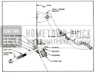
1956 Buick Suspended Pedal
The equalizer assembly is bracketed at the left end to the left frame member and on the right to the engine. See Figure 4-2.
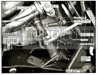
1956 Buick Clutch Linkage
The equalizer assembly is connected to the clutch release yoke by a clutch release rod. A clutch return spring is attached between the equalizer assembly and the splash pan. The pedal lash adjustment is on the clutch release rod and the method of adjustment remains the same as in 1955.
Clutch Pedal Lash Adjustment
- Make certain that the return spring pulls the clutch pedal bumper firmly against the toe-pan when the pedal is released.
- Check the clearance between the equalizer assembly and the overcenter spring extension. A clearance of 1/16 to 1/8 inch (slip fit on 3/32 inch allen wrench) should be maintained to provide for proper operation. See Figure 4-3.
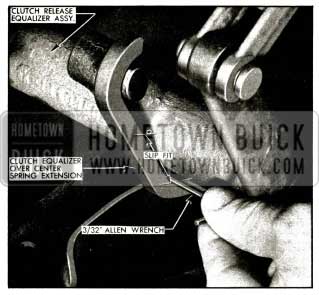
1956 Buick Checking Clearance Between Equalizer Assembly and Overcenter Spring Extension
If adjustment is necessary, loosen the clutch pedal to equalizer rod lock nut and turn rod until the desired clearance is obtained.
- Check the pedal free movement or lash by pushing on the pedal pad until contact can be felt between the release bearing and the clutch springs. Free movement or lash of clutch pedal should be 7/8 inch measured at the pedal pad. If adjustment is necessary, loosen clutch release rod lock nut and turn adjusting nut as required to secure proper lash. Tighten nut securely.
4-3 TORQUE BALL
The new torque ball has two bonded rubber contact rings on the ball faces which are compressed between steel inner and outer retainers. All motion of the ball is taken by flexing of the rubber, which forms an oil-tight seal. A reinforcement is used under the bolt heads to avoid distortion of the retainers. No shim adjustment is required on bonded rubber torque ball.
Removal and Installation of Torque Ball
- Disconnect rear axle assembly and move it back out of the way. See Par. 6-4, a.
CAUTION: Be sure torque ball retainer bolts are loose and torque tube guide pins are installed before moving axle assembly back to avoid damaging propeller shaft seal.
- Remove retainer bolts, reinforcement, torque ball, retainers and gaskets from transmission rear bearing retainer. See Figure 4-4.
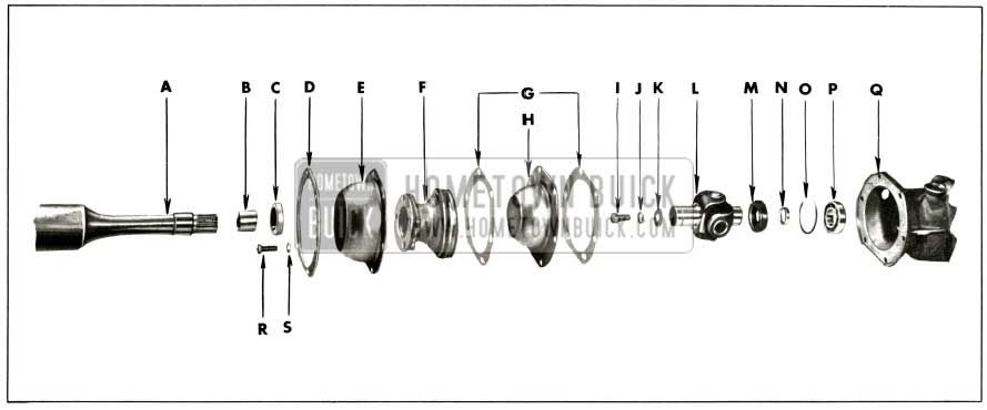
1956 Buick Torque Ball Assembly
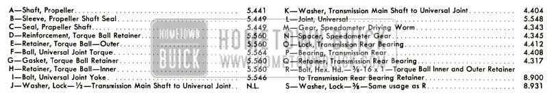
1956 Buick Torque Ball Assembly Legend
Leave A Comment
You must be logged in to post a comment.