SECTION 5-A DYNAFLOW SPECIFICATIONS, DESCRIPTION AND OPERATION
5-1 DYNAFLOW SPECIFICATIONS
General Specification
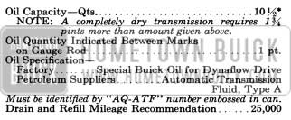
1956 Buick Dynaflow Specifications
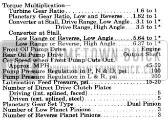
1956 Buick Dynaflow Specifications and Description
The complete General Specifications Section for the 1956 Dynaflow is given below. Changes or additions are indicated with an asterisk (*).
Tightening, Test and Assembly Specifications
- Tightening Specifications.
Use a reliable torque wrench to tighten the attaching bolts or nuts of the parts listed below. These specifications are for clean and lightly lubricated threads only; dry or dirty threads produce increased friction which prevents accurate measurement of tightness.
- Test and Assembly Specifications.
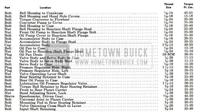
1956 Buick Dynaflow Torque Specifications
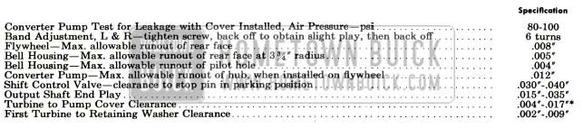
1956 Buick Dynaflow Test and Assembly Specifications
5-2 DYNAFLOW PRODUCTION LIMITS AND FITS OF NEW PARTS
NOTE: These specifications apply to new parts only and must be used with discretion when checking worn-in parts. The limits e stablished for new parts allow for reasonable wear through normal use; therefore, parts which have been in service and have been operating satisfactorily should not be re placed simply because they slightly exceed the limits specified for new parts.
- Converter Assembly

1956 Buick Converter Assembly Specifications
1956 Buick Front Oil Pump Specifications
1956 Buick Reaction Shaft Flange Specifications
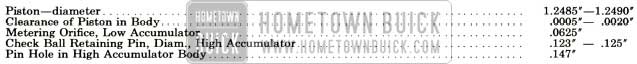
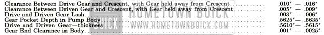
1956 Buick Accumulators Specifications
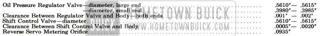
1956 Buick Valve and Servo Body Assembly Specifications
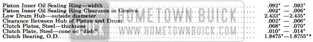
1956 Buick Clutch Specifications

1956 Buick Power Steering Pump Specifications
1956 Buick Planetary Gear Set and Reverse Ring Gear Specifications View
1956 Buick Rear Oil Pump Specifications
1956 Buick Rear Bearing Specifications
Test Pressures, Oil Pumps and Accumulators
The following pressures are based on initial tests only. Revised figures, if necessary, will be covered in a later BPS publication.
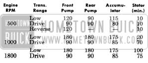
1956 Buick Dynaflow Test Pressures
5-3 GENERAL INFORMATION
Major New Features
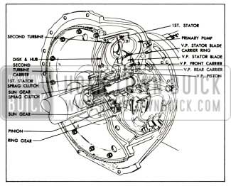
- To increase low speed performance under full throttle, and to provide a more solid feel under part throttle or normal acceleration, a new stator has been added. This new stator is called the first stator. The vanes of this stator are located between the first and second turbines. See Figure 5-l and Figure 5-2.
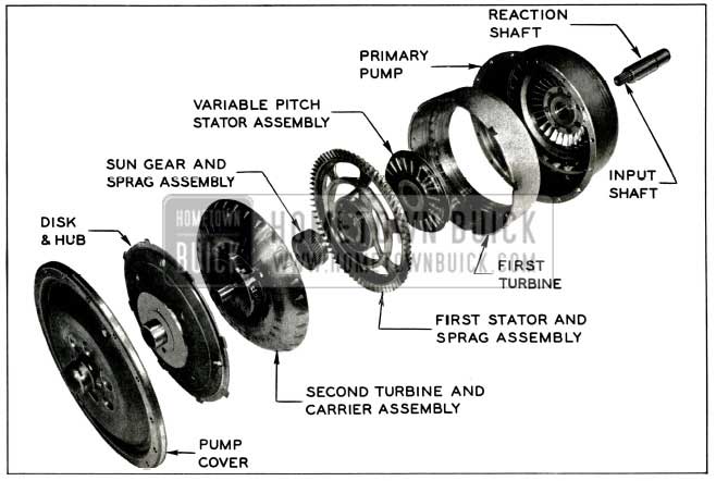
1956 Buick Major Components of 1956 Torque Converter
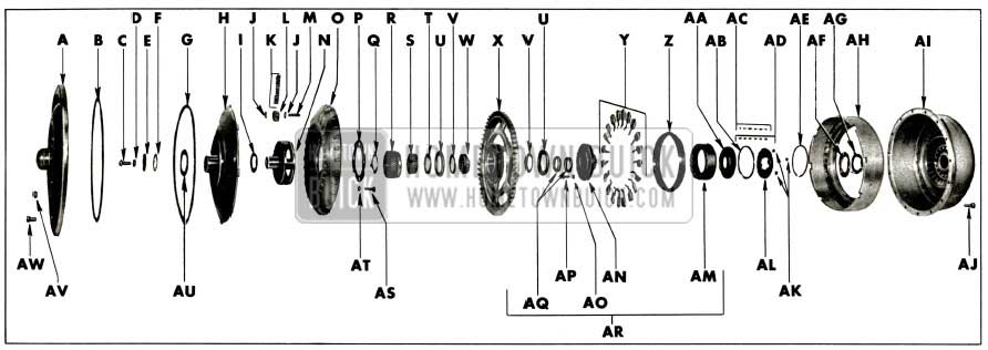
1956 Buick Torque Converter
1956 Buick Torque Converter Legend
Other Changes
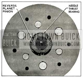
- A new needle thrust bearing is used in the 1956 Dynaflow between the low range reaction gear and reverse sun gear. The new bearing is used in conjunction with a steel selective fit washer in the end of the low range reaction gear to obtain proper output shaft end play. The new needle bearing has greater durability than the bronze thrust washer previously used. See Figure 5-3.
1956 Buick Needle Thrust Bearing
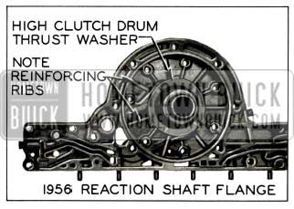
1956 Buick Reaction Shaft Flange
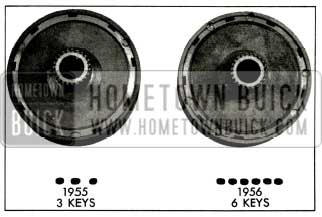
1956 Buick Low Range Reaction Gear and Keys
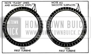
1956 Buick Dynaflow First Turbine
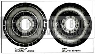
1956 Buick Dynaflow Aluminum and Steel Second Turbine
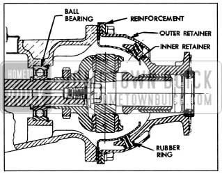
1956 Buick Dynaflow Rear Bearing and Torque Ball
Stall speeds and torque ratios of the Dynaflow transmission for the past few years, incorporating different converters, are given in the following table:
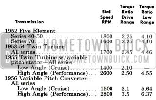
1956 Buick Stall Speeds
The new variable pitch Dynaflow torque converter automatically provides the proper ratio of torque multiplication to meet the varying demands imposed by starting and driving under all ordinary conditions of load and grade, in addition to added performance for acceleration and passing when needed.
5-4 DYNAFLOW MANUAL CONTROL MECHANISM AND OPERATING INSTRUCTIONS
The only important difference in the manual controls for the 1956 Dynaflow is that low stator blade angle exists in all ranges at part throttle and can be changed to high angle by fully depressing the accelerator pedal.
5-5 DYNAFLOW VARIABLE PITCH TORQUE CONVERTER
Converter Pump and Cover
The converter pump and cover are essentially the same as in 1955; however, the pump is not interchangeable due to dimensional changes to accommodate the first stator.
Twin Turbine Assembly
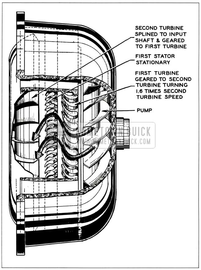
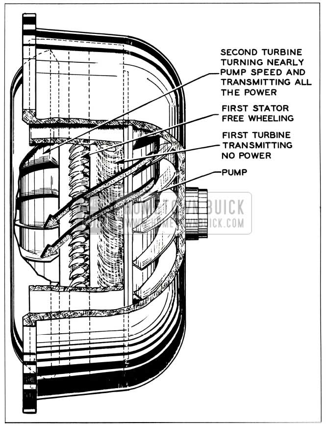
The turbine assembly is coupled to the transmission input shaft through which torque is transmitted to the direct drive clutch and the planetary gears located to rear of torque converter. The Twin Turbine assembly consists of a first turbine, a first stator, a second turbine, and a planetary gear set that connects the first turbine to the second turbine.
The first turbine has a narrow band of vanes located at the pump exit in a position to receive the spinning cylinder of oil projected from the pump. The first stator has a similar band of narrow vanes located between the first turbine and the second turbine. The second turbine is located inside the first turbine in position to receive oil directed to it from the first turbine and first stator. This turbine has a broad band of vanes shaped to direct the oil flow back into the variable pitch stator in a direction opposite to converter rotation.
The second turbine is bolted to a carrier which is splined to the input shaft; therefore, the second turbine and input shaft rotate at the same speed. The first turbine is mounted on a disk and hub assembly which has a bearing on the hub of the turbine carrier. This turbine is connected to the carrier and input shaft through planetary gears. Therefore, its speed relative to the input shaft is governed by gear action.
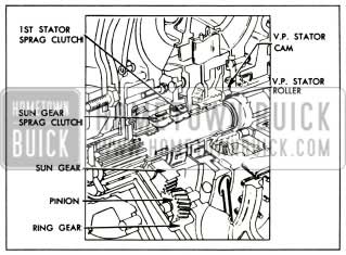
The first turbine hub contains internal ring gear teeth which mesh with four planet pinions mounted in the turbine carrier on steel pins and needle bearings. The planet pinions mesh with a sun gear supported by a bearing on the stationary reaction shaft which is anchored to a flange bolted between the bell housing and the transmission case. The sun gear contains a sprag type free wheel clutch which operates to hold the gear stationary when turbine gear reduction is required for increased torque multiplication and permits the gear to free wheel when gear reduction is not required. See Figure 5-9.
1956 Buick Variable Pitch Torque Converter
When engine is accelerated with car stationary, oil is emitted from the first turbine in a direction opposite pump rotation into the first stator which redirects the oil into the second turbine in the same direction as pump rotation, thus providing increased torque multiplication during acceleration.
The first stator is supported on the reaction shaft by two bronze bearings, one on each side of a sprag type free wheel clutch which holds the stator stationary when torque multiplication is required (up to approximately 30 mph at full throttle) and allows the stator to turn with the pump when torque multiplication is not required. See Figure 5-10.
1956 Buick Converter Gean and Clutches
The function of the turbine assembly is to absorb energy from the oil projected into it by the pump and convert the energy into torque as determined by engine speed and load conditions.
Variable Pitch Stator
The general construction and function of the 1956 variable pitch stator assembly is the same as the stator used in late 1955 production. However, the blade angle has been changed slightly and the blades are not interchangeable with 1955 stator blades. The 1956 blades are identified by a small rectangular mark stamped on the inner end of the stator blade crank. For description of variable pitch stator operation see Paragraph 5-6 (c) of the 1955 Shop Manual.
Operation of Torque Converter
Operation of the torque converter is the same in Direct Drive, Low and Reverse. The variable pitch stator is in the low angle position at part throttle and in the high position at full throttle. The converter transmits torque to the direct drive clutch and planetary gears through the transmission input shaft. The range of transmission operation is determined by control of the clutch and gears as described in paragraph 5-7 of the 1955 Shop Manual.
Description of torque converter operation will begin with the car stationary, transmission in Direct Drive, and engine running at idling speeds. At this point the converter pump is slowly turning with the engine and the turbine members are stationary.
The engine driven converter pump projects a rotating cylinder of oil into the first turbine, the vanes of which are shaped in such a manner that oil leaving them is directed backward into the first stator. The sprag type clutch on which the stator is mounted prevents stator from turning backward, causing the vanes to redirect the oil into the second turbine in the same direction as pump rotation.
At idling speed the force of oil flow against vanes is not sufficient to move either turbine and the oil flows through the first turbine, first stator and second turbine into the variable pitch stator without transmitting any appreciable amount of torque.
As the oil emerges from the second turbine near its center, the backward curvature of the exit ends of the vanes causes the oil to spin backward with reference to pump rotation as it flows into the variable pitch stator. Pressure of oil against the forward face of the stator blades causes the free wheeling clutch to lock and hold the stator stationary. The curved stator blades then change the direction of flow so the oil enters pump rotating in the same direction as the pump is turning.
When the throttle is open the engine speeds up and rapidly approaches its torque peak. With increased speed, the converter pump now projects a large volume of oil into the turbines at high rotary speed. The rotating cylindrical mass of oil may be compared to a spinning flywheel rim. A spinning flywheel has stored up energy (turning force) which may be transmitted to any mechanism which opposes its rotation. Since the vanes of both turbines oppose rotation of the spinning flywheel of oil projected from the pump the stored up energy in the oil exerts a powerful impulsion force against the vanes tending to rotate the turbines in the same direction as the pump.
At this stage the impulsion force of the oil against the vanes is not sufficient to move either turbine. The oil flows through the turbine channels and is discharged into the stator, which redirects it into the pump entrance. As the oil emerges from the second turbine into the stator, spinning at high speed in a reversed direction, it exerts a powerful reaction force against the turbine vanes, tending to rotate the turbine in the same direction as the pump.
Engine torque applied to the converter pump generates a given amount of energy in the oil projected from the pump against the turbine vanes. When the turbines are stationary, the oil passes through both turbines and the stator and returns to the pump with almost as much energy as when projected. The amount of energy in the oil thereafter projected from the pump becomes the sum of the energy in returning oil plus the energy resulting from engine torque application, or almost double the amount of energy that could be generated by engine torque alone. The greatly increased energy in the spinning flywheel of oil then projected into the turbines produces a corresponding increase in the impulsion and reaction forces upon the turbine vanes.
The described build-up of forces produces a turning force or torque upon the turbines which is much greater than the torque produced by the engine; therefore, torque multiplication is accomplished. It would seem that torque multiplication would increase indefinitely as the cycle repeats itself, but mechanical factors limit the increase of torque multiplication beyond a definite ratio in any given torque converter design.
The build-up of forces against the turbine vanes causes the first turbine to rotate in the same direction as the converter pump. The first turbine absorbs part of the energy transmitted by the oil stream and converts this energy into torque, which is imparted to the ring gear in its hub. The ring gear rotates the planet pinions, causing them to “walk” around the stationary sun gear so that turning force is applied to the turbine carrier in which the pinions are mounted.
Oil is projected from the first turbine against the front (concave) face of the first stator blades. As the stator is prevented from turning against pump rotation by the action of the sprag clutch, the blades change the direction of oil flow into the second turbine spinning in the same direction as pump rotation, thus providing torque multiplication at low car speeds. See Figure 5-11.
1956 Buick Oil Flow from Pump to Second Turbine on Acceleration
As first turbine speed more nearly approaches engine speed and the torque multiplication requirements are less, the angle at which oil emerges from the first turbine changes, striking the rear (convex) face of the first stator blades, causing the stator to turn freely on the reaction shaft thus allowing oil to flow unimpeded from the first turbine into the second turbine. See Figure 5-12.
1956 Buick Oil Flow from Pump to Second Turbine While Cruising
The second turbine absorbs energy from the oil stream after it leaves the first turbine and converts this energy into torque which is also imparted to the turbine carrier, on which this turbine is mounted. The turbine carrier transmits the torque of both turbines to the input shaft to which it is splined. See Figure 5-9.
The turbine planetary gear set gives a ratio of 1.6 to 1 when the sun gear is stationary and this reduction gearing increases the torque transmitted through the first turbine. The overall operation of the converter at low angle provides a maximum torque multiplication of approximately 3.10 to 1 at stall (car stationary and engine accelerated under load). Usually the car may be started with appreciably less than the maximum torque multiplication that is available through the converter.
As the car gains speed and momentum the demand for torque decreases so that the applied torque causes turbine speed to rapidly approach pump speed. As this occurs it is essential for torque multiplication to taper off so that car speed can be maintained at a lower, more economical engine speed. Tapering off occurs automatically because centrifugal force generated in the rapidly rotating mass of oil in the turbines creates an outward counter force which opposes the flow of oil from the pump. Reduction of oil flow and pump output energy effects a decrease in the impulsion and reaction forces upon the turbines so multiplication of engine output torque tapers off as turbine speed increases.
Reduction in speed differential between turbines and pump reduces the torque reaction on the sun gear until this reaction is entirely eliminated. The sun gear then free wheels and the first turbine ceases to be effective. As speed of the second turbine increases, the direction of oil flow into the variable pitch stator correspondingly changes toward the rear face of the stator blades, thus gradually eliminating the force holding the stator stationary. Pressure of oil against rear face of blades causes the stator to free wheel at sufficient speed so that it does not interfere with flow of oil between second turbine and pump.
At this point the torque converter functions as an efficient fluid coupling, transmitting torque at a 1 to 1 ratio. Sufficient speed differential remains between pump and turbines to enable transfer of oil from pump to turbines where the oil gives up energy and returns to the pump for recirculation.
The operation described has occurred without reaching wide open throttle operation, therefore the variable pitch stator blades have remained in the low angle “cruising” position. If the accelerator pedal is pressed to floor mat at any time, the variable pitch stator blades will be shifted to the high angle “performance” position through the hydraulic control action described in paragraph 5-6. In this position the stall speed and torque multiplication of converter are increased, providing improved performance for acceleration or pulling under load.
The various stages of the stators and turbines in the operation described do not occur at set speeds but are dependent on torque requirements imposed by car operating conditions. With light load and steady driving, torque multiplication may cease at very low car speeds, but with continued acceleration some degree of torque multiplication may be present throughout the major portion of the car speed range. When the torque converter is operating as a fluid coupling and car operating conditions change so that increased torque is demanded, the converter automatically adjusts itself to meet the demand without any manipulation of controls by the driver.
When the drive through the torque converter is reversed on deceleration or when descending grades, the converter functions as a fluid coupling to permit effective engine braking. It also functions as a fluid coupling when the car is pushed in Low range to crank the engine.
5-6 DYNAFLOW HYDRAULIC CONTROL SYSTEM
- The 1956 oil pump pressure regulator valve and valve body have been modified to allow oil under pressure to be supplied to the stator control valve at all times, thus providing a means to alter the variable pitch stator blade angle in Low and Reverse as well as Drive range.
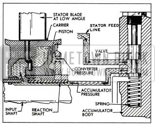
- The 1956 variable pitch stator control valve incorporated in the high accumulator housing is supplied with oil at front pump pressure below approximately 45 miles per hour and with oil from the rear pump above 45 miles per hour. Normally this valve is held upward by a spring so oil can pass into the stator carrier on the front side of the piston. Since this pressure is greater than converter charging pressure existing on the rear side of the piston, the piston moves rearward to hold the stator blades in the low angle “cruising” position. This provides a low stall speed (1500 R.P.M.) and torque multiplication of 3.1 to 1, which provides a solid drive feel for all normal operating conditions.
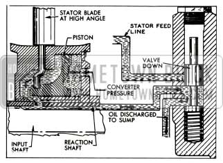
When the accelerator pedal is pressed to the floor mat the throttle control linkage actuates other linkage connected to the stator control valve so the valve is pushed down thereby shutting off oil to the front side of the stator piston and opening a passage to discharge oil from the front side of the stator piston. Converter charging pressure then moves the piston forward, which rotates all blades approximately 75° from the low angle position. See Figure 5-14.
1956 Buick Stator in Low Angle Position
1956 Buick Stator in High Angle Position
This high angle “performance” position will give the converter a higher stall speed (2800 R.P.M.) and torque multiplication ratio of 3.5 to 1 providing improved acceleration and pulling power under load. The transition from low angle to high, or high angle to low is very smooth.
SECTION 5B REVISED SERVICE PROCEDURES FOR THE 1956 DYNAFLOW TRANSMISSION
5-7 REMOVAL AND INSTALLATION OF DYNAFLOW TRANSMISSION
Removal procedures remain basically the same as in 1955 except the oil cooler pipes are removed completely before the transmission is removed from the car.
Installation procedure is basically the same as in 1955 except the normal weight of the car must be on all four wheels before the torque ball bolts are tightened. Carefully follow procedure outlined in Paragraph 4-3 of this manual.
5-8 DISASSEMBLY OF DYNAFLOW TRANSMISSION TO REMOVE MAJOR PARTS AND UNITS
Dynaflow disassembly remains basically the same with the following exceptions which will be explained only as far as they differ from the 1955 Shop Manual.
Removal of Converter and Bell Housing
Removal of converter and bell housing as outlined in Paragraph 5-14 (b) of the 1955
Shop Manual is the same except step No. 5 is eliminated because the sun gear is removed with the turbine assembly.
Removal of Torque Ball and Universal Joint
- Remove attaching bolts, then remove torque ball, inner and outer retainers reinforcement and gaskets.
- Remove speedometer driven gear and sleeve assembly.
- Place transmission shift lever on cross shaft and push lever forward while turning universal joint until locking pawl engages the parking lock ratchet wheel.
- Remove universal joint bolt, lock washer and flat washer, using a %” socket wrench and extension.
- Pull universal joint from output shaft using puller J-682-A if joint cannot be removed by hand.
- Remove universal joint spacer.
- Remove transmission shift lever.
Removal of Planetary Gear Set Reverse Ring Gear and Reverse Band
This operation is identical as outlined in Paragraph 5-14 (h) of the 1955 Shop Manual, except there is no planet carrier thrust washer in the 1956 Dynaflow.
5-9 DISASSEMBLY, INSPECTION, ASSEMBLY OF TORQUE CONVERTER
This operation is covered completely below, as the procedure varies somewhat from the 1955 Shop Manual.
Disassembly of Twin Turbine
- Pry retaining ring out of groove in first turbine, insert screwdriver in a hole in the disk and lift disk and hub assembly out of first turbine. See Figure 5-15.
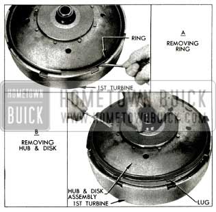
1956 Buick Removing Disk and Hub Assembly
- Lift the second turbine and carrier assembly out of first turbine.
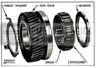
- Remove tanged thrust washer. (This washer may remain in carrier or be found on top of the sun gear.)
- Slide the sun gear assembly off the first turbine being careful to hold sun gear bearing in place.
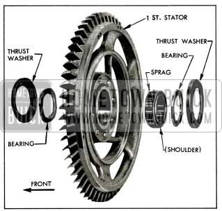
- Lift first stator assembly out of first turbine.
- Remove the bronze bearing and sprag from the sun gear.
- Lay first stator on bench with narrow edge of vanes up.
- Pry off cupped thrust washer.
- Remove first stator bearing and sprag assembly.
- Using a brass drift, carefully tap first stator bearing to remove bearing and cupped thrust washer.
1956 Buick Second Turbine Parts
1956 Buick Sun Gear Parts
1956 Buick First Stator Parts
Disassembly of Variable Pitch Stator
- Remove stator thrust washer and selective spacers from rear side of stator, remove Tool J 5806, then remove free wheel rollers and springs from the cam.
- Pry the retaining ring from groove in stator blade rear carrier, and remove free wheel cam and three driving keys. See Figure 5-19.
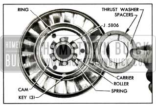
1956 Buick Parts in Rear Side of Stator
- Use Screwdriver J 5826 to remove the stator blade front carrier screws and lockwashers, then remove front carrier which is also held to rear carrier by two dowels. See Figure 5-20.
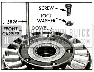
1956 Buick Removing Front Carrier Screws
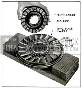
1956 Buick Front of Stator Assembly
- Tilt three or four blades toward the low angle position and slide the crank pin ends clockwise around the stator piston groove. The next blade and all succeeding blades will then have enough clearance to be removed. See Figure 5-22.
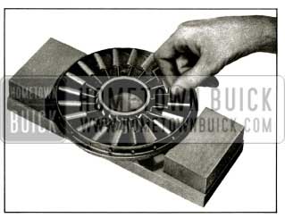
1956 Buick Stator Blades Being Removed
Inspection of Torque Converter Parts
- Wash all parts in clean solvent and dry thoroughly.
- Inspect converter pump hub for scores and for wear caused by the front pump seal. If pump is suspected of leaking oil it may be tested as described in subparagraph d, below.
- Inspect converter pump and turbines for cracked or damaged vanes.
- Inspect turbine carrier, planetary gear teeth, thrust washer, bushings and related bearing surfaces for excessive wear, scoring or other damage.
- Inspect stator free wheel rollers and cam for nicks or burrs, which should be removed with an Arkansas stone and polished with crocus cloth. Discard any roller springs that are damaged or distorted.
- Inspect stator blades for distortion, cracks, loose on cranks, or other damage.
- Inspect piston oil seal ring and bore of blade carrier for scoring or wear. If bushings in carrier are worn they should be replaced, using Installer J 5913 to properly locate new bushings. See Figure 5-23.
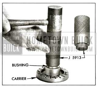
1956 Buick Installing Bushing in Blade Carrier
- If second turbine or the carrier must be replaced, use care in separating them to avoid damage to the good part.
With second turbine suitably supported, tap carrier free of counterbore in turbine, using hammer and a hardwood dowel or other soft punch. Do not drive against surface of thrust boss in carrier. See Figure 5-24.
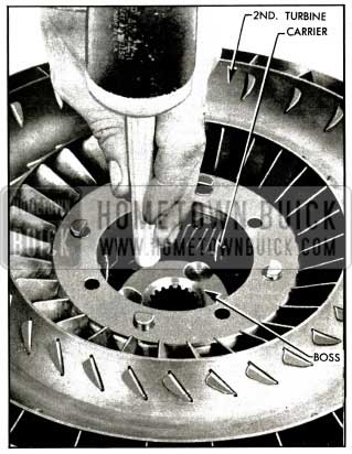
1956 Buick Removing Second Turbine Carrier
Testing Converter Pump for Oil Leakage
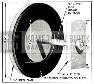
- Prepare a plate with rubber washer to close the opening in converter pump hub, as shown in Figure 5-25.
1956 Buick Plate and Washer for Pump Test
The bolt head should be brazed to the plate to seal the bolt hole, and the 1/8” thick rubber washer should be cemented to the plate.
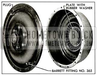
- Install plate with washer over inside surface of pump hub (Figure 5-26, then install pump cover with seal and tighten all bolts to 25-30 ft. lbs. torque in sequence shown in Figure 5-105 of the 1955 Shop Manual.
- Install one drain plug, and install a Barrett fitting No. 365 in other drain hole. Tighten parts securely. See Figure 5-26.
1956 Buick Pate and Plugs Installed in Pump and Cover
- Attach air hose to Barrett fitting, fill pump with compressed air at 80 to 100 lbs., sq. in. and submerge pump in water tank. Air bubbles will appear at any point where oil leakage exists.
CAUTION: After a pump cover seal -is used in this test it should not be used when rebuilding transmission.
Assembly of Variable Pitch Stator
- Insert stator piston and oil seal ring in the rear carrier and push to extreme forward position.
- Place the rear carrier and piston on center block of fixture to hold the piston in position. See suggested fixture shown in Figure 5-27.
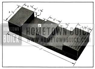
1956 Buick Variable Pitch Stator Assembling Fixture
- Place the stator outer ring on 2 outer blocks of fixture with crank pin holes up. See Figure 5-28.
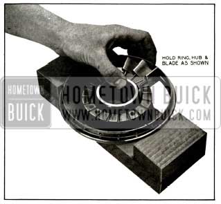
1956 Buick Inserting Stator Blades in Carrier
- Holding the blade in the approximate “low pitch” position insert the crank pin in the outer ring. Then rotate the blade to bring the crank throw into the piston groove. Hold the piston, blades, outer ring together as shown in Figure 5-28.
- Install the remainder of the blades, working in a clockwise direction.
- To insert the last blade it will be necessary to tilt the adjacent 3 blades. See Figure 5-29.
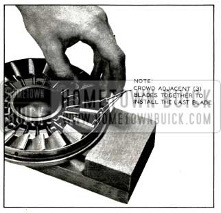
1956 Buick Inserting Last Blade
- Install the front carrier and bolt in place. Be sure the blades operate freely in the carrier.
Assembly of Sun Gear and Twin Turbine
- Install sprag in bore of sun gear with shouldered end outward then carefully press the bearing in place. See Figure 5-17.
- Check operation of sun gear sprag clutch by sliding sun gear assembly on reaction shaft with gear end toward front of transmission. Sun gear must rotate freely clockwise and lock in a counter clockwise direction when viewed from front of transmission.
- Lay first stator on bench with thin edges up. Place first stator sprag in hub of first stator with shoulder down. Install one bronze bearing and cupped thrust washer on each side of sprag. See Figure 5-18.
- Check operation of first stator sprag clutch by sliding the first stator on the reaction shaft with thin edge of blades toward front of transmission. The first stator must turn freely clockwise and lock in a counter clockwise direction when viewed from front of transmission.
- If second turbine was separated from the carrier, make certain that counterbored recess in turbine and mating surfaces of carrier are clean and free of burrs, and apply a film of oil to these surfaces.
- Support the carrier on suitable blocks, install several pinion pins to serve as pilots, then place turbine in position so that carrier is squarely started into recess in turbine.
- Use a hammer and hardwood dowel or other soft punch to tap the turbine down over the carrier. Avoid distortion of turbine by using light blows applied midway between holes and alternated from side to side to keep parts square with each other. See Figure 5-30.
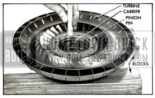
1956 Buick Installing Turbine on Carrier
NOTE: If turbine cannot be assembled on carrier with moderate force, remove it and check for burrs in counterbored recess.
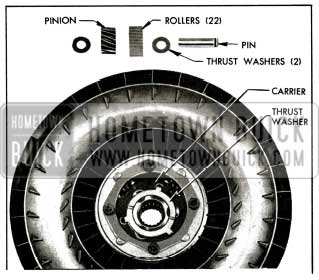
- With turbine and carrier supported on wood blocks, hub side down, assemble and install the four pinions as follows:
- Place planet pinion on a thrust washer, install 22 needle bearing rollers in pinion and place a thrust washer on top of pinion.
NOTE: A loading tool made locally of steel rod 3/8″ in diameter by 11/16″ long will simplify loading and installation of pinion. See Figure 5-31.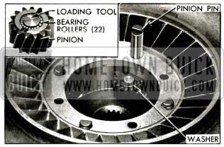
1956 Buick Installing Pinion in Carrier
- Place assembled pinion in carrier and install a pinion pin with notched end up. After loading tool is pushed out of carrier, slide a block under pinion pin to hold it in place. Turn all pins so that notches face center of carrier. See Figure 5-31.
- Place planet pinion on a thrust washer, install 22 needle bearing rollers in pinion and place a thrust washer on top of pinion.
- Install pinion pin lock plate so that it enters the notches of all pins, then install the four turbine-to-carrier bolts with lockwashers. See Figure 5-16.
- Place first stator in first turbine with thin edge of blades up.
- Place sun gear assembly on first stator with gear end up.
- Place thrust washer (with tangs) in planet carrier. Use chassis lube to prevent the washer from shifting during assembly.
- Place second turbine and carrier assembly in first turbine. Be sure pinions mesh with sun gear.
- Place thrust washer on carrier.
- Install first turbine disk and hub assembly over second turbine.
- Rotate disk until the ring gear meshes with the carrier pinions, then align driving lugs on disk with notches in first turbine and push the assembly all the way down into turbine.
- Note that the turbine disk retaining ring is “dished.” Place the ring in position with the “dish” upward so that the inner edge will bear firmly against the disk when the ring is engaged in the groove in first turbine. See Figure 5-32.
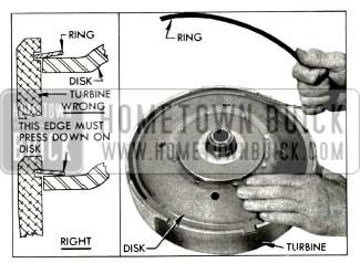
1956 Buick Installing Disk Retaining Ring
- Start one end of ring into groove in turbine, then twist the ring upward as shown in Figure 5-32 to lay the ring fiat on the disk so that it can be progressively entered into the groove all the way around.
- Make certain that the ring is fully seated in the groove and that inner edge bears against the turbine disk. Tap inner edge down against disk if it has raised up.
5-10 WITH THE FOLLOWING EXCEPTIONS, ALL REMAINING SERVICE OPERATIONS ON THE 1956 DYNAFLOW ARE THE SAME AS 1955 LATE MODEL DYNAFLOWS:
Ball Bearing Rear Bearing
The 1956 rear bearing is held in place by a snap ring. The new ball bearing can be removed by following this procedure:
- Remove rear bearing retainer.
- Remove rear bearing snap ring.
- Tap out bearing.
To install, reverse this procedure.
Low Range Reaction Gear Needle Thrust Bearing
To replace the Low range reaction gear, needle thrust bearing (between reverse sun gear and Low range reaction gear) it will be necessary to disassemble the planetary gear set as described in Paragraph 5-22 of the 1955 Shop Manual. After the front and rear ends of the planet carrier have been separated and the sun gear removed, the needle thrust bearing may be removed and/or replaced.
Leave A Comment
You must be logged in to post a comment.