6-1 REAR AXLE SPECIFICATIONS
Tightening Specifications
Use a reliable torque wrench to tighten the parts listed, to insure proper tightening without straining or distorting parts. These specifications are for clean and lightly lubricated threads only; dry or dirty threads produce increased friction which prevents accurate measurement of tightness.
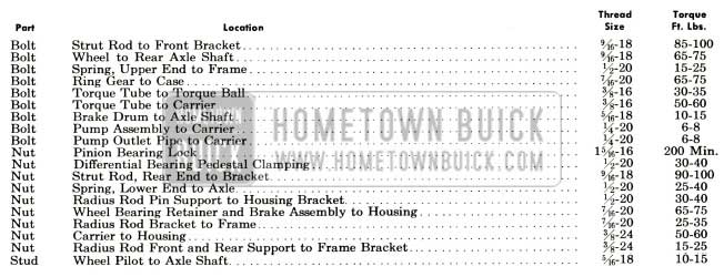
1956 Buick Rear Axle Specifications
General Specifications
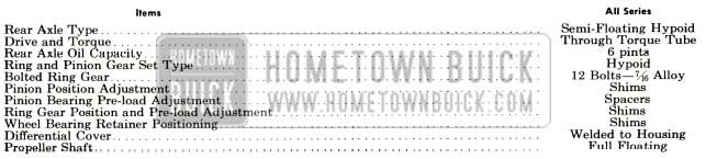
1956 Buick Rear Axle General Specifications
Rear Axle Gear Ratios
The following gear ratios are standard; optional gear ratios are not available.
1956 Buick Rear Axle Gear Ratios
The gear ratio is indicated by numbers stamped on bottom of axle housing as follows:
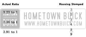
1956 Buick Rear Axle Gear Ratio Indications
Limits for Fitting and Adjusting
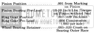
1956 Buick Limits for Fitting and Adjusting
6-2 DESCRIPTION OF REAR AXLE
The 1956 Buick rear axle assembly is of the semi-floating type in which the car weight is carried on the axle shafts through ball bearings enclosed in centerline of the pinion below the centerline of the ring gear. See figure 6-1.
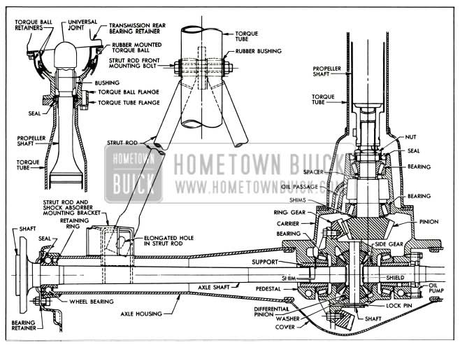
1956 Buick Rear Axle Assembly
The drive pinion is mounted in two tapered roller bearings which are pre-loaded by two selected spacers at assembly The pinion is positioned by shims located between a shoulder on the drive pinion and the rear bearing. The front bearing is held in place by a staked lock nut. The differential carrier casting has an oil feed passage to the pinion bearings and an oil return hole so that the oil will circulate and cool.
The differential is supported in the carrier by two tapered roller side bearings. These are pre-loaded by inserting shims between the bearings and the pedestals. The differential assembly is positioned for proper gear and pinion back-lash by varying these shims. The bearings are centered on the cross axis by lock taper cones secured in the pedestal bores by clamp bolts. The ring gear is bolted to the case. The case houses two side gears in mesh with two pinions mounted on a pinion axle which is anchored in the case by a spring pin. The pinions are backed by bronze spherical thrust washers.
The axle shaft inner splines engage the differential side gears with a floating fit. The outer ends are supported in the axle housing by thrust type ball bearings which also contain oil seals. The bearings are secured against a shoulder on the shaft by a press fit retainer ring. A retainer plate holds the bearings against shoulders in the housing. Wheel side thrust is taken at the wheel bearings, so an axle shaft may be removed simply by removing the bolts holding the retainer to the brake backing plate and axle housing flange.
The torque tube has an enlarged section at the rear which is bolted to the carrier behind the pinion bearings. This design prevents loads due to driving and braking forces from causing a deflection resulting in a bind between the pinion bearings.
The propeller shaft is full floating; it is splined at each end and is free to move endwise.
The coupling at the rear end is packed with grease at assembly. The splines are designed to permit a slight angular deflection.
The torque ball has two bonded rubber compression rings which act as a double rubber cushion between the ball and the inner and outer retainers. Normal rear axle movements are absorbed by flexing of the rubber without metal to metal contact, thereby cutting down on vibration and noise and providing a leak proof seal.
The strut rods are bolted to the torque tube bracket through rubber compression bushings. This eliminates metal to metal contact.
On 70 series cars only, a vane type oil pump is used to provide a jet of oil at the point where the ring and pinion mesh. This pump is mounted on the right carrier pedestal and is driven by a set of splines on the axle shaft. All axle and propeller shaft splines are of the fine pitch type. This tooth design reduces sliding friction and permits limited angular deflection without bind.
A seal mounted in the rear flange of the torque ball bears against a sleeve pressed on the front end of the propeller shaft to prevent transmission oil from passing into the torque tube. A seal in the front of the carrier bears against the pinion bearing nut to prevent differential gear oil from passing into the torque tube. Each wheel bearing has a built-in oil seal which allows gear oil to lubricate the bearing but prevents oil passage into the brake. See Figure 6-1.
6-3 REAR AXLE TROUBLE DIAGNOSIS
Elimination of External Noises
When a 1956 Buick rear axle is suspected of being noisy it is advisable to make a thorough test to determine whether the noise originates in the tires, road surface, front wheel bearings, engine, transmission, or rear axle assembly. Noise which originates in other places cannot be corrected by adjustment or replacement of parts in the 1956 Buick rear axle assembly.
- Road Noise. Some road surfaces, such as brick or rough surfaced concrete, cause noise which may be mistaken for tire or rear axle noise. Driving on a different type of road, such as smooth asphalt or dirt, will quickly show whether the road surface is the cause of the noise. Road noise usually is the same on drive or coast.
- Tire Noise. Tire noise may easily be mistaken for rear axle noise even though the noisy tires may be located in the front wheels. Tires worn unevenly or which have the surfaces of the non-skid divisions worn in sawtooth fashion are usually noisy, and may produce vibrations which seem to originate elsewhere in the vehicle. This is particularly true with low tire pressure. Some designs of non-skid treads may be more noisy than others, even when tires are new.
- Test for Tire Noise. Tire noise changes with different road surfaces but rear axle noise does not. Temporarily inflating all tires to approximately 40 pounds pressure, for test purposes only, will materially alter noise caused by tires, but will not affect noise caused by the rear axle. Rear axle noise usually ceases when coasting at speeds under 30 miles per hour; however, tire noise continues but with lower tone as car speed is reduced. Rear axle noise usually changes when comparing “pull” and “coast”, but tire noise remains about the same.
- Front Wheel Bearing Noise. Loose or rough front wheel bearings will cause noise which may be confused with rear axle noises; however, front wheel bearing noise does not change when comparing “pull” and “coast.” Light application of brake while holding car speed steady will often cause wheel bearing noise to diminish as this takes some weight off the bearing. Front wheel bearings may be easily checked for noise by jacking up the wheels and spinning them, also by shaking wheels to determine if bearings are loose.
- Engine and Transmission Noises. Sometimes a noise which seems to originate in the rear axle is actually caused by the engine or transmission. To determine which unit is actually causing the noise, observe approximate car speeds and conditions under which the noise is most pronounced, then stop the car in a quiet place to avoid interfering noises. With transmission in neutral, run engine slowly up and down through engine speeds corresponding to car speed at which the noise was most pronounced. If a similar noise is produced with car standing, it is caused by the engine or transmission, and not the rear axle.
Rear Axle. Noises
If a careful test of the car shows that the noise is not caused by external items as described in subparagraph a, it is then reasonable to assume that the noise is caused by the 1956 Buick rear axle assembly. The rear axle should be tested on a smooth level road to avoid road noise. It is not advisable to test rear axle for noise by running with the rear wheels jacked up.
Noises in the 1956 Buick rear axle assembly may be caused by faulty rear wheel bearings, faulty differential or pinion shaft bearings, differential side gears and pinions worn, or by a mismatched, improperly adjusted or scored ring and pinion gear set.
- Rear Wheel Bearing Noise. A rough rear wheel bearing produces a vibration or growl which continues with car coasting with transmission in neutral. A brinnelled rear wheel bearing causes a knock or click approximately every two revolutions of rear wheel since the bearing rollers do not travel at the same speed as the rear axle and wheel. With rear wheels jacked up, spin rear wheels by hand while listening at hubs for evidence of rough or brinnelled wheel bearings.
- Differential Side Gear and Pinion Noise.
- Differential side gears and pinions seldom cause noise since their movement is relatively slight on straight ahead driving. Noise produced by these gears will be most pronounced on turns.
- Pinion Bearing Noise. Rough or brinnelled pinion bearings produce a continuous low pitch whirring or scraping noise starting at relatively low speed.
- Ring and Pinion Gear Noise. Noise produced by the ring and pinion gear set generally shows up as drive noise, coast noise or float noise.
- Drive noise is most evident on constant acceleration through the speed range.
- Coast noise is most evident when car is allowed to coast through the speed range with throttle closed.
- Float noise is most evident while just barely holding the car speed constant on a level road at any speed.
- Drive, coast and float noises will be very rough and irregular if the differential or pinion shaft bearings are rough, worn, or loose, and will vary in tone with speed.
Check for Propeller Shaft Vibration
Objectionable vibrations at high speed (65 m.p.h. or higher) may be caused by a propeller shaft that is out of balance. Out of balance may be due to a bent shaft.
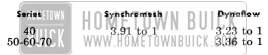
To determine whether the propeller shaft is causing vibration, drive car through the speed range and note car speed at which vibration is most pronounced. Shift transmission into second gear (synchromesh) or low range (Dynaflow) and drive car at same engine speed as when vibration was most pronounced in direct drive, and note the effect on vibration.
To determine the required engine speed, divide car speed by the transmission gear ratio, using 1.6 for synchromesh or 1.8 for Dynaflow. Example: If vibration is most pronounced at 65 m.p.h. in direct drive, the same engine speed would be produced in
Second gear (synchromesh) at 65/1.6 = 40 m.p.h.
or in low range (Dynaflow) at 65/1.8 = 36 m.p.h.
If the vibration is still present at the same engine speed whether in direct drive or in the lower gear, then the propeller shaft is not out of balance. If the vibration decreases or is eliminated in the lower gear then the propeller shaft is out of balance and should be removed for correction.
Oil Leaks
It is difficult to determine the source of some oil leaks. When there is evidence of an oil leak at these locations, the probable cause is as follows:
- Oil coming from the drain hole shield under the axle housing at the brake backing plate is caused by either a leaking wheel bearing seal or a leaking wheel bearing inner gasket. A leaking inner gasket is generally the result of end-play of the wheel bearing in the axle housing. The wheel bearing must be held tight against the inner gasket to keep oil from leaking out between the bearing outer race and axle housing. See paragraphs 6-6, (c) for correct adjustment.
- Oil coming from between the rear flange of the torque tube and the carrier is caused by either a leaking pinion seal or a leaking propeller shaft seal. The torque tube is normally dry so no gasket is used between the rear flange and the carrier. In a Dynaflow equipped car, leakage of light oil at this point is caused by a defective propeller shaft seal; leakage of heavy oil is caused by a defective pinion seal.
6-4 REMOVAL AND INSTALLATION OF 1956 BUICK REAR AXLE ASSEMBLY
It is not necessary to remove the 1956 Buick rear axle assembly for repair or replacement of a strut rod, an axle shaft, a wheel bearing, or a wheel bearing seal; however, the 1956 Buick rear axle assembly should be removed for any other repairs.
Removal of 1956 Buick Rear Axle Assembly
- Place car stands solidly under frame so that rear end of car is high enough to permit working underneath and place a floor jack under center of axle housing so it just supports weight of 1956 Buick rear axle assembly.
- Disconnect radius rod at axle end.
- Disconnect lower ends of rear springs.
- Disconnect lower ends of rear shock absorbers.
- Disconnect parking brake cable at rear cable sheave and at bracket on torque tube.
- Disconnect brake hose from pipe at frame X member and remove yoke. Cover hose and brake pipe openings to prevent entrance of dirt.
- Loosen torque ball retainer bolts so ball is free. Remove two opposite torque tube flange bolts, replacing them with two 3″ guide pins. Remove other flange bolts. See Figure 6-2.

1956 Buick Removing Torque Tube from Torque Ball
Installation of 1956 Buick Rear Axle Assembly
- Check torque ball for evidence of oil leaking and for wear of universal joint bushing. If torque ball needs repair or replacement, see paragraph 4-12.
- Check propeller shaft seal for oil leaks or damage. Install a new seal if necessary. Use a new torque tube front flange gasket.
- Rest car solidly on stands placed under frame, with rear end of car high enough to permit working underneath. Roll rear axle assembly under car.
- Carefully move axle assembly into place, guiding propeller shaft and torque tube into proper alignment with torque ball using two 3″ guide pins to avoid damage to propeller shaft seal. Rotate rear wheel to line-up propeller shaft and universal joint splines.
- Connect torque tube to torque ball, tightening bolts to 30-35 ft. lbs. Do not tighten torque ball retainer bolts at this time.
- Connect rear springs to rear axle assembly. Connect shock absorber lower ends loosely.
- Connect brake hose to brake pipe at frame X member and lock in place with yoke. Connect parking brake cable through bracket on torque tube and to brake cable sheave. Bleed rear wheel cylinders and adjust parking brake as described in paragraphs 9-7 and 9-9.
- Connect radius rod loosely to rear axle.
- Lower car on wheel stands. Then tighten torque ball retainer bolts, shock absorber lower ends, and radius rod lower end.
NOTE: Normal weight must be on rear wheels when tightening these parts so that rubber bushings will be clamped in neutral position. - Lower car to floor. Fill axle housing to filler plug hole using approved gear lubricant.
6-5 REPLACEMENT OF REAR AXLE STRUT ROD
The rear ends of the strut rods are attached to the axle housing by nuts. The front ends of both strut rods are bolted through rubber compression bushings to a bracket welded on the torque tube. Strut rods may be replaced without removing rear axle assembly.
CAUTION: When a strut rod is damaged, there is a good possibility that the rear axle housing is sprung.
6-6 REPLACEMENT OF AXLE SHAFT, WHEEL BEARING, OR OIL SEAL
Removal of Axle Shaft Assembly
- Place car stands solidly under rear axle housing so that wheels are clear of floor.
- Remove rear wheel and brake drum.
- Remove nuts holding wheel bearing retainer plate to brake backing plate, leaving bolts in place to support backing plate.
- Pull out axle assembly using Puller J-6176 with a slide hammer. Be careful not to disturb brake backing plate. See Figure 6-3.
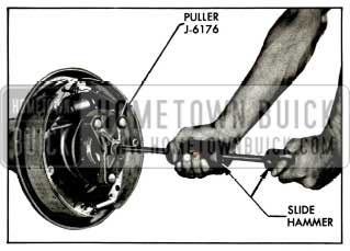
1956 Buick Removing Rear Axle Shaft
Replacement of Wheel Bearing or Oil Seal
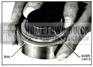
The oil seal is located on the outer side of the bearing between the inner and outer races of the wheel bearing.
- Nick the wheel bearing retaining ring. NOTE: The ring need not be completely split, but nicked deep enough in 3 or 4 places to spread it. Retaining ring will then slip off with light pressure. See Figure 6-4.
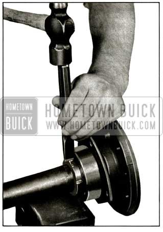
1956 Buick Removing Rear Wheel Bearing Retaining Ring
1956 Buick Removing Rear Wheel Bearing
1956 Buick Installing Rear Wheel Bearing Oil Seal
1956 Buick Installing Rear Wheel Bearing or Retaining Ring
NOTE: Bearing retainer plate must be on axle shaft before bearing is installed.
Then press retaining ring against bearing with chamfer toward bearing.
Installation of Axle Shaft
Rear axle shafts are not interchangeable between sides; the right shaft is longer than the left and has an extra set of splines for driving the oil pump.
- Install new gasket at bearing shoulder in housing. See Figure 6-8.
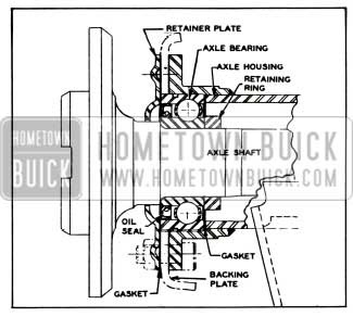
1956 Buick Axle Shaft and Bearing Assembly
6-7 REMOVAL OF TORQUE TUBE, PROPELLER SHAFT, AND CARRIER ASSEMBLY
Removal of Torque Tube and Propeller Shaft
- Remove rear axle assembly from car (par. 6-4).
- Place axle assembly on suitable stands. See figure 6-9.
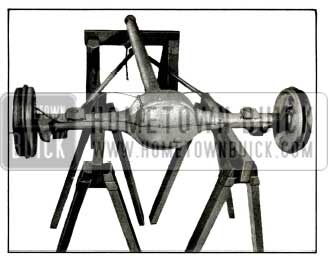
1956 Buick Placing Rear Axle Assembly on Stands
CAUTION: The strut Tods are easily bent while disconnected from the torque tube.
Removal of Carrier Assembly
- Remove rear axle assembly from car (par. 6-4).
- Place axle assembly on suitable stands and remove torque tube and propeller shaft as described in par. 6-7, (a).
- Remove brake line from rear axle housing to avoid damaging it later.
- Remove both axle shaft assemblies (par. 6-6).
- Rotate axle housing so carrier is upward.
- Remove carrier to axle housing nuts and lift carrier from housing using Sling J-6247 and a chain hoist, if available. See Figure 6-10
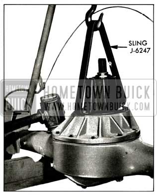
1956 Buick Removing Carrier Assembly from Rear Axle Housing
6-8 CLEANING AND INSPECTION OF REAR AXLE PARTS
Cleaning Rear Axle Parts
Hypoid lubricant combines readily with water and even a small amount of water has a deteriorating effect on the lubricant. For this reason steam or water should not be used for cleaning rear axle parts.
Gasoline, kerosene, or other solvents are satisfactory for cleaning parts when removed from rear axle housing, if parts are thoroughly dried before installation. No solvent should be used in an assembled rear axle, however, because if all traces of the cleaner are not removed, the fresh lubricant will be contaminated. If the rear axle needs cleaning, it must be removed from the car and disassembled.
Wash all disassembled parts in clean solvent and wipe with clean, dry cloths. Vapor degreasers must not be used on painted parts, seals or bearings. Finish drying with clean dry air blast. Do not spin bearings.
Inspection of Rear Axle Parts
- Thoroughly inspect rear wheel bearing for rust, binding, or excessive looseness as shown under Bearing Service (par. 1-10).
- Propeller Shaft. Check for wear of splines. Splines must be a snug slip fit when assembled. These splines are designed to give slight angular freedom but must not have excessive backlash.
- Rear Axle Housing and Torque Tube. A sprung housing or torque tube should be replaced; straightening is not recommended. These parts must never be heated with a torch for straightening as this may produce distortion of machined bores of soft spots in the metal in which fatigue and breakage may develop in service. Inspect carefully for cracks, especially at welds.
6-9 INSTALLATION OF CARRIER ASSEMBLY, PROPELLER SHAFT AND TORQUE TUBE
Installation of Carrier Assembly
Before installing the carrier assembly, the carrier and axle housing mounting surfaces must be clean and free of any old gasket material. Also, make sure these surfaces are free of any burrs or nicks.
- Rotate axle housing so that carrier mounting surface is upward and install a new carrier gasket.
- Install carrier assembly in axle housing using Sling J-6247 as shown in figure 6-10. Install nuts and tighten them evenly and alternately to 50-60 ft. lbs.
- Install brake line on rear axle housing.
- Install both axle shaft assemblies (par. 6-6).
Checking Propeller Shaft
The propeller shaft now used is free to float on the pinion splines. If the propeller shaft is handled carefully during removal and installation, it will not normally be necessary to perform a dial indicator check for straightness.
However, if there is a noise or vibration at high speeds which might be caused by a bent shaft (par. 6-3, C), or if there is any possibility that the shaft has been damaged due to rough handling or collision, the propeller shaft should be checked for straightness as follows:
- Support propeller shaft on V-blocks placed under the seal sleeve at “A” and under the coupling at “B.” See figure 6-11.
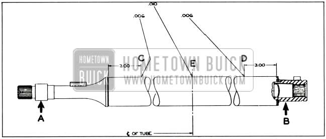
1956 Buick Propeller Shaft Run-Out Specifications
NOTE: If the propeller shaft is turned rapidly, it is easier to ignore any surface imperfections and to properly locate the high center of a bent propeller shaft.
- If run-out exceeds specifications due to a bent propeller shaft, it is probably more economical to replace the shaft than to attempt straightening it. However, if it is decided to straighten the shaft, mark points of greatest run-out along the length of the tube. By studying these high center marks, the general type and extent of the bend may be readily seen and the straightening procedure planned accordingly.
Straightening Propeller Shaft
In order to straighten a propeller shaft, the following tools are necessary: an arbor press, a bending block and two support blocks which are shaped to conform to the tube, and a support which conforms to the seal sleeve shape. This straightening set-up should be near the checking set-up because the shaft must be rechecked after every bend.
The method used in straightening depends on the type of bend. In general, pressure should be applied at the high center of the bend with the shaft supported at both ends of the bend. Then by checking and bending repeatedly, the high center can be brought down until the indicator reading at this point is approximately the same as that at a point 180 degrees opposite. When bending the shaft, use steady pressure and not shock blows to spring the shaft.
Installation of Propeller Shaft
- Check propeller shaft and pinion splines for excessive wear. Remove any nicks or burrs. Replace propeller shaft seal sleeve if scored or grooved. Inspect propeller shaft rear packing and retainer and replace if worn or damaged.
- Pack rear propeller shaft coupling with heavy wheel bearing grease (Buick Spec. #555) bringing level to inner end of the splines.
- Slide propeller shaft on splines of pinion.
Installation of Torque Tube
Before installing the torque tube, flanges on both ends must be free of burrs or nicks. Also, check the torque tube mounting surface on the carrier.
- Slide torque tube over propeller shaft being careful to keep torque tube centered on propeller shaft to avoid side thrust.
CAUTION: Propeller shaft will bend easily if side pressure is put on it.
- Position torque tube with strut rod bracket downward, being careful not to damage brake line. Install torque tube to carrier bolts and tighten alternately to 50-60ft. lbs.
NOTE: No gasket is used between the torque tube and carrier.
- Connect brake line at tee on rear axle housing. Connect strut rods and tighten bolt to 85-100 ft. lbs.
- Install rear axle assembly in car. (par. 6-4).
6-10 DISASSEMBLY OF CARRIER ASSEMBLY
Removal and Disassembly of Ring Gear and Case Assembly
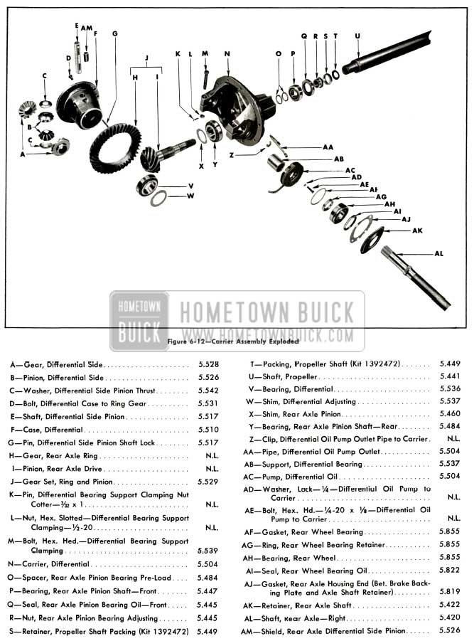
1956 Buick Carrier Assembly Exploded
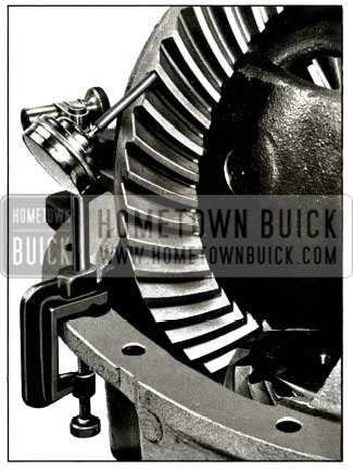
- Place carrier assembly in suitable mounting fixture such as Fixture J-6177. See Figure 6-13.
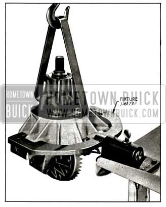
1956 Buick Placing Carrier in Holding Fixture
CAUTION: Do not use excessive force on wedges or pedestal bores may be permanently distorted.
- Pull differential bearing supports using Puller J-6199 and a slide hammer puller. See Figure 6-14.
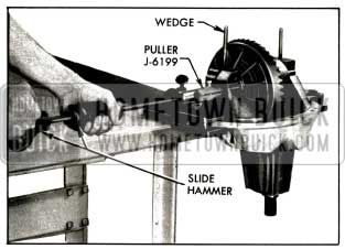
1956 Buick Removing Differential Bearing Supports
CAUTION: Do not spread pedestals any farther than necessary or they may be permanently sprung.
Lift case straight out until side bearings are half-way clear of pedestals. Then take hold at bearings with both hands to keep them from dropping and lift case assembly out. Keep right and left bearings, shims and supports in sets so that they may be reinstalled in their same positions. Remove spreader tool.
- Mark ring gear and case, so they may be reassembled in same relative position. Remove ring gear.
- Drive differential pinion axle spring pin, pinion axle and pinion shield from case. Mark side gears, pinions, and washers so they may be reinstalled in same sides. Remove side gears, pinions, and spherical washers.
- If a differential bearing is to be replaced, pull bearing outer race from case using Remover J-6269. See figure 6-15.
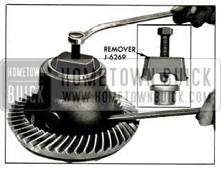
1956 Buick Removing Differential Bearing Outer Race
Removal of Pinion and Bearings
- Check pinion pre-load as described in paragraph 6-11. This will show up excessive bearing wear or an error in pre-load setting.
- It is advisable to check the pinion depth setting as described in paragraph 6-11. This will show up any error in the existing setting and will also enable used parts to be reinstalled at original setting to avoid changing gear tooth contact.
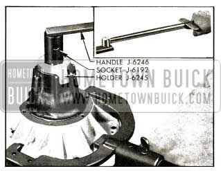
- Cut out and drive up staked section of pinion bearing lock nut with cape chisel, being careful not to damage threads on pinion. Hold pinion nut to carrier with Holder J-6245 and turn pinion clockwise through nut using socket J-6192 and Handle J-6246. See figure 6-16.
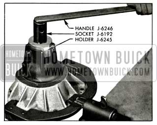
1956 Buick Removing Pinion Nut
1956 Buick Removing Rear Pinion Bearing
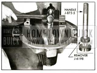
1956 Buick Removing Front Pinion Bearing Outer Race
NOTE: The remover must be inserted in carrier before the driver handle is screwed into it. See figure 6-19.
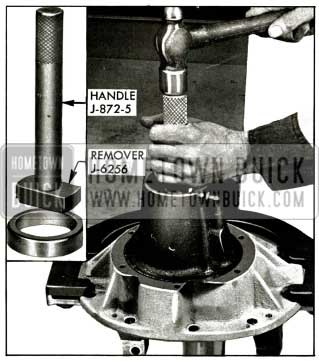
1956 Buick Removing Rear Pinion Bearing Outer Race
6-11 ASSEMBLY OF CARRIER ASSEMBLY
Installation of Pinion and Bearings
Before installation of pinion and bearings make certain that interior of carrier housing is absolutely clean and dry. Al so make certain that parts to be assembled are clean and that pinion bearing shims are not burred. Bearings and oil seals should be lightly lubricated with rear axle lubricant just before assembly.
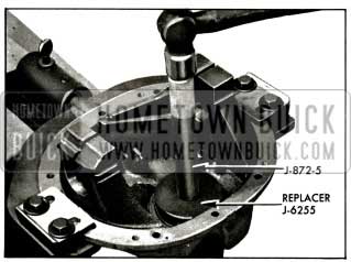
- Drive front pinion bearing outer race against shoulder in carrier using Replaced J-6197 with driver handle. See figure 6-20.
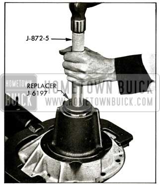
1956 Buick Installing Front Pinion Bearing Outer lace
1956 Buick Installing Rear Pinion Bearing Outer Race
1956 Buick Installing Rear Pinion Bearing
1956 Buick Tightening Pinion Nut
1956 Buick Checking Pinion Bearing Pre-Load
If pre-load is under 10 inch pounds, replace spacer with a thinner one; if pre-load is over 30 inch pounds, remove pinion nut and front bearing and replace pre-load spacer with a thicker one. These spacers are furnished to be used in pairs so that possible thicknesses range from .400″ to .470” by thousandths. Service spacers are marked with their thickness in thousandths.
If pre-load is over 30 inch pounds, the approximate number of thousandths to be added to spacer thickness may be determined from the chart in Figure 6-25.
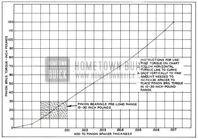
1956 Buick Chart for Correcting Excess Pinion Pre-Load
Pinion Setting Marks and Setting Gauges.
All Buick ring and pinion gear sets are selectively matched for best operating position and proper tooth contact. After matching, a serial number is etched on one tooth of pinion and on rear face of gear to aid in keeping matched parts together. See Figure 6-26. Parts having different serial numbers must never be used together.
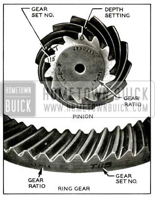
1956 Buick Ring and Pinion Gear Set Markings
Ring and pinion gear sets are matched in a special test machine which permits adjustment of pinion depth in ring gear until a point is reached where best operation and proper tooth contact under load is obtained. At this point, the setting of the pinion with reference to the centerline of the ring gear is indicated by the machine. This setting may vary slightly from the design or “nominal” setting due to allowable variation in machining the parts.
This variation in thousandths of an inch over or under the “nominal” setting is etched on the small end of a pinion tooth. See figure 6-26.
When a pinion is marked “+” (plus) it means that the rear face of the pinion when pressed in the carrier must be at the “nominal” distance from the centerline of the side bearing pedestals plus the amount indicated on the pinion tooth. When a pinion is marked “-” (minus) it means that it must be located at the “nominal” distance minus the amount indicated on the pinion tooth.
The dial indicator type Pinion Setting Gauge J-5647 is used with adapters to provide a fast and accurate method of checking pinion location; it gives a direct reading on a dial indicator that does not require computation or reference tables. See figure 6-27.
Before checking the pinion setting, pinion bearing pre-load must be right because incorrect pre-load will cause a false pinion depth reading.
Checking Pinion Setting
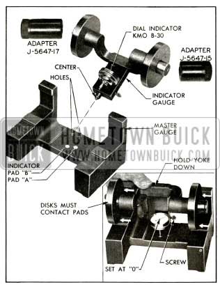
Pinion Setting Gauge J-5647 consists of a “master gauge” and an “indicator gauge” upon which Dial Indicator KM0-30-B is mounted. Adapters J-5647-17 are not used when “zeroing the gauge,” but are used in place of the discs when checking the pinion setting. See figure 6-27.
1956 Buick Pinion Setting Gauge J-5647 and Adapters
- Make certain that the gauge parts are clean, particularly the center and discs of indicator gauge, the centering holes, indicator pads, disc pads on the master gauge, and the adapter holes and outer surfaces.
- Install the discs on the “indicator gauge” and install the small contact button on the stem of Dial Indicator KM0-30-B. Mount the dial indicator on the indicator gauge. See figure 6-27.
- Place indicator gauge on the master gauge so that the spring loaded center is engaged in the centering hole corresponding to the indicator pad “B,” which is used for any of the following gear ratios stamped on pinion: 43-11 (3.9 to 1), 43-12 (3.6 to 1), 47-14 (3.36 to 1), 42-13 (3.2to1).
NOTE: Pad “A” is used for certain prior model gear ratios.
- Center the indicator contact button on the specified indicator pad and lock the indicator by tightening the thumb screw.
- Hold yoke down firmly, with both discs contacting the horizontal and vertical pads on master gauge, and set the dial indicator at zero (“0”).
- Make sure that differential bearing support bores are free of burrs and that the center of the pinion is clean.
- Rotate the pinion until the blank tooth between the matching number and the pinion setting mark is slightly counter clockwise of top center (at about 11 o’clock). This tooth is called the gauging tooth (Fig. 6-26) because it is used for locating and gauging during production and should therefore be used for gauging in service.
- Drive a wedge into each pedestal split and spread them just enough so that an Adapter J-5647-17 will slip in. Then place the indicator gauge in the carrier as follows: (sea figure 6-28)
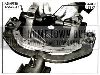
1956 Buick Checking Pinion Setting
- Remove discs from indicator gauge and hold it in position in the carrier with pins centered in the pedestal bores.
- Slide long adapter thro11gh pedestal bore farthest from pinion and over gauge pin. Then slide short adapter in place on other side.
- Be sure that gauge center is engaged in pinion center and that adapters are against shoulders of gauge. Then remove pedestal wedges.
- Turn pinion if necessary so that indicator contact button has a good contact with gauging tooth of pinion.
CAUTION: This reading does not indicate the thickness of the shim to be used, but only indicates the variation from the “nominal” setting of the gauging face of this pinion.
- Recheck indicator “zero setting” on master gauge with discs to make sure it was not changed in handling.
- If the old ring and pinion gear set is being reinstalled and it has been in use long enough to establish a wear pattern on teeth, the original pinion setting found before removal should be maintained to avoid changing tooth contact.
- If the ring and pinion set is new, or has not been in use long enough to establish a wear pattern on teeth, the dial indicator reading should be within .001″ of the pinion setting marked on pinion.
- If pinion setting is not as specified, adjust as follows:
Adjustment of Pinion Position
The pinion setting is adjusted by changing the thickness of the shim which is located between the rear pinion bearing inner race and the head of the pinion. These shims are furnished in thicknesses ranging from .040″ to .056″ by thousandths.
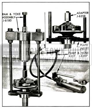
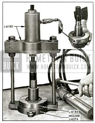
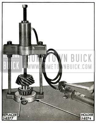
- Remove pinion assembly and press off rear pinion bearing using Remover J-6184 and Holder J-6274. (Par. 6-10, b).
- Remove shim from pinion, wipe dry and measure its thickness with a micrometer. Service shims are marked with their thickness in thousandths. Measure shim anyway, however, as any slight error here will necessitate pulling pinion and bearing again.
- Increase or decrease thickness of shim as required to obtain proper pinion setting.
If pinion is marked “+8”, but gauge reads “+6″, decrease thickness of shim by .002”. If gauge reads “+ 10″, increase thickness of shim by .002”.
If pinion is marked “-8”, but gauge reads “-6″, increase the thickness of shim by .002”. If gauge reads “-10″, decrease thickness of shim by .002”.
CAUTION: Whenever a new pinion is to be installed, its depth setting must be gauged. Even though the new pinion has the same depth marking, it may require a different thickness shim because the dimension from the gauging face to the bearing shoulder varies in different pinions.
- Change pre-load spacers by same amount that shim thickness was changed. If thickness of shim was decreased .002″, use spacers with .002″ less thickness. If thickness of shim was increased .002″, use spacers measuring .002″ thicker.
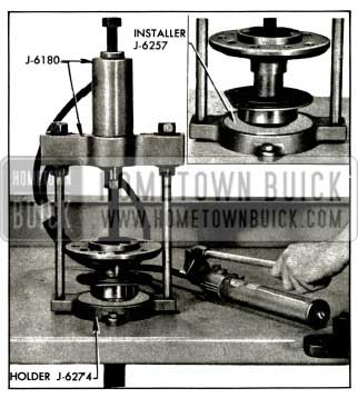
- Reinstall rear pinion bearing on pinion with new thickness shim. (Par. 6-11, a.)
- Lubricate new pinion seal with axle lubricant and install with lip toward bearing, using Installer J-6200. See Figure 6-29.
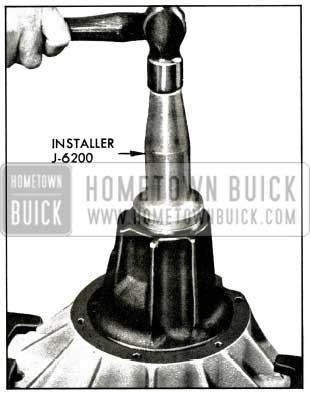
1956 Buick Installing Pinion Seal
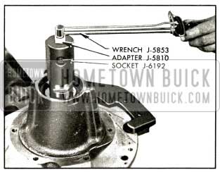
Reinstall pinion and bearings carefully in carrier with new thickness pre-load spacers. Install pinion nut and tighten to 80 foot pounds as shown in figure 6-23.
Assembly of Differential Case, Gears and Bearings
- Drive differential bearing outer races into case, using Replacer J-6263. See figure 6-30.
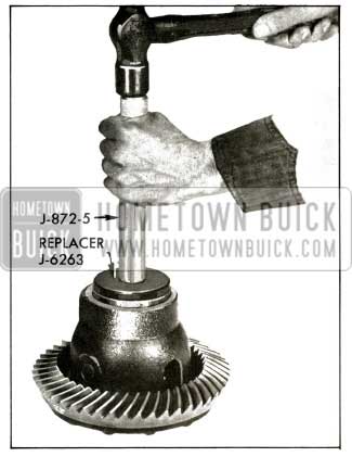
1956 Buick Installing Differential Bearing Outer Race
- Install side gears, pinions, and spherical washers in case. There are no fiat washers behind side gears. If same parts are used, replace in original sides. Install pinion shield and pinion axle. Drive spring pin through hole in pinion axle until flush with case.
- Check matching numbers on ring gear and pinion to make sure the two parts have not been mixed with another gear set. See figure 6-26.
- After making sure that mating surfaces of case and ring gear are clean and free of burrs, bolt ring gear to case using three Studs J-6251 to align parts. See figure 6-31.
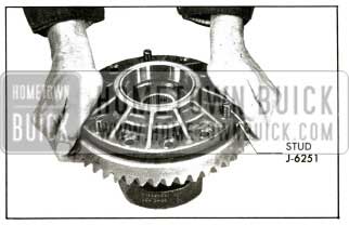
1956 Buick Installing Ring Gear on Differential Case
If same ring gear and case are used, line up marks so they are assembled in same relative positions. Do not use lock washers or any substitute bolts.
Installation and Adjustment of Ring Gear and Case Assembly
- Before installation of ring gear and case assembly make sure that differential bearing and bearing support surfaces in carrier pedestals are clean and free of burrs. Remove any burrs which might prevent bearings or bearing supports from seating properly.
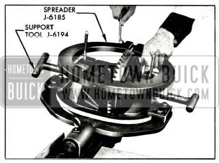
- Place case assembly and differential bearings in position in carrier. If same bearings are used, replace in original positions. Insert Support Tools J-6194 through the pedestal bores into the bearing inner races. Press tools toward each other to seat them, using hand pressure. If support tools are loose, install pedestal clamp bolts and nuts and tighten lightly until support tools can just be moved by twisting them. If support tools are too tight, loosen them as necessary by slightly wedging pedestals open with chisels. See figure 6-32.
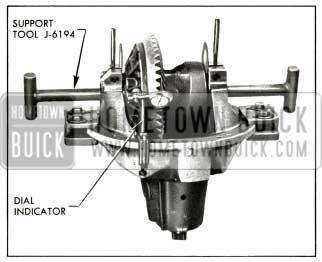
1956 Buick Positioning Differential for Correct Backlash
- Mount dial indicator as shown in figure 6-33.
1956 Buick Checking Backlash with Dial Indicator
Use a small button on indicator stem so that contact can be made near heel end of tooth. Set dial indicator so that indicator stem is as nearly as possible in line with gear rotation and perpendicular to the tooth surface.
If stem bears against edge of tooth, or stem is at considerable angle to the line of gear rotation, or at a considerable angle to face of the tooth, a false indication of backlash will be obtained.
CAUTION: Any gear lash check must be made with pinion locked to carrier to be sure it cannot turn.
CAUTION: Do not spread pedestals any farther apart than is absolutely necessary to push differential shim into position. If pedestals are sprung too far, they may take a permanent set. See figure 6-34.
1956 Buick Installing Differential Bearing Shims
Leave support tool in position until after shim is started to keep case assembly from dropping out of line.
- Remove left assembly tool and push shim into final position. Center it first with fingers through pedestal bore, then with a support tool. Remove spreader tool and pedestal wedges.
- Drive each differential bearing support into its pedestal until seated solidly in the bearing, using Support Tool J-6194. See figure 6-35.
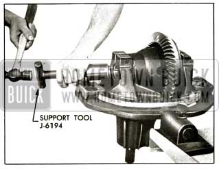
1956 Buick Installing Differential Bearing Supports
Tighten pedestal clamp bolts and nuts to 30-40 foot pounds. Secure nuts with cotter pins.
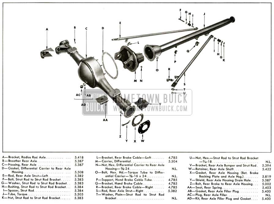
1956 Buick Rear Axle Exploded View
Hello: I have a 1956 Buick Special in my mechanic’s shop for repair of the differential, and he does not have a differential case spreader for it. Do you have any suggestions as to where I could borrow or buy such a tool so he can complete the repair. Thank you very much.