SECTION 10-A ELECTRICAL SPECIFICATIONS
10-1 BATTERY SPECIFICATIONS
1956 Buick Battery Specifications
10-2 GENERATING SYSTEM SPECIFICATIONS
- Generator
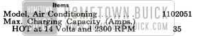
1956 Buick Generator Specifications
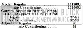
1956 Buick Generator Regulator Specifications
10-3 CRANKING (STARTER) SYSTEM SPECIFICATIONS
1956 Buick Cranking Specifications
10-4 IGNITION SYSTEM SPECIFICATIONS
- Ignition Coil
1956 Buick Iginition System Specifications
1956 Buick Spark Plugs Specifications
1956 Buick Distributor Specifications
10-5 LIGHTING SYSTEM SPECIFICATIONS
- Lighting and Other Circuit Fuses
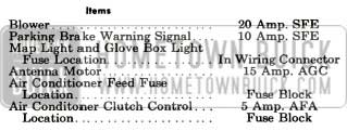
1956 Buick Lighting System Specifications
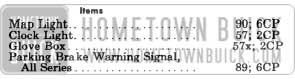
1956 Buick Lamp Bulbs
10-6 SIGNAL SYSTEMS SPECIFICATIONS
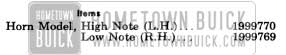
1956 Buick Signal Systems Specifications
SECTION 10-B BATTERY
10-7 BATTERY
A new Delco-Remy battery, model 3 KMR 62, is used in all 1956 series. The battery is warranted for 36 months on a pro-rata basis in passenger car service regardless of mileage. The new warranty is made possible by the use of a new grid alloy and microporous rubber separators. These two features combined nearly double the overcharge life, significantly increase average life, and increase both the 150 ampere discharge time and the 5 second voltage characteristic. This means improved cranking ability in addition to longevity.
SECTION 10-C GENERATING SYSTEM
10-8 GENERATOR REGULATOR
A new generator regulator is used on all 1956 series. The unit has the cover screws on the side of the assembly nearer the sealing surface to provide a more positive seal and I greater protection against dust and moisture I damage. This feature will reduce points oxidation within the unit. To distinguish between the air conditioning regulator and the conventional regulator, the air conditioning model will be stamped with the number 1119002, and the conventional regulator will be stamped with the number 1119003.
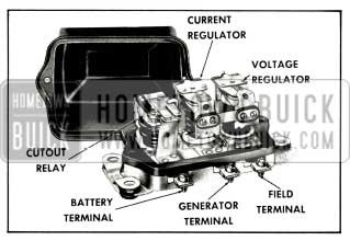
1956 Buick Generator Regulator
The wiring circuit through the regulator has been slightly changed to gain better regulation of the generator system and extended life to the unit. However, this change does not affect service procedures. See figure 10-2.
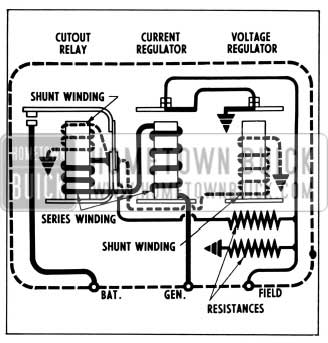
1956 Buick Generator Regulator Circuit Diagrams
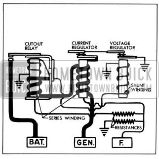
1956 Buick Generator Regulator Circuit Diagram
The 1956 unit has a copper plated armature on the current regulator which was previously cadmium plated. While this changes appearance and provides superior operating characteristics, service procedures are unchanged. All specifications and adjustments remain the same in 1956 and the new unit is interchangeable with units used on 1955 model cars.
10-9 AIR CONDITIONING GENERATOR
The generator used on air conditioned jobs will have a maximum output of 35 amperes at a HOT engine speed of 2300 RPM.
SECTION 10-D IGNITION SYSTEM
10- 10 IGNITION DISTRIBUTOR
One minor but important change has taken place in the 1956 distributor. The distributor drive gear is now being made of cast iron alloy. The 1956 distributor cannot be used in previous year’s V-8 engines and the 1955 distributor cannot be used in the 1956 engines. The primary reason for this is that the 1955 forged steel camshaft is not compatible with the 1956 cast iron alloy distributor drive gear. Also, the 1956 cast iron alloy camshaft is not compatible with the 1955 steel distributor drive gear.
SECTION 10-E LIGHTING SYSTEM
10-11 LICENSE LAMP
All series will have a single license lamp concealed in the center of the rear bumper upper rail.
10-12 HEADLIGHT JUNCTION BLOCK
A different headlight junction block is used in all series for 1956. The new block is a plug and socket arrangement with the plug leading from the headlight and horn. The socket is mounted by a spring clip in the front fender skirt, upper. This is the same location as that of the headlight wiring harness grommet in 1955 models. The socket has five divisions; each painted a different color. The socket plug is made up of five separate wires color-coded to coincide with the socket colors.
This new junction block eliminates the screw type terminals used in previous years.
10-13 NEW GUIDE HEADLIGHT AIMER
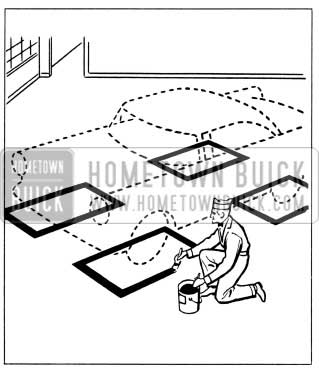
The Guide T-3 Safety-Aimer makes it possible to precision-aim Guide T-3 headlamps in a minimum amount of time. No screens or other aiming equipment are needed and aiming can be accomplished in daylight or darkness without the headlights turned on. Floor space requirements are cut considerably since only enough room is needed for a man to walk around the car. T-3 Safety-Aimer comes from the factory with the level bubbles accurately set. Pads on its base make it possible for it to be used as a level to check any given area.
Mounting Headlight Aimer
- Drive the car onto the selected aiming area. (Unlevel floors are covered in detail in paragraphs d and e.)
- Remove the headlight doors and install a set of Guide T-3 headlights if necessary.
(NOTE: Only Guide T-3 headlights can be used with the Safety-Aimer.)
- Mount the aimers on each headlamp so that points engage smooth inner ring of aimer. Be sure to mount left hand aimer (with string) first. See Figure 10-4.
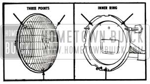
1956 Buick Headlight Almer
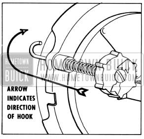
1956 Buick Headlight Hook
1956 Buick Headlight Adjustment
Horizontal Aim
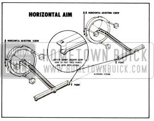
- Adjust left headlamp by turning horizontal adjusting screw AA in or out to make string first touch point G. See figure 10-7.
1956 Buick Headlight Horizontal Aim
- Repeat operation on the other headlamp by moving horizontal adjusting screw in or out to make string touch point F. See figure 10-7.
- Recheck points F and G. If necessary, make slight adjustments to have string barely touch points F and G.
Vertical Aim
- Center bubble by turning vertical adjusting screw B. (To insure proper location, back screw out until bubble is at end of vial. Then turn screw clockwise to center bubble.) See figure 10-8.
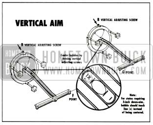
1956 Buick Headlight Vertical Aim
- Repeat the same operation on the other headlamp.
- Recheck the string at points F and G and be sure bubbles are centered.
- Remove aimers and replace headlight doors. The headlights are now precision-aimed.
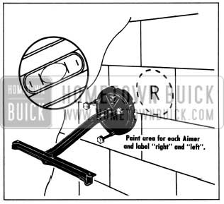
Selecting a Level Aiming Area
If available, a wheel-alignment ramp or any other level surface is best. If not, select an area believed to be level.
- Drive a car onto the selected surface and install the T-3 aimer on both headlamps.
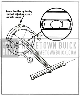
- Turn vertical lamp adjustment screw to center level bubbles. See figure 10-9.
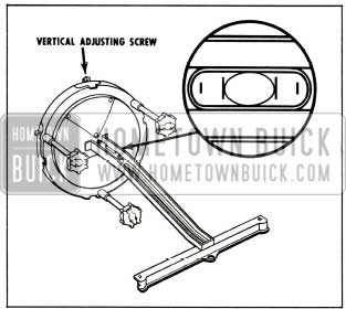
1956 Buick Headlight Vertical Adjustment
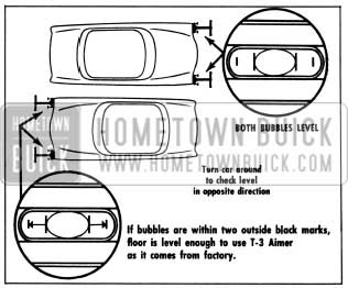
1956 Buick Headlight Levelling
If either bubble moves beyond the outside black marks on the vial, there is too much slant to the floor. In this event a level position may be found by driving the car onto the aiming area at different angles. See Figure 10-11.
1956 Buick Headlight Aiming Angles
1956 Buick Headlight Aiming Areas
1956 Buick Headlight Adjusting Screws
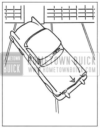
Compensating for an Unlevel Floor
If the floor is not level within the limits specified, the T-3 Aimer can be adjusted to compensate for the error in the floor.
- Drive car onto a surface that is known to be level such as a wheel alignment ramp.
- Install T-3 aimers on both lamps and level bubble by adjusting vertical adjusting screws.
- Remove the aimers from the headlamps (leaving the doors off) and return the car to the aiming area which will be used.
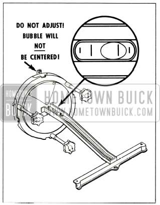
- Reinstall T-3 aimers on headlamps but do not touch vertical adjusting screws on lamp frame.
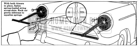
- Rock car sideways to equalize the springs. The bubbles will not be centered. See figure 10-14.
1956 Buick Headlight Adjusting
1956 Buick Headlight Adjusting Bubble
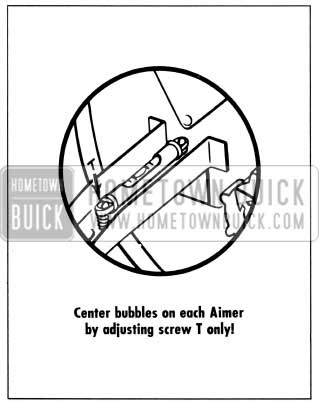
Regardless of the method used in obtaining .a satisfactory aiming surface for all wheelbases, the aimer is now calibrated for the particular floor surface.
1956 Buick Headlight Adjusting Pointer
SECTION 10-F SIGNAL SYSTEM
10-14 HORN
The 1956 horn has one change in its construction. The wire terminal has been removed from the back shell to the horn. Instead, a wire will lead directly from the inside of the horn to the junction block.
SECTION 10-G INSTRUMENTS AND LIGHTS
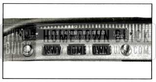
10-15 ARRANGEMENT OF INSTRUMENTS
All series will have new instruments. A speedometer similar to the thermometer-type used in the 1955 50 & 70 series will be used in all 1956 models. The oil pressure gauge, fuel gauge, odometer, charge indicator, and temperature gauge are in a cluster in one housing with the speedometer, but the temperature gauge, oil pressure gauge and odometer give the appearance of being individually mounted on the instrument panel. The charge indicator gauge is mounted on the left side of the speedometer and the fuel gauge is mounted on the right side. The odometer, temperature gauge, and oil pressure gauge are mounted directly below the speedometer with the odometer in the center, the temperature gauge on the left, and the oil pressure gauge on the right. See figure 10-17.
1956 Buick Instrument Arrangement
A new rectangular clock to match the design of the other instruments is mounted on the passengers side of the instrument panel above the glove box door along the same level as the speedometer.
All gauges are of completely new design. The temperature and oil gauges are of the disc type and both work on the same principle. In each gauge there are two discs. One disc is stationery and is painted red and green; the other disc has two windows with a white pointer dividing them. The windows allow the red or green or both to show through. The area painted red and green varies according to the instrument. The charge indicator and fuel gauge have a white pointer swinging in front of a red and green dial.
10-16 OPERATION OF INSTRUMENTS
As the ignition is turned on these instruments will notify the driver as to the operation of the parts represented by the instruments. When the charge indicator shows no charge the white pointer will lie between the red and green areas.
As the generator starts charging, the pointer will move into the green area or into the red area if discharging.
The fuel gauge pointer is in front of the green background until the gasoline supply is slightly below the 1/4 full level, then the pointer will be in front of the red area until it reaches “E.”
The temperature gauge shows green through both windows until an unsafe temperature is approached. It will then show red through the right window and green through the left window. When the temperature becomes dangerously high both windows will show red.
The oil pressure gauge works the same as the temperature gauge. With oil pressure both windows will be green; when unsafe, green will show through right window and red through left window; when dangerously low pressure occurs, both windows will show red.
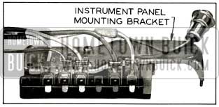
10-17 LIGHTING SWITCH
The light switch is mounted slightly above and to the left of the steering column. The switch has been redesigned with push-in-type wire terminals. Each terminal on the switch is color-coded to match the color of the wire. There are two white terminals, two red terminals, one yellow terminal, and one grey terminal. Each terminal is stamped with an abbreviation of its use. The first white terminal adjacent to the two red terminals is the instrument light plug; the two red terminals are for the battery wire and antenna lead, these may be connected interchangeably; the yellow terminal is for the headlight wire; the grey terminal is for the tail light wire, the second white terminal is for the parking light wire.
In order to avoid crossing wires when making the connections, each wire leading from the wiring harness is just long enough to reach its respective plug.
1956 Buick Lighting Switch
A rheostat, which controls the intensity of the instrument lights, is operated by turning the light switch knob to the left or right. The rheostat in 1956 series does not control the map light.
10-18 MAP LIGHT AND SWITCH
The map light is located in the center of the instrument panel beneath the upper roll of the panel. The map light comes on when either of the front doors of the 40 and 60 series are opened and when any door is opened on the 50 and 70 series. The map light may also be operated when all doors are closed by means of a map light switch which has been removed from the light switch and relocated on the left side of the map light.
10-19 GLOVE BOX LIGHT AND SWITCH
To increase the life of the glove box bulb the lamp socket assy. has been separated from the switch and is now mounted to the glove box in the upper left hand corner. The switch is located in the upper left hand corner of the door opening.
10-20 CIGAR LIGHTER
The cigar lighter is located above and slightly to the right of the steering column and in the same plane as the lighting switch. The lighter is equipped with an ash guard, to prevent ashes and loose tobacco from falling on the user’s clothing and to permit the lighter to be passed around without danger of burning the fingers. This ash guard is a metal ring which extends out over the heating element when the lighter is removed, thereby forming a cup to catch ashes and loose tobacco.
10-21 IGNITION SWITCH
The ignition switch is the same as used in 1953. It is located to the right of the steering column on the lower edge of the instrument panel. A no-steal device will be used to prevent anyone from starting the car by jumping the ignition wires. This device is merely a sheet metal plate covering the ignition switch terminals. It is fastened into place with two clutch-head screws.
10-22 PARKING BRAKE WARNING SIGNAL
All series have the parking brake warning light mounted to the left of the steering column on the lower roll of the instrument panel.
10-23 REMOVAL AND REPLACEMENT OF SPEEDOMETER AND GAUGES
The speedometer, oil pressure gauge, temperature gauge, ammeter, and fuel gauge are individually mounted in a single housing which is attached to the instrument panel by four studs. Each of the instruments with the exception of the ammeter and speedometer may be removed from the housing while it is still attached to the instrument panel. However, a defroster duct interferes with the removal of the ammeter and it is necessary to remove all gauges and the housing before removing the speedometer.
Removal of Instrument Housing
- Disconnect battery.
- Disconnect heater-defroster control panel from the instrument panel.
- Disconnect control wire from the bottom of the defroster air distribution duct. This is done to avoid bending the wire when lowering the radio.
- Remove the long defroster air hose which extends across the length of the cowl and is clipped to the defroster air distribution duct.
- Remove radio and left radio bracket.
- Disconnect fuse block from mounting.
- Disconnect trip odometer reset knob from instrument panel, speedometer cable from speedometer, and pipe from oil pressure gauge.
- Remove temperature gauge and light sockets from housing letting them hang to one side.
- Remove nuts from the four studs on which the housing is mounted. The housing can then be removed by sliding it to the right and down through the opening left by removal of radio.
In case the temperature gauge has to be removed it is advisable to detach the defroster air distribution duct from cowl so that the capillary tube may be easily pulled through the cowl.
SECTION 10-H WIRING CIRCUIT DIAGRAMS
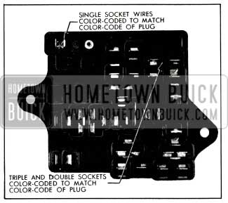
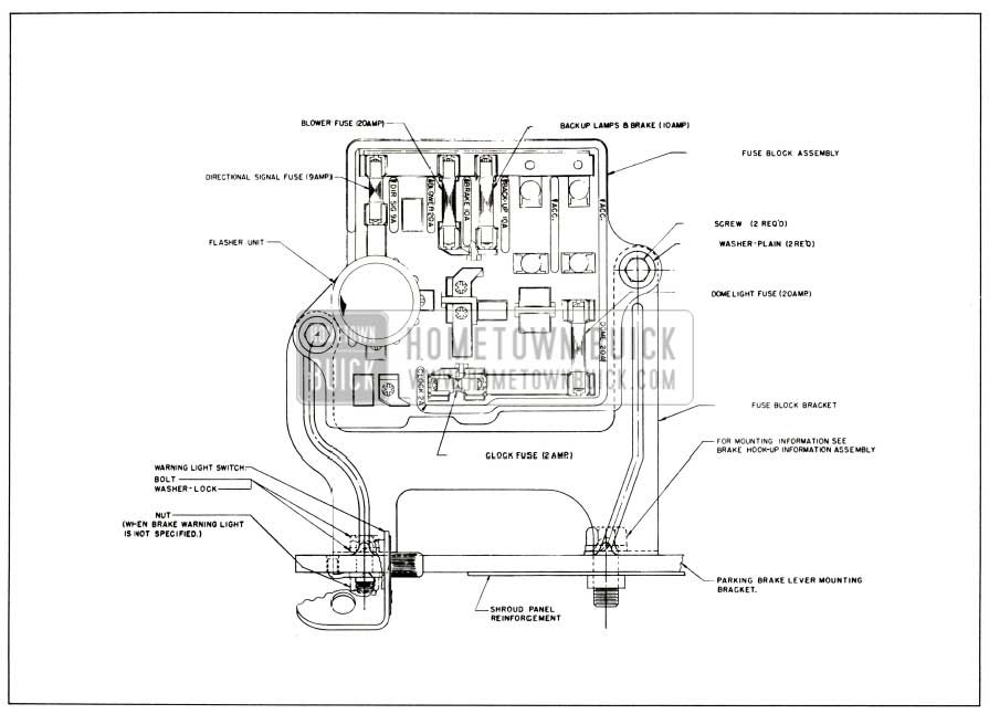
10-24 FUSE BLOCK
A newly designed fuse block is being used on all series. The fuse block is located on the left side of the instrument panel beneath the cowl in approximately the same place as in
1955 series. With the new design all wires will plug into the top of the block. This leaves the fuse area clear of wire terminals. The fuse block plugs are color-coded to match the color code of the wires and sockets. Single sockets, double sockets, and triple sockets are attached to the wires.
For single sockets the color of the wire will designate their respective plugs on the fuse block; for double and triple sockets the color of the socket designates their respective plugs on the fuse block. See figure 10-19.
1956 Buick Fuse Block Top View
As in 1955 the directional signal flasher will plug into the fuse side of the fuse block.
10-25 CIRCUIT DIAGRAMS
This section contains wiring circuit diagrams for chassis and body. The wiring may be easily followed by paying attention to the color code on each wire and the color code indicated on the diagrams.
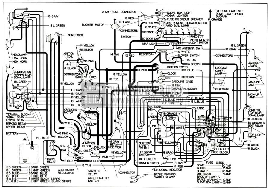
1956 Buick Chassis Wiring Diagram-Dynaflow Transmission
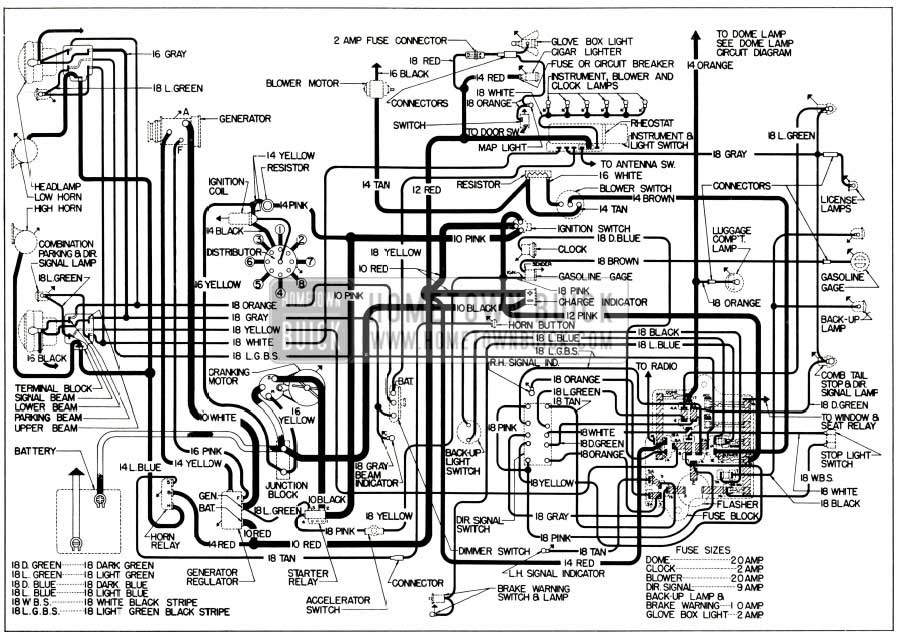
1956 Buick Chassis Wiring Diagram-Synchromesh Transmission
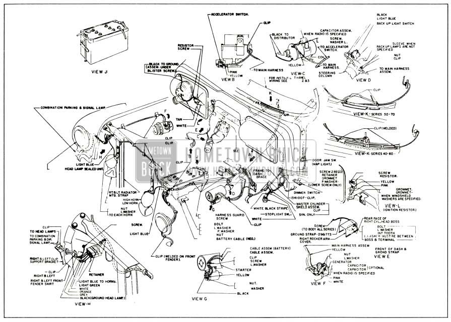
1956 Buick Front End Wiring

1956 Buick Instrument Panel Wiring
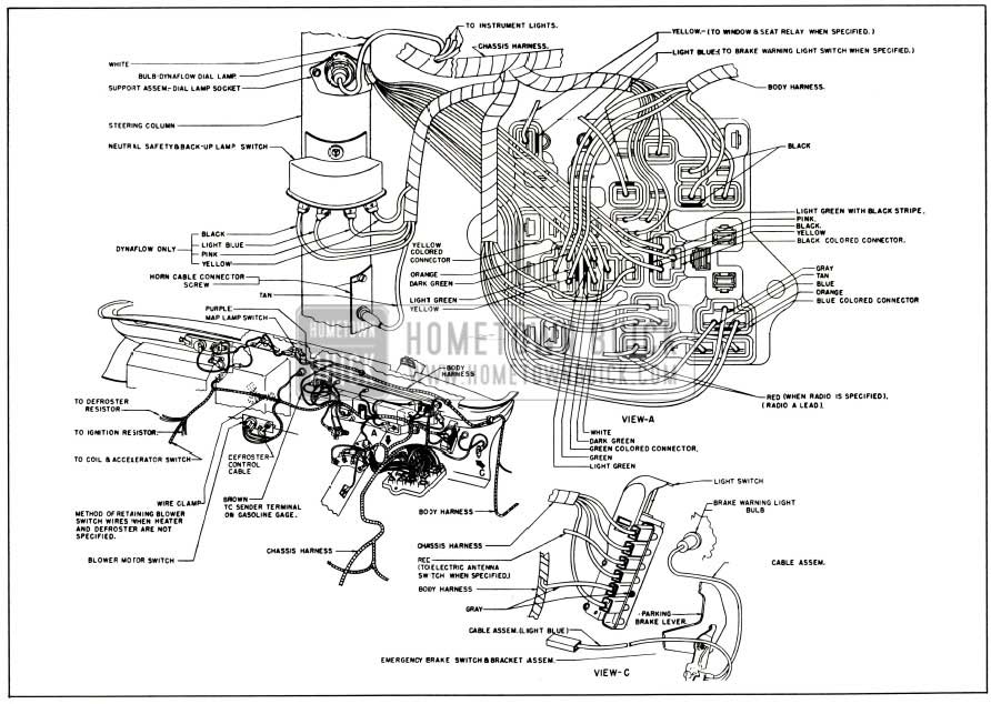
1956 Buick Instrument Panel Wiring Color Code
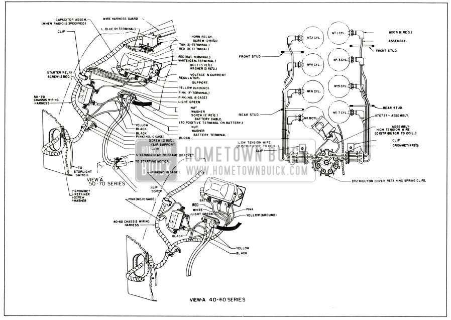
1956 Buick Engine Wiring
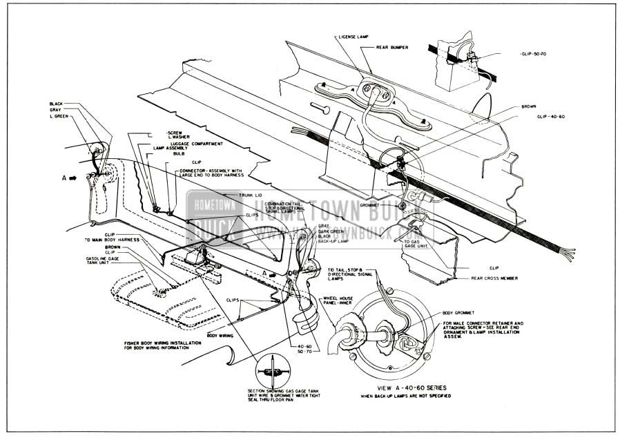
1956 Buick Rear End Wiring
1956 Buick Fuse Block
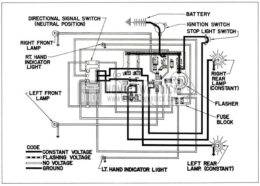
1956 Buick Directional Signal Lamp Circuit-No Turn Indicated (Stop Light On)
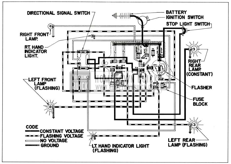
1956 Buick Directional Signal Lamp Circuit-Left Tum Indicated (Right Stop Light On)
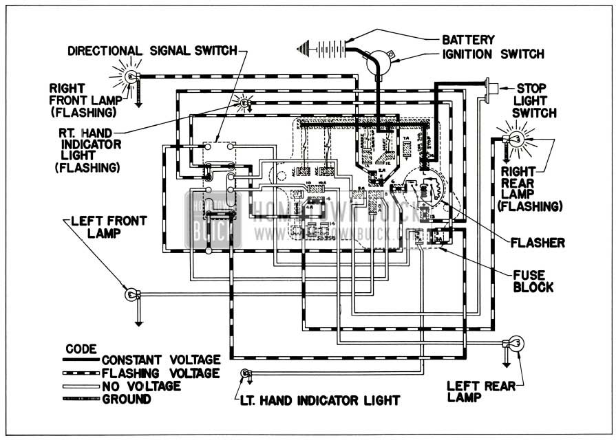
1956 Buick Directional Signal Lamp Circuit-Right Turn Indicated (Stop Lights Off)
Leave A Comment
You must be logged in to post a comment.