SECTION 9-A 1956 BUICK STANDARD BRAKES
9-1 GENERAL INFORMATION
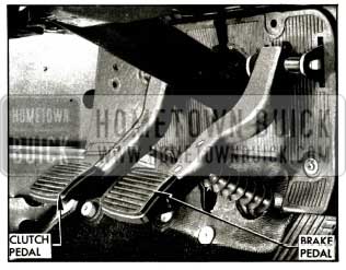
Suspended Pedals
Both hydraulic and power brake pedals are suspended from a bracket located on the dash panel under the instrument panel. This type pedal suspension permits relocation of the master and power brake cylinders. Relocation of these units results in better sealing of the body, improved pedal action, and added protection of the linkage from weather. The standard brake pedal is not adjustable. See Figure 9-1.
1956 Buick Suspended Pedals-Standard Brakes and Synchromesh Transmission
Check Valve and Junction Block
In 1956 the hydraulic check valve has been moved from the master cylinder to the junction block.
The junction block has been relocated and is now bolted to the inside of the front center cross member extension just behind the pitman shaft. There are only two outgoing lines in the new junction block in place of three as previously used.
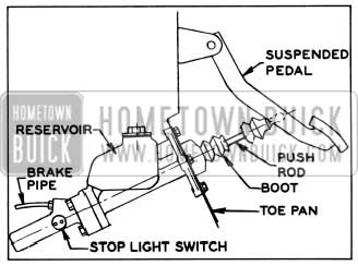
Stop Light Switch
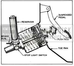
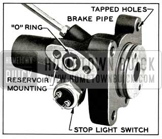
In 1956 the stop light switch is screwed into the hydraulic cylinder housing on both the standard master cylinder and power brake cylinder. See Figure 9-2.
1956 Buick Suspended Pedal and Master Cylinder
Brake Lining and Drums
The width of the 40 series rear brake lining and drum has been increased from 1.75 inches to 2.25 inches, to provide for more effective braking and longer life.
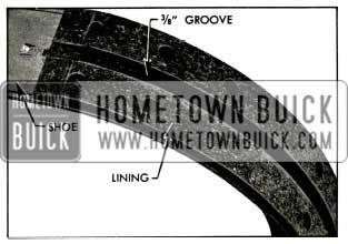
The lining of all shoes in all series have a groove 3/8 inch wide. The groove relieves the high pressure zone over the shoe web thereby increasing the responsiveness of the brakes. See Figure 9-3.
1956 Buick Brake Lining Showing Groove
9-2 1956 BUICK BRAKE MASTER CYLINDER
Description
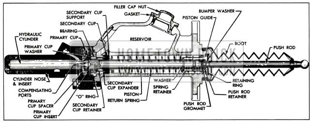
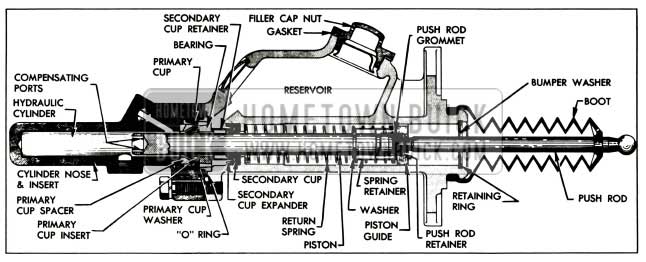
In 1956, the master brake cylinder is entirely new. The new master cylinder is located under the hood on the left hand side and is bolted to the toe pan directly forward of the pedal pad. Due to the 1.5:1 ratio of the suspended pedal, a displacement type cylinder is used. The new displacement type cylinder has a softer pedal and eliminates the need for any linkage adjustment between the pedal and the pushrod. The hydraulic piston in the new cylinder has a maximum travel of 4″.
The master cylinder is directly connected to the brake pedal by the push rod and requires no pedal linkage adjustment.
Operation
As with the previous master cylinder, when the brakes are fully released, the hydraulic piston is withheld from the hydraulic cylinder by means of a return spring that is built into the master cylinder. In the released position, brake fluid is allowed to flow from the reservoir to the hydraulic cylinder through compensating ports. The pressure chamber is filled with fluid at atmospheric pressure due to the open compensating ports and reservoir vent. Lines and wheel cylinders are filled with fluid under a “static” pressure of 8-16 pounds. This pressure holds the lips of the wheel cylinder cups in firm contact with the cylinder walls to prevent loss of fluid or entrance of air. See Figure 9-4.
1956 Buick Master Cylinder-Released Position
When the brake pedal is depressed to apply the brakes, the push rod forces the hydraulic piston into the hydraulic cylinder. As this movement starts, the compensating ports on the piston pass through the primary cup, closing off the reservoir from the hydraulic cylinder, and preventing fluid from escaping to the reservoir. Continued movement of the piston builds pressure in the pressure chamber and fluid is then forced through the lines to all wheel cylinders. Fluid forced into wheel cylinders between the pistons and cups causes the pistons and connecting links to move outward and forces the brake shoes into contact with the drums. See Figure 9-5.
1956 Buick Master Cylinder-Applied Position
When the brake pedal is released, the return spring in the master cylinder pushes the push rod pedal back until piston is in fully released position.
At the start of a fast release the piston moves faster than fluid can follow it in returning from lines and wheel cylinders; therefore, a partial vacuum is momentarily created in the hydraulic cylinder. Fluid supplied by the reservoir then flows around the primary cup lips to keep hydraulic cylinder filled.
As pressure drops in the hydraulic cylinder, the shoe springs retract all brake shoes and connecting links push the wheel cylinder pistons inward, forcing fluid back to hydraulic cylinder. The pressure of fluid and force of return spring causes piston and pedal to be forced into released position. With piston in the released position, the compensating ports are open to the reservoir; therefore, the excess fluid that is caused by expansion due to increase in temperature and the fluid that entered around the primary cup during fast release is able to flow back to reservoir.
When the pressure in wheel cylinders and pipes becomes less than the spring tension of the check valve inside the junction block the valve closes, maintaining static pressure in the lines and wheel cylinders.
Removal and Installation of Master Cylinder
- Disconnect brake pipe from master cylinder and tape end of pipe to prevent entrance of dirt.
- Disconnect stop light wires from stop light switch.
- Disconnect push rod from brake pedal and remove brake pedal.
- Remove screws holding steering column jacket rubber seal retainer to fire wall and push it up on the steering column jacket.
- Pull the floor mat away from toe pan and remove toe pan. The master cylinder is connected to the toe pan.
- To remove toe pan from cylinder, remove the three attaching bolts.
- To install, reverse procedure.
Brake Master Cylinder Overhaul
- Remove master cylinder from car.
- Remove toe pan from master cylinder. A heat shield must also be removed if car is equipped with a synchromesh transmission.
- Clean outside of master cylinder thoroughly, remove filler cap and drain hydraulic fluid from reservoir.
- Place master cylinder in vise in vertical position with push rod up. Remove boot from push rod and using No. 1 Truarc Ring Pliers, J-4245, remove retaining ring and guide bumper washer. Remove push rod and piston from body.
- Remove return spring, retainer and piston washer. To disassemble push rod from piston, insert the piston into a 9/16″ I.D. washer and support the washer on the jaws of a vise.
CAUTION: Protect the piston from jaws of vise with a cloth. Do not clamp piston in vise. Hold piston and strike the push rod with a soft headed mallet to drive piston out of piston guide. See Figure 9-6.
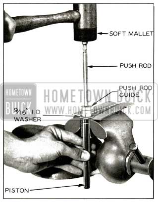
1956 Buick Disassembly of Push Rod and Piston
Then remove grommet and push rod retainer from end of push rod.
Inspect the bore from push rod end for pits, scoring, rust and dirt. Check counterbore on opposite end. This surface must be smooth and free from pit marks, scores, rust and dirt. Check the machined face and threads in three mounting holes at each end of cylinder. Be sure the reservoir is clean and the filler cap hole threads are undamaged. Make sure the hole from the reservoir to the bore is clean and open. Remove stop light switch from nose piece and check threads of switch and casting hole.
The body castings and all parts may be washed in Declene or a good grade of clean alcohol. Never use gasoline, kerosene, or any mineral base oil. Inspect all parts after cleaning and replace any that are damaged or worn. Replace filler cap and new gasket loosely in reservoir to keep out dirt during assembly. Replace stop light switch.
The bores of the master cylinder body and nose piece may be cleaned and reconditioned with fine crocus cloth if not too deeply pitted or scratched. The chrome finish of the piston should never be sanded. The piston should be replaced if damaged along with all other internal working parts.
Install piston washer, spring retainer, and return spring on piston.
SECTION 9-B 1956 BUICK POWER BRAKES
Power brakes are available only on cars equipped with Dynaflow because the connecting linkage of a synchromesh transmission interferes with the cylinder.
9-3 POWER BRAKE CYLINDER AND PEDAL
Description
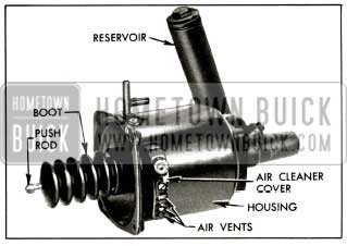
The power brake cylinder has been relocated under the hood and is bolted to the toe pan. The power brake cylinder is directly connected to the brake pedal by the push rod. The power brake pedal also utilizes a ratio of 1.5:1 with the new suspended pedal. See Figure 9-7.
1956 Buick Suspended Pedal and Power Brake Cylinder
Changes in the Power Brake Cylinder Housing
The power brake cylinder for 1956 is basically the same as the 1955 unit except for these changes.
- A snubber, which is a small rubber washer bonded to a metallic ring, has been added to the air control valve and is located between the air valve spacers and valve reaction plate. The snubber will eliminate metallic click created when the air valve engages against the valve reaction plate. See Figure 9-8.
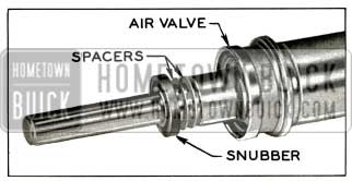
1956 Buick Air Valve and Snubber
1956 Buick Power Cylinder
External Changes in Hydraulic Cylinder
The external changes resulting from redesigning the hydraulic cylinder are as follows:
- The hydraulic cylinder is shorter in length.
- The bolts that hold the power cylinder to the hydraulic cylinder are screwed into the hydraulic cylinder. See Figure 9-10.
1956 Buick Hydraulic Cylinder-Reservoir Removed
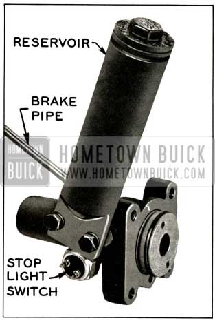
1956 Buick Hydraulic Cylinder, Stop Light Switch, and Reservoir
Adjustment of the Pedal
On power brakes only, the suspended pedal is adjustable. This adjustment allows positioning of the pedal to prevent the push rod from binding. See Figure 9-12.

1956 Buick Power Brake Suspended Pedal
To position the pedal:
- Loosen the nut on the right side of the bracket.
- Turn the eccentric pedal pivot bolt on the left side to adjust pedal vertically until the pedal and push rod operate free of any bind. By depressing rubber boot around air valve the approximate center location at the push rod through the air valve can be established.
- Hold the eccentric pedal pivot bolt and tighten the nut until the mechanism is secure.
Removal and Installation of Power Brake Cylinder
To remove and install the power brake cylinder, follow the same procedure for removal and installation of master cylinder as outlined in paragraph 9-2 (c) except for the following: After the first step, disconnect vacuum lines from power brake cylinder. Then place drip pan under power cylinder reservoir and remove reservoir from unit.
Overhaul of Power Cylinder
The same procedure is used to overhaul the 1956 power brake cylinder as was used in 1955 except for removal and installation of snubber valve reaction plate and valve diaphragm spring, it is necessary to remove the snubber before removing air valve spacers. During assembly reverse these procedures. It is important that the snubber is installed after the gauging and reinstallation of the proper number of spacers. However, the snubber should not be used on 1955 power cylinders.
Vacuum Check Valve and Vacuum Tank
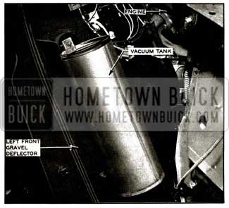
The vacuum check valve is now located on the vacuum line between the cylinder and the intake manifold. The vacuum tank is now bolted on the back of the left gravel deflector at the left front fender in a vertical position. See Figure 9-13.
1956 Buick Vacuum Tank
The length of the vacuum lines and the number of connections have been reduced due to the relocation of the power cylinder and the vacuum tank.
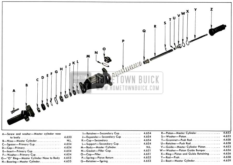
1956 Buick Master Cylinder
Leave A Comment
You must be logged in to post a comment.