DYNAFLOW MANUAL CONTROL
Shift Control Linkage
The shift control lever mounted in the housing at upper end of steering column jacket operates a tubular control shaft located inside the column jacket. When the lever is pulled upward toward the steering wheel the control shaft is moved downward against a return spring until the lower lever is disengaged from a stop plate on steering column jacket. The control shaft can then be rotated by movement of the control lever. The control shaft lower lever operates the transmission shift lever through connecting rods and an idler lever mounted on car frame.
The shift lever operates a cross shaft inside the rear bearing retainer, from which linkages connect to the shift control valve and the parking lock pawl. A spring loaded detent lever and roller engages notches in a detent plate on the cross shaft to hold the control valve in any set position.
Shift Control Linkage Adjustments
When a Dynaflow transmission does not operate properly it is advisable to first check the shift control linkage adjustment, after transmission is warmed up to normal operating temperature and oil is at proper level.
- With shift control lever released, the stop screw in control shaft lower lever must be flush (plus or minus .010″) with upper surface of stop plate. Adjust as required.
- With shift control lever in Drive position, .010″ to .020″ clearance must exist between the stop screw and the upper edge of large opening in stop plate. Since this clearance cannot be readily checked because of location, it may be assured by carefully performing the following adjustment.
- Disconnect lower shift rod clevis from idler lever and make sure that transmission shift lever is held firmly by detent in Drive position.
- With shift control lever on steering column in Drive position, push upward on idler lever to hold the stop screw in contact with stop plate, then adjust clevis in shift rod so that clevis pin will freely enter clevis and lever.
- Shorten length of rod and clevis by turning clevis 1/2 turn up on rod, then install clevis pin with anti-rattle washers and tighten the clevis lock nut. The 1/2 turn of clevis provides the specified clearance at stop pin.
- Park car on ramp or other grade with control lever in Parking (P) position to determine whether parking lock holds securely. Then let car roll with control lever in Neutral (N) position and listen for a clicking or ratchet noise which would indicate that parking lock pawl is contacting the parking lock ratchet wheel.
- If parking lock fails to hold or ratchet noise exists, jack car up so that a wheel may be turned to rotate propeller shaft.
- Loosen the linkage adjusting lever lock bolt on side of rear bearing retainer. With transmission in Neutral, tap rear end of lever upward until a slight ratchet noise is heard when propeller shaft is turned, then tap lever down just enough to eliminate the noise. Tighten lock bolt securely.
- Remove car jacks.
- With transmission warmed up and engine idling at approximately 600 RPM, slowly move control lever from Neutral (N) to Drive (D) position. The clutch should engage, as indicated by an immediate decrease in engine speed when the center of dial pointer is midway between “N” and “D” on speed ratio dial.
- Slowly .move control lever from Drive (D) position to Neutral (N) position. Clutch should disengage, as indicated by an immediate increase in engine speed, when center of speed ratio pointer is midway between “D” and “N” on speed ratio dial.
- If points of clutch engagement and disengagement are not as specified, and all preceeding linkage adjustments have been correctly made, it will be necessary to remove transmission oil pan and adjust the position of the shift control valve as shown in figures 5-35 and 5-36 in the 1955 Product School Manual, observing instructions in the related text.
TORQUE BALL BOOT CHANGE
A new Torque Ball Boot is now being used in production. This new Torque Ball Boot, while different in appearance, may be used optionally with the old type since they are completely interchangeable.
The Parts Department advises that stock of the old type boot is now exhausted and only the new type boot, Group 5.565 Part No. 1170199 will be supplied for all service replacements.
DYNAFLOW INPUT SHAFT BEARING
Recently Engineering released an input shaft, needle bearing, and reaction shaft and flange assembly as described in B.P.S. 2.391. This bearing replaced the Babbitt type bushing on approximately 3200 jobs. Because of the improvement made with the Babbitt bushing which has been substantiated by service reports, it has been decided that the Babbitt bushing will continue to be used in 1955 with the corresponding reaction shaft and flange assembly and input shaft.
The improvement in gear noise with the Babbitt bushing as compared to early production transmissions has been attributed to improved surface finish on the shaft journal diameter which greatly reduced bushing wear. Since this latest improvement, Engineering feels that there is no particular advantage in using a needle bearing.
Whenever a case is found where there appears to be abnormally fast wear on the Babbitt type input shaft bearing, we suggest that the bearing be replaced as described in paragraph 5-18, sub. par.a, 1955 Shop Manual. However, in order to increase the life of the new bearing it is absolutely essential to polish the main shaft journal area with oil soaked crocus cloth or replace with new shaft having a good finish. It is not necessary to polish all scratches out, but just take off all rough spots, which would tend to scrape the bearing.
The Parts Department will supply parts for both the needle bearing and the Babbitt bearing jobs.
FLUSHING DYNAFLOW OIL COOLER
It is recommended that whenever it is necessary to completely disassemble and clean a Dynaflow transmission during an overhaul, that the oil cooler also be flushed out thoroughly in order to remove any abrasive material that might have been carried into the cooler.
The oil cooler may be reverse flushed using kerosene in the oil passages. Pour the kerosene into the outlet side of the cooler, then trapping the oil tin the cooler, shake vigorously. After shaking, allow the kerosene to drain from the inlet. Repeat this until the kerosene leaves the cooler, clean and free from abrasive particles.
DYNAFLOW WHINE
Excessive Dynaflow whine is usually the result of excessive clearance between the input shaft and the bearing in the reaction shaft. (Bearing shown in Figure 5-60, 1955 Shop Manual.)
If a Dynaflow transmission is disassembled to correct whine, perform the following:
Note: When excessive clearance exists at this point, the input shaft and planetary carrier have excessive radial run-out which results in improperly meshed convertor planetary gears.
- Remove converter cover, twin turbine assembly, and sun gear, then mount dial indicator on the end of the input shaft with indicator button contacting reaction shaft. Position indicator button 90° to the left of top center (facing end of shaft) then move input shaft away from and toward indicator while noting the gauge reading. Repeat this check at 45° to the left of top center and again at top center, then 45° to the right of top center. If dial reading exceeds .005“, excessive clearance exists between input shaft and bearing in reaction shaft.
- Before replacing bearing, remove reaction flange assembly and input shaft and observe the following:
- Inspect bearing surface on input shaft. If surface appears abnormally rough or scored, replace input shaft; if not, polish journal area with crocus cloth.
- Inspect the two oil seal rings toward rear of input shaft and the mating surface in reaction shaft for scoring or other damage. If reaction shaft or input shaft shows evidence of scoring or other damage, replace worn or damaged parts.
- If inspection reveals that condition of reaction shaft and input shaft are satisfactory, replace only the input shaft bearing as described in paragraph 5-18, sub-par. a, 1955 Shop Manual.
- If input shaft, reaction flange, or the bearing requires replacement, it will also be necessary to replace the converter sun gear and planet pinions.
NOTE: When installing reaction flange service bushing, be sure the assembly is supported on the rear end of reaction shaft to prevent distortion of the aluminum reaction flange.
It is not generally necessary to replace converter ring gear unless unusual wear can be observed.
One or more of the above described parts may be required to correct a ”whine” complaint; however, it is important to make necessary inspections and exercise good judgment regarding parts replacement.
STATOR SCREW TORQUE SPECIFICATION
The Engineering Department recommends that a torque specification of 10-12 ft. lb. be applied to the stator carrier screws using tool J -5826. Stator assembly screw remover and replacer (this tool is included in the 1955 essential tool kit, however it will be the bit type rather than the screwdriver type shown on page 68 of the 1955 Product School Manual).
This torque specification is necessary to insure a proper fit of the stator blade crank in the carrier and prevent leakage at the split line.
SHIFT CONTROL VALVE ADJUSTMENT
1955 DYNAFLOW
Following is a reprint of Special (Red Band) Service Letter Dealer No. 153 dated March 8, 1955.
We have received several reports of improperly adjusted shift control valves in 1955 Dynaflow Transmissions. Since the publication of the initial product information and Shop Manual, there have been some slight changes in the adjustment procedure which will provide a more positive method of properly positioning the shift control valve in all operating ranges.
The following adjustment procedure .now applies to the Dynaflow Shift Control Valve and Linkage:
Shift Control Linkage Adjustments:
When a Dynaflow Transmission does not operate properly it is advisable to first check the shift control linkage adjustment, after transmission is warmed up to normal operating temperature and oil is at proper level.
- With shift control lever released, stop screw in control shaft lower lever must be flush (plus or minus .010″) with upper surfaces of stop plate. Adjust as required.
- With shift control lever in Drive position, .035″ to .050″ clearance must exist between the stop screw and the upper edge of large opening (window) in stop plate. (See Figure 27. Since this clearance cannot be readily checked, because of location, it may be assured by carefully performing the following adjustment.
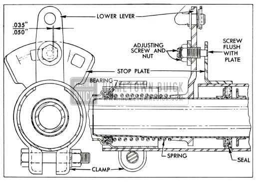
1955 Buick Transmission Shift Lever
- Disconnect lower shift rod clevis from idler lever and make sure that transmission shift lever is firmly held by detent in “Drive” position.
- With shift control lever on steering column in Drive position, push upward on the lever to hold stop screw in contact with stop plate, then adjust clevis in shift rod so that clevis pin will freely enter clevis and lever.
- Shorten length of rod by turning clevis 2 to 3 turns up on rod, then install clevis pin with anti-rattle washers and tighten clevis lock nut. The number of turns at the clevis provides a specified clearance at the stop pin.
- Park car on ramp or other slight grade with control lever in Parking (P) position to determine whether parking lock holds securely. Then let car roll with control lever in Neutral (N) position and listen for a clicking or ratchet noise which indicates that the parking lock pawl is contacting the parking lock ratchet wheel.
- If parking lock fails to hold or ratchet noise exists, jack car up so that a wheel may be turned to rotate propeller shaft.
- Loosen the linkage adjusting lever lock bolt on side of rear bearing retainer. With transmission in Neutral, tap rear end of lever upward until a slight ratchet noise is heard when propeller shaft is turned, then tap lever down just enough to eliminate noise. Tighten lock bolt securely making certain that lever does not change position.
- Set parking brake to prevent rear wheels from turning then start engine, with car still safely jacked up.
- With transmission warmed upward engine idling at approximately 600 RPM, slowly move control lever from Neutral (N) to Drive (D) position. The clutch should engage, as indicated by an immediate decrease in engine speed when the center of dial pointer is midway between “N” and “D” on speed ratio dial.
- Slowly move control lever from Drive (D) position to Neutral (N) position. Clutch should disengage, as indicated by an immediate increase in engine speed, when center of speed ratio pointer is midway between “D” and “N” on speed ratio dial.
- If points of clutch engagement and disengagement are not as specified, and all preceeding linkage adjustments have been correctly made, it will be necessary to remove transmission oil pan, oil suction screen, and adjust the position of the shift control valve as described below.
Adjustment of Shift Control Valve
Slight changes have been made in the shift control valve; however, these changes do not affect adjustment procedure.
In order to prevent overtravel of valve when shifting into reverse, an extension has been added to the end of the shift control valve which will act as a valve stop.
As shown in Figure 28, the first type shift control valve has no extension, the second type valve has a plain extension, and the third type valve has a grooved extension. All three of the above valves are suitable for use in the transmission.
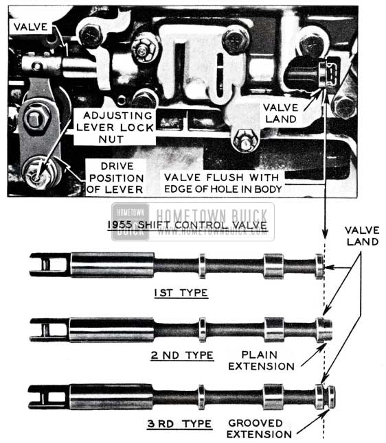
1955 Buick Shift Control Valve
To properly position shift control valve in the valve body, proceed as follows:
- With the transmission oil pan and oil suction screen removed, shift the transmission into drive range, then note the position of the land as shown in Figure 28 on the shift control valve in relation to the edge of the hole in the valve body.
- The edge of land on the shift control valve must be flush with the edge of the hole in the valve body as shown in Figure28.
NOTE: Disregard valve extension (if present) on end of shift control valve. Do not mistake the end of the valve extension with the valve land during the valve adjustment.
- If the edge of the valve land does not line up with the edge of the hole in the valve body, loosen the adjusting lever lock nut and properly position shift control valve, then securely tighten lock nut.
IMPORTANT: Previous adjustment procedures included a clearance check between the outer end of the shift control valve and the stop pin in the servo body. However, because the later adjustment procedure provides a more positive valve location and port opening for all range positions, this clearance check is no longer necessary.
The above shift control valve adjustment, with regard to the valve body and land position applies whether the adjustment is made in the car or during transmission assembly. The rear bearing retainer, (parking pawl) adjustment may be made with rear bearing retainer removed, as described in the 1955
Shop Manual, then the position of the shift control valve in the valve body may be made as described above.
After any adjustments or service have been performed an operational check should always be made.
DYNAFLOW FAILURE REPORTS
Whenever a Dynaflow transmission is repaired because of clutch failure, our Engineering Department would like to have a product report (submitted in the regular manner) including information; as to whether or not the clutch plates were installed as follows:
- Were the clutch plates dished in the same direction?
- Were they spaced properly?
- Was the external (Plain Steel) splined plate against the clutch piston?
BUZZING NOISE TRANSMISSION CONTROL SHAFT
We have received a few reports of a buzzing noise coming from the transmission control shaft return spring.
This noise is caused by the compressed spring vibrating in resonance with some other force in the car and can easily be detected by moving the transmission control lever toward the steering wheel. This increases the spring compression and changes the frequency at which the spring will make the buzzing sound. If this operation (moving the shift lever toward the wheel) stops the bussing noise while the lever is raised, it can be reasonable certain that the transmission control shaft return spring is causing the noise.
Of several methods used to eliminate this noise, the following method was the best. Using a small, stiff bristle brush, the exposed portion of the transmission control shaft return spring should be coated with a light covering of Underbody Sealer, direct from the can without thinning. See Figure 29.
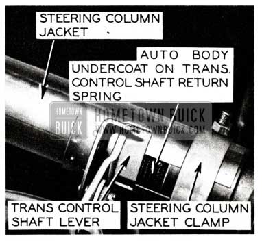
1955 Buick Transmission Control Shaft
This coating decreases the vibration frequency of the spring and eliminates the noise.
1955 DYNAFLOW TEST
Performed at New Car Make Ready and 2000 Mile Inspection.
- Connect tachometer to indicate engine speed.
- With engine running, brakes applied, observe tachometer while slowly depressing accelerator pedal to wide open throttle position.
- The stator blades should move to the high angle position, as indicated by a sudden increase of engine RPM (approximately 1000 RPM) during the last half inch of accelerator pedal travel.
CAUTION: Do not run engine any longer than necessary to perform test under the above condition; otherwise Dynaflow oil temperature will rapidly increase and may also be detrimental to a new engine.
DYNAFLOW SHIFT LINKAGE
It has been brought to our attention that in some cases, dealer mechanics are filing the shift detent plate (which is welded to the valve operating cross shaft located in the rear bearing retainer) because of difficulty in adjusting the linkage. It must be understood that the valve operating cross shaft and plate assembly are carefully machined and case hardened so that proper shift location will exist when the roller is engaged in any of the detents. Therefore, filing or grinding of this plate can result in rapid wear and also change position of the shift control valve so that improper Dynaflow operation would result.
If correct adjustment of the shift linkage cannot t>e obtained and it is definitely established that the detent plate is at fault, the valve operating cross shaft assembly Gr. #4.270 Part #1166146 should be replaced rather than file or grind the detent plate.
Leave A Comment
You must be logged in to post a comment.