1955 BUICK REAR AXLE CHANGES
Because of the many changes that have been made in the rear axle assembly since the beginning of 1955 production, the following information was prepared to describe the initial rear axle changes and subsequent changes made up until present production. Following the recap of these changes will be detailed service procedures and information pertaining to interchangeability of new parts with past model rear axle assemblies.
Since the beginning of 1955 production changes in the rear axle assembly consisted of the following:
- One new Departure double row radial thrust ball bearing (front) and one new Hyatt roller bearing (rear) used with a longer lock sleeve and wider spacer. See Figure 30.
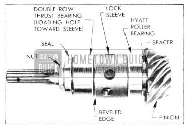
1955 Buick Rear Axle – Exploded View
The load angle of the double row ball bearing has been changed whereby the thrust on each row of balls is placed closer to the bearing center. This design permits slight variation in alignment under load to be absorbed without causing excessive cramping load on the bearing. The end shield has also been eliminated from this bearing as it is no longer required; however, the oil seal has been redesigned to set flush with the bearing end to provide an effective seal.
The rear bearing is a single radial roller bearing which replaces two roller bearings of the previous design. The new type single roller bearing is longer than that of the previous design and provides greater life factor, while allowing for slight alignment variation under load without end-pinch on rollers.
The new roller spacer and lock sleeve places the rear bearing deeper into the carrier bore to provide more bearing support. Dimensional changes in lock sleeve (longer) and roller spacer (wider) compensate for the elimination of one bearing.
- Improved lubrication within the axle is provided by relocation and enlarged feed holes to the pinion bearings and a revised gear channel shape in the rear cover which redirects more oil to the differential side bearings. A rear axle vent used in 1954 is continued for 1955. It is located on top of left arm of housing just inside of rear spring seat and it prevents build-up of pressure within the axle and decreases the possibility of oil leakage.
- At the time the above changes were made the ring gear was riveted to the differential case; however, since then a bolted type ring gear, which is attached to the differential case with twelve (12) special alloy steel bolts, has gone into production. In this design the ring gear attaching bolts are threaded directly into the ring gear web for maximum holding power and provide a bond between case and ring gear of approximately 100,000 pounds of clamping force which causes the case flange and ring gear to function as one unit, mutually supporting against deflections under load taking the driving force directly from gear to case by friction rather than through a shearing force on the rivets.
- Following the bolted ring gear into production were changes in the rear axle carrier, whereby the width of the bolting flange was increased from .620″ to .800″ and the reinforcement ribs (on ring gear side of carrier) were extended to the outer circumference of this bolting flange. See Fig. 31 & 32.
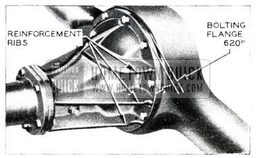
1955 Buick Rear Axle Improvement
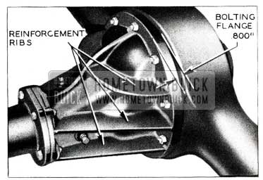
1955 Buick Rear Axle Reinforcement
These design changes were made to add strength to the carrier housing.
- Following the strengthened carrier into production was a tapered pinion (taper on back face of pinion) designed with a shoulder to provide added strength. See Figure 33.
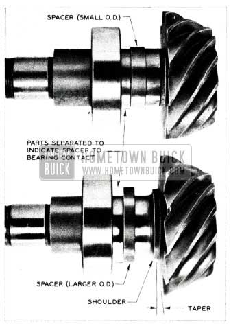
1955 Buick Rear Axle Spacer
These changes require the use of a new spacer having a larger diameter to compensate for the dimensional changes made in the pinion. See Figure 33.
- A new method of attaching rear axle housing to the third member housing (carrier) followed the tapered type pinion into production. The bolts attaching the rear axle housing to the carrier previously passed through holes in the carrier and threaded into tapped holes in the axle housing. These bolts are now being replaced by ten (10) studs which are pressed into the axle housing flange. See Figure 34.
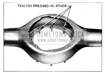
1955 Buick Rear Axle Housing
During assembly, the carrier is mounted on these studs, then ten (10) 3/8 – 24 nuts (without lockwasher) are installed and torqued to 50-60 ft. lb., which is approximately three (3) times the torque specified for the bolts previously used. This design provides more rigidity and reduces the possibility of oil leakage.
SERVICE PROCEDURES
PINION BEARING REPLACEMENT
The new shieldless double row radial thrust ball bearing (Part No. 954919) may be used as a replacement for any past model front pinion bearing with shield (where a pinion seal was used); however, the new oil seal (Part No. 1339437) and new bearing (Part. No. 954919) must always be used together or interference with hex nut may result.
If the new bearing arrangement (with one rear roller bearing) is to be installed in a rear axle in which the old arrangement has previously been run, a new gear set must also be used. The reason for this is if the new bearing arrangement was installed on a pinion previously equipped with two rear roller bearings, the new single roller bearing (rear) would rest on a ridge created by wear pattern of the two radial bearings previously used. As the ridge, not usually noticeable, occurs between the two radial bearings, it can be understood that the load on the single rear bearing would be carried on this narrow ridge and only a small portion of the bearing. The ridge would then act as a fulcrum causing the bearing to tilt with load variation and in time it would result in premature bearing failure.
Installation of the new bearing arrangement on pinion shaft should be made as indicated in Figure 30.
Procedures for setting the first type pinion (not tapered) are unchanged and should be performed in the usual manner except for the following:
A new pinion bearing spacer (J -5905) is used to press the pinion gear into the carrier. The new tool consists of two pieces, a spacer similar to the 1954 tool with a handle, and an additional spacer with a chain attached. When positioning the tool for use, the spacer with handle is positioned next to the bearing while the additional spacer (with chain attached) is positioned next to the pinion. See Figure 35.
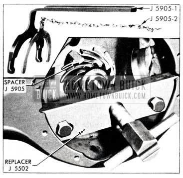
1955 Buick Pinion Bearing Spacer
Following the pressing of the pinion into place, the chain may be used to pull one part of the spacer out, leaving sufficient space to remove the balance of the tool.
NOTE: The spacer tool applies the assembling force by way of the outer races of the bearings so that undue force is not exerted on the balls of the front bearing which results in damage and noisy bearings.
BOLTED ON TYPE RING GEAR AND PINION SET
The new bolted-on type ring gear and pinion set may be used for servicing any past model car equipped with wide carrier pedestals. The bolted type ring gear and pinion set consists of a pinion and ring gear less differential case; therefore, when bolted on ring gear and pinion set is to be used as a replacement for the riveted type gear set with old bearing arrangement, dealers should also order the differential case, twelve special bolts and a complete new bearing arrangement in addition to the ring and pinion gears.
NOTE: It is not recommended to attempt reworking a riveted type differential case for a bolted ring gear installation.
Bolts used to assemble the ring gear to the differential case do not require lockwashers; however, they must be tightened to 50-60 ft.lbs. of torque. An initial torque of 25-30 ft. lbs. should be first applied to opposite bolts all around the ring gear and then tightened in the same sequence to the specified 50-60 ft. lbs.
TAPERED PINION TYPE GEAR SET
The tapered pinion type gear set may be used in past models under the same conditions described in “Pinion Bearing Replacement” except that a larger diameter spacer, designed to clear the reinforcement shoulder is used with this type of pinion.
In order to properly press the tapered pm10n into the differential carrier a new spacer tool J -5973 must be used. This tool is designed with a contour to match that of the pinion and is made in two pieces which are hinged together to facilitate installation and removal. A small amount of rear axle lubricant should be placed on the thrust surfaces of the tool. The tool is then placed into position finger-tight with the hinged section at the top as shown in Figure 36.
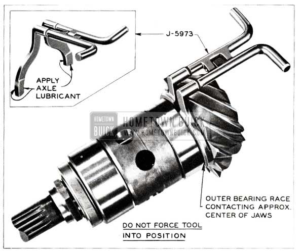
1955 Buick Outer Bearing Race
CAUTION: The tool must not bottom against the pinion shaft or else it will be very difficult to remove. The tool is designed so that when it is properly positioned only about half of the thrust surface is between the pinion and the bearing outer race. With the tool in this position all clearance is removed between the pinion, rear bearing outer race, spacer and front bearing outer race, making it possible to transmit the pressing load on the pinion directly to the outer bearing races.
To remove the tool it may be necessary to tap it gently, then work it out of the carrier by opening the jaws. If excessive force is required to remove the tool, then too much force was used when pressing the tool into place between the pinion and rear bearing outer race.
NOTE: This pinion bearing spacer tool, J -5973, will not work on past models and must only be used on the taper type pinion; likewise, the old tool, J -5905, will not work on tapered pinions.
THIRD MEMBER HOUSING
Whenever the new carrier which has a rear bolting flange thickness of .80Q” is used, it will be necessary to install ten (10) 3/8 – 24 – l lf4 bolts (1/4″ longer than original type) to attach the carrier assembly to the rear axle housing.
After stock of carrier housings having a narrow (.620″) bolting flange is exhausted, the Parts Department will only furnish wide (.800″) flanged carrier housings for all service replacements.
REAR AXLE HOUSING
The Parts Department will only stock the axle housings having pressed-in studs after stock on hand is exhausted. When a housing with pressed in studs is to be used as a replacement for the old type housing (without studs) ten (10) Special Alloy 3/8 – 24 hex nuts must be used. An initial torque of 25-30 ft. lbs. should be first applied to opposite bolts all around the differential carrier flange and then tightened in the same sequence to the specified 50-60 ft. lbs.
PINION BEARING SPACER TOOL
SPACER TOOL J-5973
Order blank for J -5973 pinion bearing spacer may be obtained from your Buick zone Service Manager at his office. See Figure 36.
PRESSING TAPERED PINION IN CARRIER HOUSING
1955 Models
We have received reports that the propeller shaft equipped with a tapered pinion had been installed two, and sometimes three times on a car.
Investigation revealed that the tapered pinion in each case was pressed into the carrier housing without the use of spacer tool J -5973. As previously stated in BPS 2 .388, dated May 6, 1955, page 141, paragraph C – ”In order to properly press the tapered pinion into the differential carrier a new spacer tool J -5973 must be used.”
This tool is designed with a contour to match that of the pinion and is made in two pieces which are hinged together to facilitate installation and removal.
Some dealers service men are trying to install the tapered pinion using tool J -5905 which does not work with the tapered pinion, therefore it is imperative that only the correct tool, J -5973, be used when replacing the tapered pinion.
REAR AXLE GEAR RATIO CHANGE
1955 – 50-60-70 Series
A new 3.36 ratio rear axle ring and pinion gear is being released for 1955 50-60 and 70 Series to replace the 3.4 gear set.
This new ratio gear does not greatly change top speed or gas mileage performance; however, there is considerable improvement in overlapping of the gear tooth contact, which will more efficiently carry the present heavy torque loads. (The 3.4 set has a 12-tooth pinion and 41-tooth ring, while the new 3.36 set has a 14-toothpinionand 47-tooth ring.) Both sets are interchangeable with one another; however, when using pinion setting indicator gauge, J -564 7, to set the pinion depth for the 3.36 ratio rear axle pinion gear, indicator pad “B” should be used.
The table located in the cover of the gauge box should be changed to show 14-47 under the 13-42 for the indicator pad “B” column.
The Parts Department will replace all orders for 3.4 gear sets and ship the new set, Group 5.529, Part No. 1392481 which includes a nut, pin 1 spacer-, shim and lubricant.
BROKEN AXLE FILLER PLUGS
We have received several reports on the cast iron rear axle filler plugs breaking off on 1955 model cars.
These failures have been caused by excessive tightening of- the plug. NOTE: Plugs will break off at 51 ft. lb. or more. The proper torque is 20-30 ft. lb.
It is not required that these plugs be torqued every time the rear axle is checked, but proper range of “feel” of the desired tightness should be practised to prevent over torquing this plug.
REAR AXLE LUBRICANT
Buick is introducing Rear Axle Lubricant in a 120 pound drum. This standard size drum can be attached to a pressure system and will make handling more convenient in your Service Area.
This. Rear Axle Lubricant is compounded to G.M. specification 4655-M and is especially recommended for the Buick Hypoid Rear Axle. The extreme pressures built up between the teeth of the Ring and Pinion Gear in the Buick Axle, demand that the proper lubricant be used for best service.
This extreme pressure lubricant is the most satisfactory which Buick Engineers have found for use in the rear axle.
The 120 pound drum of rear axle lubricant “is available under Group 5.535 Part #1392360 from all Parts Warehouses.
PROPELLER SHAFT STRAIGHTENING
To prevent any distortion or damage to the drive pinion when checking run-out of a propeller shaft, our Engineering Department suggests: If run-out exceeds limits as noted in Figure 37, support the shaft at “A” and “D” or if to advantage “F” and “D” as indicated in Figure 37, and exert pressure against high side of shaft at point “F”, “C”, or “E” located on shaft where run-out exists.
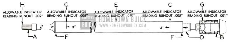
1955 Buick Propeller Shaft Straightening
Use steady pressure and not a shock blow to spring shaft as required to bring run -out points within limits. NOTE: The pinions are machined from centers. All bearing surfaces, gear teeth and spline are held to these centers and no straightening or supports for straightening should be applied to pinion or bearings. This above procedure takes the place of Step 3, 4, & 5 in Sub Paragraph “b” on Page 6-13 of the 1955 Shop Manual.
Leave A Comment
You must be logged in to post a comment.