1955 BUICK AIR CONDITIONING SYSTEM
Three major changes have been made in the 1955 Buick Air Conditioning system. These changes involve the compressor, the condenser, and the air distribution system.
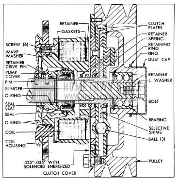
The compressor has been changed from a rotary or vane type to an axial type. The compressor also incorporates an integral solenoid coil for actuating the pulley mounted clutch. See figure 74.
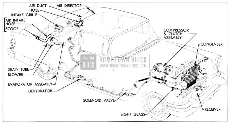
1955 Buick Air Conditioning System Arrangement
In low speed performance, the axial compressor has a marked increase in capacity over the vane type.
The new condenser is still mounted directly ahead of the radiator, but now consists of a series – parallel coil 17 3/16 inches high, 22 1/2 inches wide, and 1 inch deep. See figure 76.
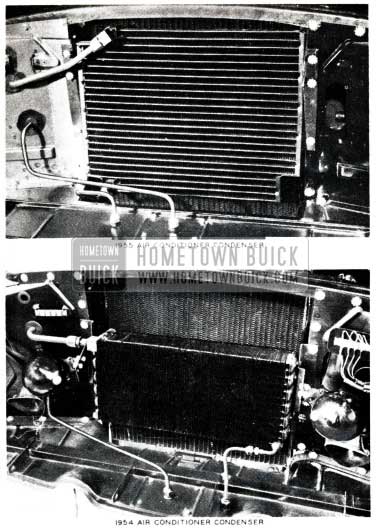
1955 Buick Air Conditioner Condenser
The changes in construction allow a ten pound weight reduction while maintaining the same condensing capacity, and improved engine cooling during idle and low speed operation.
The changes in the air distribution system include the elimination of the headlining air ducts. The same clear plastic conductor tubes will be used in connection with an air director grille at the top to deflect some of the cold air into the rear passenger compartment. See figure 75.
1955 Buick Air Conditioning Overview
With the exception of the foregoing changes the 1955 Buick Air Conditioner installation is essentially the same as in 1954 models.
The service information contained in the 1953-54 Buick Air Conditioner Shop Manual (BPS 7.26) is generally applicable to the 1955 installation except for the compressor service operations.
Any service work that requires breaking a pipe joint should be performed only by mechanics who have been trained in Buick or other automotive air conditioning schools.
Whenever a pipe is disconnected from any unit except the compressor, liquid or vaporized refrigerant will escape unless the proper procedure is used.
NOTE: “Both the suction and discharge valve assemblies are connected together by means of a flat steel plate .(See Figure 77) the entire assembly then is held to the compressor by a single screw located between the two valve bodies and in the center of the steel plate.
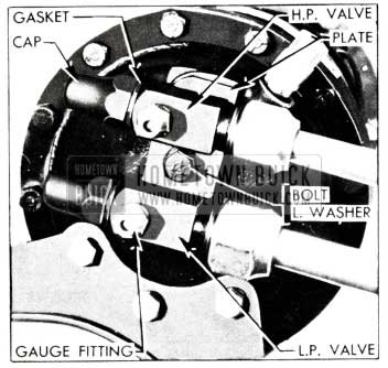
1955 Buick Air Conditioner Steel Plate
When assembling the lines to the valve bodies, it is necessary to hold the body with a wrench to prevent bending the plate. Any bending of the plate will result in a Freon leak past the „O“ ring.
This procedure is in accordance with all other refrigerant joint connections. That is, each joint should be supported with a wrench while tightening the connection. The procedure should be stressed to prevent distortion and damage to all connections.”
REFRIGERANT CHARGE IN 1955 BUICK AIR CONDITIONER SYSTEM
In order to meet various state codes the amount of refrigerant charged into a system will be stamped on the compressor name plate in production. However, whenever a new compressor is installed in the field the number “5” (indicating 5 lbs. of Freon-12 used to charge the system) must be stamped in space provided on name plate as indicated in figure 78.
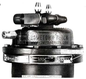
1955 Buick Air Conditioner Refrigerant
This is necessary as all compressors purchased through the Parts Department will have a blank space on name plate for this purpose.
Once the amount of Freon-12 charge has been stamped on the compressor name plate, it will not be necessary to restamp it for any subsequent service operations.
COMPRESSOR SERVICE PROCEDURES
NOTE: Before the engine is raised or lowered for any service operation the high and low pressure valves with lines attached must be disconnected from compressor, as described in subparagraph a, steps 1 through 6.
Removal and Installation of Compressor
- Remove protective caps from gauge fittings of high and low pressure valves on rear end of compressor.
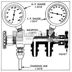
- Connect charging lines of Pressure Gauge Set (See figure 79) to gauge fittings of both valves, with both valves of Manifold 1 5415 closed.
1955 Buick Air Conditioner Compressor Service Procedures
DO NOT PLACE COMPRESSOR IN SUN OR NEAR HEAT BECAUSE IT STILL CONTAINS SOME FREON-12.
- Install compressor by reversing procedure for
- Inspect drive belts and pulley grooves for conditions that might cause slippage. If a belt is cracked, frayed, or oil soaked, or is worn so that it bottoms in pulley grooves replace both belts. Belts are furnished in matched sets only, to insure even tension.
- Adjust drive belts to 1/2″ deflection midway between fan and compressor pulleys.
- Use new O-rings when attaching valve assembly to compressor.
- Before starting compressor make sure that both valves are fully opened.
- After operating compressor for ten minutes at 1750 RPM, leak test around the valve mounting plate.
Replacement of Clutch Parts
NOTE: If compressor is mounted on engine, first remove drive belts and disconnect clutch solenoid wire.
- Remove clip ring and dust cap from pulley hub, then remove bolt, lockwasher and retainer. See Figure 74.
- Remove bolts with lockwashers that attach the clutch cover to rear face of pulley.
- Remove pulley and bearing assembly from shaft using suitable puller. To avoid damaging threaded end of shaft, screw a short bolt into shaft for puller to press against.
- Remove selective shims located between pulley bearing and shoulder of compressor shaft and place these where none will be lost.
- Remove clutch plate and spring assembly from shaft, then remove cover.
- Remove solenoid coil retainer by bending teeth outward with a small screwdriver. Use care to avoid damaging the coil and outer insulator gasket.
- Remove outer insulator gasket, coil, and inner insulator gasket from coil housing. Use thin bladed tools on each side to remove coil and be careful to avoid damaging coil insulation.
- Inspect pulley bearing for wear or tightness. If necessary, replace the bearing, using Ring Pliers J 4245.
NOTE: If pulley hub shows wear caused by rotation of outer race of bearing, replace the pulley.
- Inspect frictional surfaces of clutch plates for dirt, scoring or other damage. If necessary to replace either plate, disassembly by removing the spring retainer ring, using Ring Pliers J 4880.
- Inspect solenoid coil for damaged insulation, frayed or broken leads, or loose terminals. Repair or replace as necessary.
- Install inner (notched) insulator gasket, coil, and outer gasket in coil housing, then install a new coil retainer with teeth pointing outward. Tap each tooth to insure that coil is held firmly in place.
- Place clutch cover over coil housing with ground surface facing outward, then install clutch plate assembly with spring extending into coil housing. One spline on shaft is cut low to locate clutch plates for proper balance.
- Install the original selective shims against the shoulder on shaft, then install pulley. Apply pressure only against inner race when pressing bearing over end of shaft and into firm contact with the shims.
- Install retainer and bolt with lockwasher; tighten bolt securely.
- Attach clutch cover to pulley with bolts and lockwashers.
- Connect solenoid coil leads to 12 volt battery to energize coil, then check clearance between rear clutch plate armature and coil housing, using brass or bronze feeler gauges. This clearance should be .025″-.035″. See Figure 74.
- If clearance is not within specified limits remove pulley and change thickness of the selective shims as required. Shims are available in thicknesses of .015”, .020” and .025″. When clearance is correct install dust cap and clip ring on pulley hub.
Replacement of Shaft Seal
- Remove pulley, clutch plates and solenoid coil (subpar. b, above).
- Remove six Phillips head screws, then carefully pry the coil housing away from compressor body. An oil slinger pressed on the shaft will come out as housing with seal is removed. See Figure 74.
- Press old seal assembly out toward shouldered end of housing, remove O-ring from external and internal grooves then thoroughly clean the seal seat and O-ring grooves.
- Use small screwdriver to force the drive pin retainer out of groove to rest on inner end of seal seat on compressor shaft. Be careful not to mar the oil pump cover.
- Remove drive pin, using needle nose pliers, then remove seal seat from shaft.
- Wipe shaft clean with tissue from seal package. Check shaft spline for burrs or sharp edges, which must be removed with a hard Arkansas stone. Clean shaft again to remove any stone or metal dust.
- Install new O-ring inside the new seal seat and place seat with beveled end down on a piece of oil soaked tissue to protect the polished seating surface. NOTE: Use every precaution to prevent damaging this surface and do not touch it with fingers at any time.
- Place old seal seat over new one and force the drive pin retainer down over new seat, working it down to area between the groove and beveled end.
- Coat O-ring with clean Frigidaire oil and install seat on compressor shaft with drive pin holes aligned, being careful not to damage O-ring on shaft splines.
- Install drive pin and force the retainer into groove over the pin.
- Examine the oil pump cover plate to make certain the small dowel pin is in proper place and flush with outer cover. Also make certain that wave washer is in place.
- Install new internal and external O-rings in grooves of coil housing and coat adjacent areas with clean Frigidaire oil.
- Press new seal assembly squarely into place in coil housing with spring loaded disk toward shouldered rear end of housing. Apply pressure only against the outer flange of seal casing until flange bears against shoulder in housing.
- Install housing on compressor with notch for coil leads in line with pressure relief valve on rear end of compressor. Install six screws and tighten securely.
- Press oil slinger over shaft to allow running clearance with seal casing.
- Install solenoid coil, clutch plates and pulley (subpar. b, above).
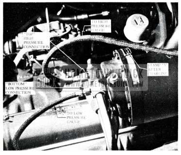
ATTACHING GAUGE LINES TO COMPRESSOR (1955)
Due to the new compressor suction and discharge valve assembly design, Schrader valve gauge fittings are no longer used; therefore, gauge adapters are not needed when making gauge hook-ups. The gauge fittings are sealed off by protective caps and are closed off inside the valve body whenever the service valves are “back-seated” (valve in “wide open” position).
Both gauge connections are located at the rear of the compressor. The upper compressor shut off (service) valve is in the high pressure line, and the lower service valve is in the low pressure line.
CAUTION: All service procedures requiring the handling of Freon should be done with safety goggles on.
Procedure for Attaching Gauge Lines:
With both high and low compressor (service) valves in wide open position and firmly back-seated, remove protective caps and connect pressure gauge set to compressor. NOTE: Make certain that both hand shut off valves on gauges are closed, then turn both compressor valves one complete turn towards closed position to obtain gauge readings.
CAUTION: Do not close compressor service valves completely with compressor in operation.
It is recommended that gauge valves and gauge lines be purged of air before using.
ADDING OIL TO THE AXIAL COMPRESSOR (1955)
In the event that the oil level check (procedure described on page 27, Sub-par. a of the 1953-54 Air Conditioner Manual) shows that the oil level is low, oil should be added as follows:
NOTE: As the oil checking connection at the bottom of the compressor still incorporates a Schrader valve, it will be necessary to use adapter with the oil filler line. (See Figure 80)
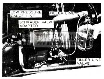
1955 Buick Air Conditioner Schrader Valve Adapter
The filler line may be easily made from an adapter, small petcock and copper tubing.
Procedure for Adding Oil:
With engine and 1955 Buick air conditioning system turned off, hook up gauge set. Be certain both hand shut off (gauge) valves are closed.)
- Remove flare nut and deadhead from Schrader certain that filler line valve (See Figure 81) is “OFF”, then attach filler line and adapter to oil elbow.)
1955 Buick Air Conditioner Low Pressure Gauge
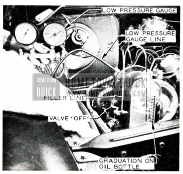
NOTE: The Frigidaire Oil bottle is graduated in 2 oz. increments.
It is suggested that only 4 oz. of oil be added, then an oil level check be made {With air conditioner turned off). Add 4 oz. more if necessary. Repeat oil level check, etc. to prevent over-filling. Due to the restriction caused by the Schrader valve core, the oil enters slowly.
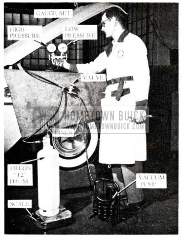
EVACUATING THE SYSTEM
- Attach gauge lines and vacuum pump set-up as shown in Figure 82 and 83.
1955 Buick Air Conditioner Pressure Gauge
1955 Buick Air Conditioner Service
CAUTION: The foregoing steps for hooking up gauge lines should be followed whenever evacuating or charging the system. Firmly back-seating the (service) shut -off valves (First Par.) will prevent escape of Freon when the smaller protective caps are removed from the rear end of compressor.
CHARGING THE SYSTEM
- With the vacuum pump, Freon-12 cylinder and gauge set connected to the compressor as shown in Figure 82 and 83, place the cylinder in a bucket of hot water which does not exceed 125°F.
- CAUTION: Do not heat Freon-12 cylinder above 125 ° F because the fusible safety plug in cylinder valve melts at 157°F and softens at a slightly lower temperature.
- Place cylinder and bucket on a suitable scale and record the total weight.
- Open the low pressure valve on the gauge set. (High pressure valve on gauge set closed)
- Wearing goggles to protect eyes, fully open the Freon-12 cylinder valve and allow Freon-12 vapor to flow into the refrigerating system.
- Operate engine and compressor at slow idling speed until a total of 5 pounds of Freon-12 have been charged into the system.
NOTE: It may be necessary to reheat the water in bucket to maintain required pressure.
- Close both valves on gauge set, close valve on Freon-12 cylinder, and remove cylinder from bucket of water.
- Operate the compressor with engine running at 1750 RPM (using tachometer) and observe general performance of Air Conditioner. If performance is satisfactory, stop the engine.
- With engine off, firmly back-seat both high and low shut-off (service) valves on compressor, then remove gauge lines.
- Replace protective caps over gauge connectors and shut-off valves, then tighten securely.
- Check oil level in compressor as described on page 27 of 1953-1954 Air Conditioner Manual.
KIT INSTALLATIONS 1954 MODELS
NOTE: The following information appeared in the “Buick Parts Product Information” BPPI 55-3, dated January 25, 1955.
The new 1955 Buick Air Conditioner Packages recently released for dealer installations can be used on
1954 Buicks, with the following minor modifications:
- On all 1954 models, the condenser outlet pipe must be pulled ahead approximately 1″ so it will line up with the receiver fitting. The pipe can be easily sprung this distance.
- On the 1954 model 52-72, the template for drilling the fresh air inlet holes in the rear quarter panel must be located by using the trunk lid opening line only, as the back window lower moulding line is different between 1954 and 1955.
- All other installation instructions are the same for 1954 and 1955 models.
AIR CONDITIONER THERMOSTAT AND TEMPERATURE CONTROL CIRCUIT
The 1955 Buick Air Conditioner system uses the same principle for controlling the refrigerating cycle as that used in the past except for the following:
- New solenoid valve is held in a normally closed position by spring pressure instead of held closed electrically as in the past. This design enables the valve to be held closed mechanically instead of electrically during continuous operation of the air conditioner in hot weather.
- A Ranco type thermostat1equipped with silver contact points, replaces the mercury column type previously used. Installation of Ranco type thermostat eliminates the use of relay previously used to control solenoid valve operation. The Ranco thermostat is constructed of a capillary tube and attached bellows filled with sulphur dioxide gas, making it very sensitive to changes in temperature and accordingly cause the expansion or contraction of the bellows. Movement of the bellows controls opening and closing of points through a link which actuates the points. When falling air temperatures reach desired level1for which temperature control is set, the thermostat bellows contracts forcing the link and movable point into contact with a stationary point; thus, completing the circuit to the solenoid valve which opens the by-pass line to stop refrigetation. When rising air temperatures cause the bellows to expand, the connecting link forces the movable point away from the stationary point, breaking the circuit to the solenoid valve. The plunger within the solenoid valve is then forced down by spring pressure, closing the valve to start the refrigeration cycle.
Changing the thermostat calibration to regulate car interior temperature at a level most agreeable to car occupants is obtained through a thermostat selector circuit (formerly called “warming circuit”) which also includes an “anticipator” feature to quicken the action of the thermostat.
Operation of the warming circuit (selector circuit) is essentially the same as in the past, except for the following: With blowers turned on the warming circuit is completed through the rheostat and selector winding to ground whenever the rheostat (temperature control) is rotated clockwise. Rotating temperature control clockwise closes the contact points in ventilation switch, mounted in tandum with rheostat, to supply current to the warming coil. The anticipator circuit is cut in only when the thermostat contact points are closed. See Figure 84.
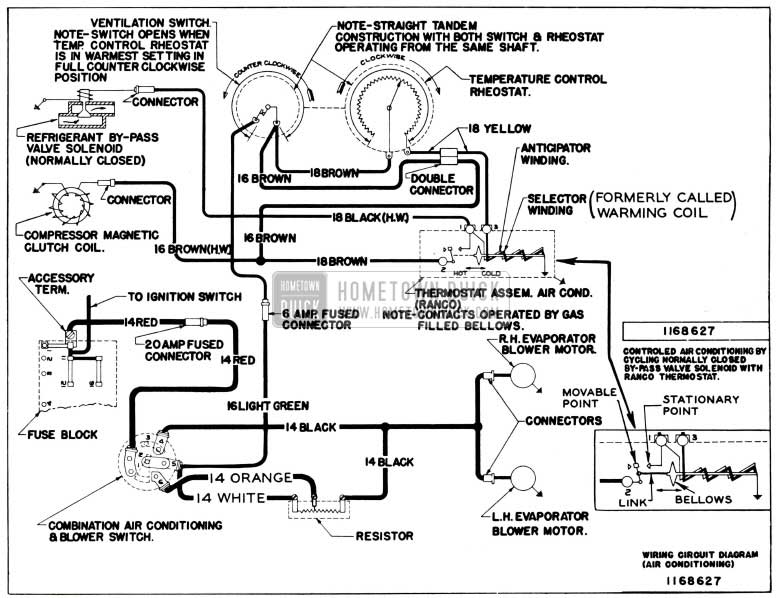
1955 Buick Air Conditioning Wiring Circuit
The new control arrangement provides temperature regulation of car interior at any point between 67° and 80°F.
COMPRESSOR CLUTCH CHANGE
1955
Effective with compressor Serial No. 16XB275, the following changes were made in the compressor clutch assembly:
The angle of tear drop depression on both clutch plates has been changed, and the clutch activating coil has been redesigned. These changes provide an improvement in overall clutch operation.
All clutch plates installed in compressors after Serial No. 16XB275 will have the improved design, and can be identified by a letter “0” stamped on the inner face of each clutch plate. The new coil is identified by an orange ground lead (previously black).
Whenever it becomes necessary to replace either of the two old type clutch plates (plates prior to Serial No. 16XB275, both old plates should be replaced with the new type and the new coil (with orange ground lead) should also be installed. NOTE: The new coil should always be used in conjunction with the new type clutch plates.
Also, whenever the clutch is being serviced and inspection of parts reveals that the nylon activating balls require replacements, be certain to use balls Gr. 9.188 Part No. 5917481 which are specified only for 1955 axial compressors.
Listed below are group and part numbers of the new clutch plates and coil.
Gr. 9.186 – S912343 – Coil-Compressor Clutch Actuating.
Gr. 9.188 – 5912346 – Plate and Counter Weight Compressor Clutch.
Gr. 9.188 – 5912345 – Plate and Armature-Compressor Clutch.
COMPRESSOR CLUTCH ACTUATING COIL RETAINING KIT
Effective with the production of compressor Serial No. 44XB-714 on March 10, 1955, a new method of retaining the clutch actuating coil has been incorporated. Since this new method of coil retention is more positive, our Engineering Department has also recommended its use for field service.
The Parts Department is making available a service kit, Group No. 9.186, Part No. 5876681, containing the parts as shown in Figure 85.
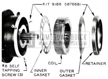
1955 Buick Compressor Clutch Actuating Coil Retaining Kit
It is recommended that in cases where the first type retainer has failed, or whenever it is necessary to remove the clutch and pulley assembly, this new retainer kit be installed by following the procedure listed as follows
- Remove the compressor assembly as described in Section 11-D, par. 11-8 of the 1955 Shop Manual.
- Remove the clutch pulley assembly.
- Remove the coil retainer and insulator gasket (discard both).
- Disconnect coil leads and remove coil.
- Remove inner insulating gasket (discard).
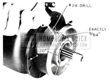
- Center Punch and drill (using a No. 24 drill) in the seal housing as indicated in Figure 86.
1955 Buick Compressor Clutch Seal Housing
The first hole should be directly opposite the coil lead port; the .two remaining holes should located one on either side and approximately 120° from the first. The holes must be located 9/64” back from the face of the seal housing as indicated. Thoroughly clean housing to protect coil and clutch parts from shavings and other foreign material.
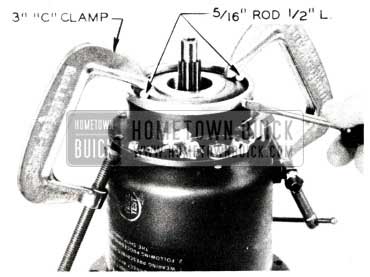
1955 Buick Compressor Clutch Seal Housing Clamps
NOISY BUICK AIR CONDITIONER COMPRESSOR
1955 Model
At the present time Engineering advises that the noisy air conditioning compressors could be caused by either of the following.
- A loose clutch actuating coil retainer. This internal tooth retainer is held in position only by pressure exerted by the teeth. When the retainer comes loose, it makes contact with the revolving clutch plate, causing a scraping noise during all speeds of the compressor operation.
- Liquid Freon 12 passing through the compressor when the engine is idling will cause a slight noise; however, this noise is characteristic of our 1955 Buick air conditioner system. It is usually present when temperatures remain in lower 70’s and when the engine is idling. It will have to be explained to the owner that it is a normal condition and can be expected at such temperatures.
1955 BUICK AIR CONDITIONER TEST DATA
The following functional testing data is to be used when checking 1955 air conditioner equipped cars. This data replaces any previous information governing functional test for 1955 models.
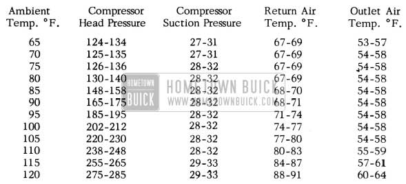
1955 Buick Air Conditioner Test Data
Car conditions for functional test are:
- No sun load
- Cars stationary with windows closed, trunk closed, doors closed and hood open.
- Outside air intake valves closed.
- Shroud ventilation valves closed.
- Forced air supply over condenser. (Engine running) (Using electric fan)
- The air conditioning rheostat set for maximum cooling.
NOTE: Outside air intake valves are to be left closed after functional tests during the winter months. Conversely, these valves are to be opened after test during summer months.
Data to be recorded during each test is:
- Ambient air temperature °F.
- Conductor tube outlet air temperature °F.
- Left return air grille air temperature °F.
- Compressor suction pressure PSIG.
- Compressor head pressure PSIG.
The above recorded data should be within the following limits for corresponding ambient temperatures.
To test units in ambient temperatures of 70° or lower, it is necessary to operate the car heater to raise the in-car temperature above the ambient and actuating temperature of the thermostat.
Under higher ambient temperatures, approximately 10-15 minutes operational time is required for recorded data to be within the above limits. Also, 15-20 minutes operational time is required to reach the lower limits.
Following is a comparison between the 1954 and 1955 air conditioner compressor and condenser.
COMPRESSOR COMPARISON
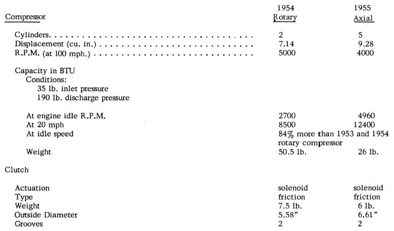
1955 Buick Air Conditioner Compressor Comparison
CONDENSER COMPARISON
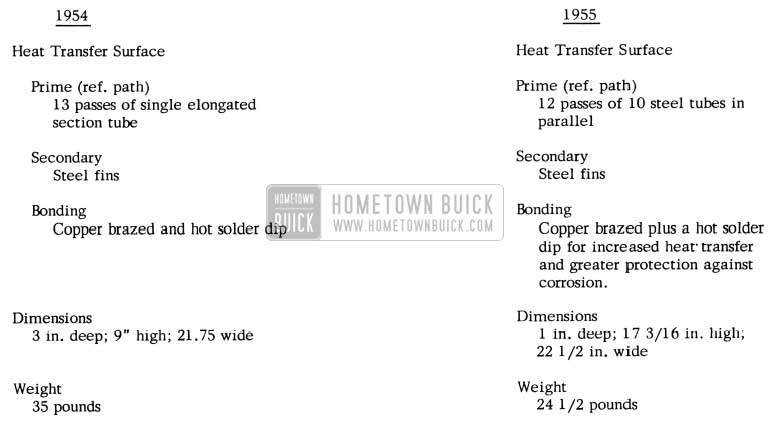
1955 Buick Air Conditioner Condenser Comparison
EVACUATION OF AIR CONDITIONER
Self Evacuation – 1955 Buick Air Conditioner
In cases where it becomes necessary to evacuate the Air Conditioner and it is impossible to obtain the proper pump for this evacuation, the following procedure may be followed.
- Hook up gauges, lines and Freon 12 Cylinder as shown in Figures 82 and 83 on Page 90, but substitute a bottle or other suitable container in place of the vacuum pump. This container is to catch the evacuated oil so it may be measured and a like amount of clean oil replaced. Be sure that the fitting on the discharge valve is open to the compressor with no restrictions from valve closures, Schrader cores, caps, or plugs, in the attached line before starting the engine.
- Leaving low pressure gauge valve tightly closed, carefully open the high pressure gauge valve and hand shut-off valve (vacuum line valve), being careful to avoid any accidental discharge of liquid Freon 12.
- Start engine and set at low idle (450rpm) and tum Air Conditioner switches on “Fast” and “Max. cooling”. Maintain engine speed at slow idle at all times during evacuation. Close high pressure compressor service valve (tum all the way clockwise).
- Operate system at low idle for 5 minutes then tum off engine and air conditioner and close hand shut-off valve immediately. If system holds 25″ vacuum for 10 minutes proceed to Step 5; if not, locate and correct leak and repeat steps 2, 3 and 4.
- Close high pressure gauge valve, open low pressure gauge valve, and charge system with Freon at cylinder pressure. Then evacuate again as in steps 1, 2, 3, and 4 for 5 minutes.
- Again close high pressure gauge valve, and open low pressure gauge valve and then complete charging with 5# of Freon as outlined on Page 90 of this booklet.
- Following the procedure outlined on page 89& 90 replace an amount of clean (Frigidaire 525 Viscosity) compressor oil equal to that discharged in steps 4 & 5. Then perform oil level check.
- Remove gauge lines and oil charging lines, cap the fittings, and check the performance of the unit.
CAUTION: Under no circumstances should it be assumed that the foregoing procedure will remove water from the system. Where a leak has occurred and there is a possibility that the system has been operated in a discharged condition, it is essential that the dehydrator be changed.
PERIODIC AIR CONDITIONER CHECKS In order to keep Buick Air Conditioners operating at peak efficiency and to maintain a high degree of owner satisfaction, it is strongly recommended that the following points be checked every thousand miles or sooner if necessary. Items indicated by asterisks may be checked by the Service Adviser in the presence of the owner so that any additional service required may be brought to the owner’s attention.
- Check radiator and condenser cores to see that the air passages are not obstructed with bugs, dirt, etc.
- Check evaporator air filter to be certain that this is not obstructed with dirt, lint, etc. This may be done by looking down through the return air grilles on the parcel shelf. It may be necessary to use a mirror and flash light in order to make this check on 1954 and 1955 jobs. If the filter is dirty, clean or replace as necessary.
- Check sight-glass with unit in operation to make certain that the Freon charge is sufficient for maximum cooling.
- Check lower ends of evaporator drain tubes to make certain that they are not kinked or stuck shut with undercoating.
The foregoing are the recommendations of our Engineering Department who feel that attention given to the above items will reduce air conditioner troubles to a minimum. It is also suggested that these be the first items checked on an Air Conditioner complaint.
WIRING HARNESS INSTALLATION
1955 Buick Air Conditioner Kit
Supplementing air conditioner kit installation instructions, it has been found that removal of defroster duct and bowden wire for wiring harness installation is unnecessary as the harness may be installed by running a wire through the cowl over the defroster duct and pulling compressor, resistor and solenoid wire through the cowl panel. Using this method will save time and effort.
AIR CONDITIONER FLEXIBLE PIPES
The flexible pipe portion of the Air Conditioning Compressor Suction and Discharge Pipes are now released as separate service items. This will allow the replacement of only the flexible portion of the Suction and Discharge Pipes when only this part of the pipe is damaged.
Following are the new parts:
Group 9.238 – 5883239 – Pipe -Suction- Flexible 1953 52-56R-72-76R
Group 9.238 -1165138 – Pipe-Suction-Flexible 1954 410-61-52 -56R-72-76R;
Group 9.225 – 5883240- Pipe-Discharge-Flexible 1953 52 -56R-72- 76R
Group 9.225 – 1166382- Pipe-Discharge-Flexible 1954 41D-61-52-56R -72-76R; 1955 41-43-46R-61-63-66R-52-56R-72-76R
NEW DEHYDRATOR AND RECEIVER ASSEMBLY
1955
A new combination dehydrator and receiver assembly has gone into production making possible the elimination of the dehydrator assembly previously used. The refrigerant pipes have been extended to compensate for elimination of the dehydrator assembly.
If, for any reason, the refrigerant system is exposed to atmosphere for an extended length of time, the complete dehydrator and receiver assembly Gr.9.195 Part #1169494 must be replaced.
INSUFFICIENT COOLING
We have received a few reports where air conditioner did not cool properly because of a number of small plastic -like beads lodged in the lines and various other parts of the air conditioner. Although this is certainly not desirable it is not a serious problem. These little plastic-like (sova beads) are part of the dehydrator and should the screen-like retainer fail, it will allow these particles to travel in the line along with the Freon.
When this condition exists it will be necessary to clean out all components, making certain that all are free of the dehydrator material, and replace the dehydrator with a new one. Then recharge system and check operation.
AIR CONDITIONER COMPRESSOR EXCHANGE POLICY & WARRANTY
As announced in Special Service Letter, Dealer No. 152, the warranty on 1953 air conditioner compressors has been extended through December, 1955.
The warranty on 1954 and 1955 model compressors, however, expires after one year of service.
When the original compressor fails after expiration of the one -year warranty period, it will be necessary for the owner to purchase a new compressor under an exchange plan. These exchange compressors are available through your Parts Warehouse.
The warranty on the new compressor purchased under the exchange plan is for 90 days from the date of installation or 4000 miles, whichever occurs first.
The amount of credit under the exchange plan will be $50 for each compressor, plus the transportation cost of returning the old compressor by truck to your normal shipping warehouse. In order to obtain the $50 exchange credit, the returned compressor must be a sealed unit and undamaged. Also it is to be returned in the container in which the replacement unit was received, since these containers are especially constructed to provide the necessary protection.
When returning compressors to your warehouse they are to be listed on an Application for Authorization to Return New Material (Form WH-7) and shipped by truck, prepaid. Form WH-7 will be filled out in the normal manner, showing ”Exchange Plan’ ‘ as the reason for return. It will not be necessary to show the date received or the order number.
The new exchange compressor is warranted for 90 days or 4000 miles. Therefore, should it require service of any kind due to defective material or workmanship during this period, it should be provided on a no-charge basis and an AFA submitted to your zone office to cover the cost of repairs.
I wonder if GM made money on air conditioning in early years.