1955 BUICK BODY STYLES
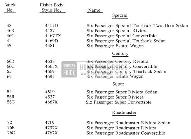
1955 Buick Body Styles
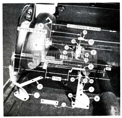
PAINT & TRIM COMBINATIONS
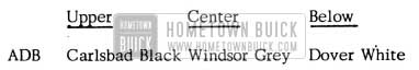
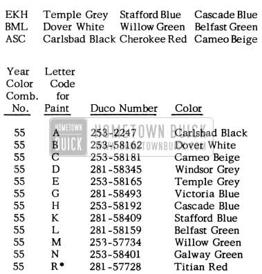
1955 BUICK COLOR COMBINATION
Alphabet Code Letters designate colors which are available for solid, two-tone, or three-tone color combinations. The first alphabet letter designates the upper color, the 2nd alphabet letter denotes the center color, and the 3rd alphabet letter denotes color below molding, i.e., Comb. AAA would be all “Black”; combination AAB would be Black above molding – Dover White below molding; and ADB would be Upper – Black, Center – Windsor Grey, and below molding – Dover White.
The 3-tone Color Combinations will be available ONLY in the following color combinations.
1955 BUICK TRIM COMBINATIONS
1955 Buick Triple Tone Color Combination
1955 Buick Paint Combinations
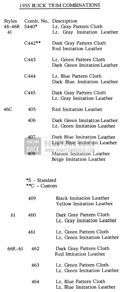
1955 Buick Trim Combinations
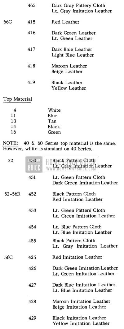
1955 Buick Interior Trim Combinations
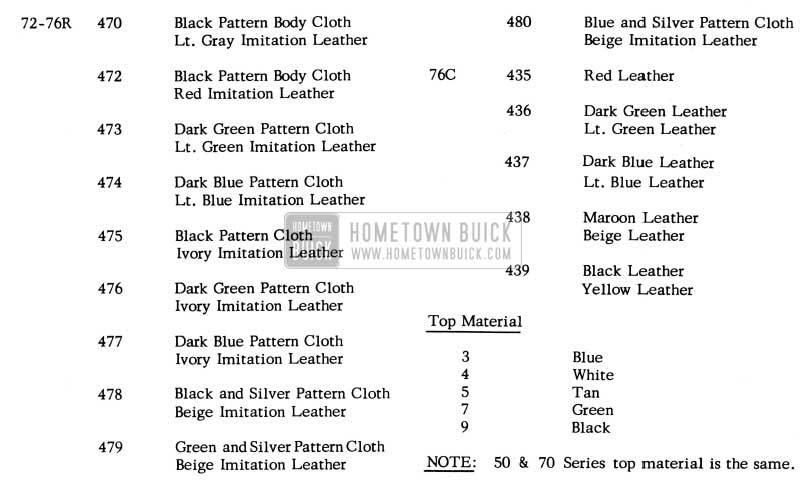
1955 Buick Interior Combinations
1955 BUICK OPTIONAL EQUIPMENT CHART
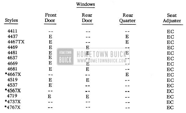
1955 Buick Optional Equipment Overview
E -Electric
EC – Electric Combination (Horizontal & Vertical)
* – Electric Windows and Electric Horizontal Seat Adjuster – Standard Equipment.
4519-4719, 4537-4437-67TX-69, 4637-69 Styles – two window option or four window option available with or without electric seat option.
LIFT GATE HINGE CORRECTION
1954 ESTATE WAGONS
A structural weakness has occurred at the Hinges of the Lift Gate on 1954 Estate Wagons.
The hinges can be reinforced by taking the following corrective steps:
- Remove the entire Lift Gate from the Rear Body Opening.
- Loosen and remove the screws which anchor the Lift Gate to the Side Supports.
- Loosen and remove the 1/4″ bolts which anchor the Lift Gate to the Hinges at the top.
- Place the Lift Gate (Outside face down) on a work table or bench.
- Disassemble the Lift Gate.
- Loosen and remove the screws which hold the Garnish Moulding in place.
- Remove the Garnish Moulding.
- Remove the Glass and Rubber Channel.
- Install Reinforcements – See Figure 88.
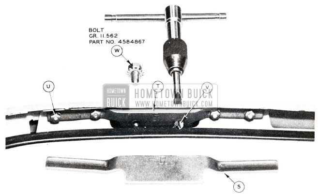
1955 Buick Lift Gate Hinge
- Select Reinforcement Stamped “R” (shown) for R.H. Side and Reinforcement stamped “L” for L.H. Side (Ionia Mfg. Co. Part Nos. 81594 Rt. & 81595 Lt.).
- Locate each reinforcement by fitting over the 1/8” plate on inner surface of Lift Gate Frame and clamp in place.
- (a) Drill four clearance holes (3/16 dia.) through Frame and Reinforcement at each Reinforcement for No.8 screws. (b) Insert No. 8 screws and anchor with No.8 nuts.
- Optional anchorage – Weld each reinforcement to Lift Gate Frame instead of using No. 8 screws and nuts.
- Drill (.272 dia. – Letter I) and tap for 5/16-24 thread through each plate and Reinforcement – two holes at the existing 1/4″ bolt holes.
- Install Glass and Rubber Channel, applying 3M Auto Body Sealer around the Rubber-fitting area of the Lift Gate Frame.
- Install the Garnish Moulding and anchor with the existing screws.
- See Item W of Figure 88. Anchor Lift Gate to Hinges with four 5/16-24 bolt and washer Assemblies (Part No. 4584867) which replace the original 1/4″ bolts and washers.
- Anchor Lift Gate to Side Supports with the existing screws.
ELECTRIC WINDOW REGULATORS CHANGE
In order to improve the shock characteristics and improve the coupling life, the pinion and gears in the Door and Quarter Window Electric Regulator Motors have been revised by replacing the present rubber coupling with a new “Unistress” rubber coupling. These changes affect both the 12 tooth and 24 tooth pinion and gears presently used.
The new design “Unistress” gear coupling incorporates a rubber sealing lip which eliminates the need for the metal dust cover presently used.
At the present time, two (2) pairs of motor assemblies are released for replacements; one (1) pair of motors with 12 tooth pinion and gear for use on the Front and Rear Door Windows and the Rear Quarter Windows on Rivieras and one (1) pair of motors with 24 tooth pinion and gear for use on the Rear Quarter Windows of convertibles. Since the new Pinion and Gears are readily assembled to the worm gear in the motor, motor assemblies less the pinion and gear are to be released for service replacements. This can be accomplished since the motors, less the gears, are interchangeable and will eliminate one (1) pair of motors. These new motors, less the gears, will be used for all service replacements of the present motors, with gears, when stock on hand is exhausted.
The new 12 tooth Gear Package, which will include gears with the unistress coupling, will be used for all service replacements of the old package. Both the old and new 24 tooth Gear Packages will be maintained for service as the new package cannot be used with an old regulator due to a change which was made in the regulator at the time the “Unistress” coupling was added to the motor.
Following are the parts involved in the above change:
Group 10.783 -5047832 – Motor-Door Window Electric (12 tooth)
Group 11.041 – 5047834 – Motor-Rear Quarter Window Electric (24 tooth)
To be replaced by:
Group 10.783 – 4900218 – Motor-Door and Quarter Window Electric (Less Gear)
Group 10.783 – 5047833- Motor-Door Window Electric (12 tooth)
Group 11.041 – 5047835 -Motor-Rear Quarter Window Electric (24 tooth)
To be replaced by:
Group 10.783- 4900219 – Motor-Door and Quarter Window Electric (Less Gear)
Group 10.783 – 5097959 – Package-Electric Window Regulator Motor Pinion and Gear
To be replaced by:
Group 10.783 – 4900085- Package-Electric Window Regulator Motor Pinion and Gear.
Group 11.041 – 5097960 – Package-Rear Quarter Electric Window Regulator Motor Pinion and Gear
1954-56C-76C; 1955-46C-66C-56C-76C Up to Body
Note: For use with regulators date stamped 5-15-55 or before.
Group 11.041 – 5099592 – Package-Rear Quarter Electric Window Regulator Motor Pinion and Gear (Unistress)
1955-46C-66C-56C-76C after body; 1956-46C-66C-56C -76C
Note: For use with regulators date stamped 5-16-55 or later.
PAINT REFINISHING INFORMATION
1955 MODELS
With the current trends towards almost limitless variety of multiple paint color combinations, the following important factors should be considered when refinishing. The factory finish on G.M. automobile is applied under controlled conditions which provide the maximum film thickness that can be built-up on a steel panel. Whenever re-finishing in another color (or the same color), it is imperative that the total film thickness does not exceed the original paint thickness, which, under controlled conditions, has approx. .005 absolute maximum total thickness from the base of the metal.
We would like to point out that merely “scuffing” the original color coats before re-finishing or two toning can result in a film thickness which is too great to withstand the normal expansion and contraction of the panels and of the finish itself. Conditions commonly experienced with an excessive film thickness are: cracking, checking, peeling, alligatoring, etc.
In addition, if moldings are not removed, careless spray technique can cause “bridging” along the molding.
When refinishing panels that have paint checks or cracks, the following precautions should be observed to prevent excessive build-up of paint.
- The original color coat should be sanded down or stripped with lacquer removing solvent (Duco No. 39012) until all traces of paint cracks or checks are removed.
- To minimize the number of top coats required, the DuPont white (Duco No. 233-9607) “Make ready” primer-sealer should be used to seal old color coats as it provides maximum sealing and adhesion, and produces a uniform gloss and hold-out of color coats. The “Make-Ready” primer-sealer may also be tinted with 5% Duco color if desired.
- lf the original color is a “bleeder” and is not entirely removed, a sealer must be applied before application of the new color coat. In this case, DuPont “Bleederseal” No. 233-2184 should be used to seal the old color rather than the “Make-Ready” sealer.
NEW PAINT COLORS
1955
In order that your records may be complete, we are listing the refinish ” Duco” lacquer stock number for the five new 1955 Buick spring colors as follows:
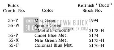
1955 Buick Paint Colors
PAINT STRIPPING OPERATION
In any Body or Chassis refinishing operation where it becomes necessary to strip the old paint and repaint with the same color and time is not already included in the operation, stripping time should be allowed at a rate of 50% of the original refinishing time. The amount of paint remover used should be approximately the same as that of paint used. For example, if it takes 2 hours and
1 qt. of paint to refinish a panel, 1 hour and 1 qt. of remover would be allowed, in addition, for stripping. In all stripping operations, the time is adequate to strip the paint down to the bare metal should this be necessary. However, the condition of the painted surface and the paint itself should be considered before this is done. Time is allowed only for masking, not the removal, of moldings during any refinishing operation.
UNDERCOATING BUICK CARS
It has been brought to our attention that some service personnel are carelessly applying undercoating in certain areas where undercoating should not be applied.
Since this material is inflammable when wet, extreme caution should be exercised when applying undercoat to the under parts of a car.
DO NOT PUT UNDERCOATING on muffler, exhaust and tail pipes, balancers, brake and wheel cylinder, air conditioner parts, rubber hoses, or any moving parts such as shift and brake linkage pipe fitting, etc.
Undercoating should only be applied to the following parts:
Complete body floor pan, under all fender surfaces, bottom of rocker panel (Note: Do not plug drain holes), and bumper gravel shields. Make sure all sheet metal joints are sealed, light coat permissable on gas tank; however, upper end of filler neck and cap to be avoided.
NOTE: Any overspray on moving parts, pipe fitting, fan belts, exhaust system, air conditioner parts, etc. must be removed.
FLOOR PAN OIL CANNING
1955 Buick 43, 63
On some early production special sedan style bodies, an “oil-canning” condition has been noted in the floor pan just forward of the rear seat. Engineering changes have now been made to correct the condition in production.
In the event this condition is encountered, it can be corrected by turning back the floor carpet and forming depressions or beads in the floor pan with a hammer and swage as required in the area where the metal is ”oil-canning’ ‘. The depressions formed by the swaging operation can be filled by cementing a piece of deadener material in the depression.
SEAT TRIM DAMAGE
We have been advised by Fisher Body Service that certain types of clear plastic seat covers currently being sold are harmful to surface finishes of genuine leather and coated fabrics.
Buick Motor Division cannot be responsible for trim material damage through the use of such seat cover material.
SPLIT SEAM ON SEAT TRIM
PROCEDURE FOR CORRECTING SPLIT SEAM ON FRONT SEAT CUSHION
1955 – 50 and 70 SERIES COUPE
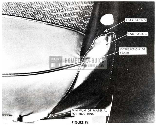
If a split seam occurs at either rear outer corner of the front seat cushion trim, as shown in Figure 6, the following procedure may be used to correct the condition.
- Remove seat side panel.
- Remove hog ring attaching end facing to side of seat frame. See Figure 89.
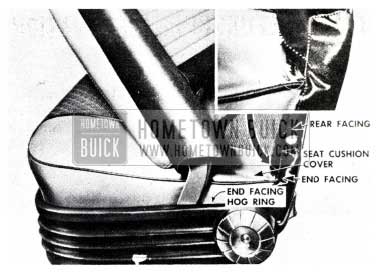
1955 Buick Split Seam on Seat Trim
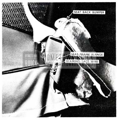
1955 Buick Seat Back Bumper
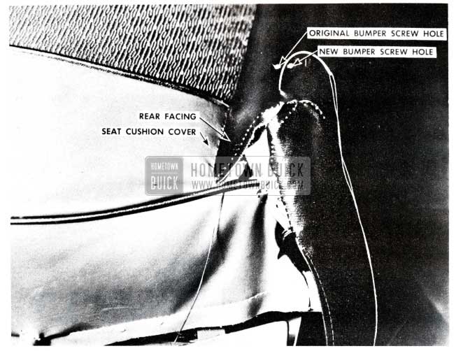
1955 Buick Seat Cushion Cover
Material should overlap original seams by at least 1/8”. If additional rear facing material is required, it can be obtained by removing the hog rings attaching the bottom rear facing beneath the seat and rotating the material forward.
1955 Buick Seat Rear Facing
REMOVAL OF PROTECTIVE COATING
SERVICE REPLACEMENT PANELS COATED WITH “METAL WRAP”
To avoid the possibility of paint failures on replacement service panels which are coated with a transparent protective coating called “Metal Wrap”, we recommend the following procedure be followed very carefully:
- Completely remove the “Metal Wrap” protective coating from the entire panel with mineral spirits, kerosene or enamel reducer and clean rags. Be especially certain that all hemming flanges, corners, etc., are cleaned thoroughly.
- Wipe the entire panel with a solvent cleaner, such as “Prep-Sol”, “Pre-Kleano and Wax Remover” or their equivalent.
- Lightly sand the bare metal with 320 sandpaper.
- Wash the panel with a metal conditioner, such as ”Metalprep”, ”Metal Conditioner”, “Dioxidine” or any other equivalent. Follow the manufacturer’s directions for applying the specific material used.
NOTE: After completing Step No. 4, the metal surfaces to be painted should not be touched with the hands before the primer coat is applied. lf the panel is not primed shortly after cleaning, Step No. 4 should be repeated before priming
- The surface is now ready to be painted in the usual manner.
CLEANING PROCEDURE WHITE VINYL TOP MATERIAL
All 1955 Convertibles
Generally, soilage can be removed with art gum or crude rubber. lf dirt is heavily embedded in the fabric, the top should be thoroughly brushed with a whisk broom. In this brushing, a minimum of pressure should be applied to those areas of the assembly which cover metal bows of the top structure; heavy abrasion will disturb the surface of the material appreciably, causing an unsightly appearance. After brushing, the top should be washed thoroughly with a neutral soap suds and lukewarm water; a cloth or brush with soft bristles should be used. Generous quantities of clear water should then be applied over the surface to remove any trace of soap which might remain.
After cleaning as above, if soilage persists, the following procedure can be used on white vinyl coated folding top material only.
Rinse the whole top and body of the car with water. Then apply a limited amount of Kar-Kleen to the top and sprinkle it liberally with a good bleach-free foaming type cleanser, in an area of approximately two square feet. Mix the Kar-Kleen and cleanser until a paste is formed by scrubbing the top with a small hand brush having soft or nylon bristles. Again wet down the painted portion of the car, then rinse the top off thoroughly. Apply additional application of Kar-Kleen and cleanser if necessary to get the top clean. This should not be necessary more than two or three times. After the whole top has been cleaned in the above manner, rinse the top generously with water to remove all traces of residue cleanser. NOTE: Buick Kar-Kleen acts as a lubricant and prevents the cleanser from imbedding into the top material.
CAUTION: Care should be exercised to keep the foamed mixture from running down across the body finish. If the paint film has accumulated road grime and oxidation on it, the cleanser and Kar-Kleen can cause streaks if allowed to run down and dry. The end result is the same as any detergent which may be applied to paint.
Volatile and other clear cleaners, naphtha, gasoline or household cleansing and bleaching agents should never be used.
After cleaning, always be sure that the top is thoroughly dry before it is lowered. Folding the top while it is still wet or damp may cause mildew and unsightly wrinkles.
If this procedure is followed, the replacement of tops in the field due to inability to clean them satisfactorily should be eliminated.
INTERCHANGEABLITY
OF REAR COMPARTMENT LIDS
1954-1955 MODELS
In order to reduce service parts inventory, Interchangeable Rear Compartment Lids, Group 12.181, have been developed and released. These Lids will have the 1955 Lid Lock Cylinder Hole punched in them. When using them on 1954 models, the Lock Cylinder Hole must be enlarged to accomodate the 1954 Lock Cylinder. None of the Lids will include holes for attaching the Rear Compartment Lid Emblems, or the Rear Compartment Lid Handles (1955-70 only). These holes must be drilled using the illustrations for locating. See Figures 93 and 94.
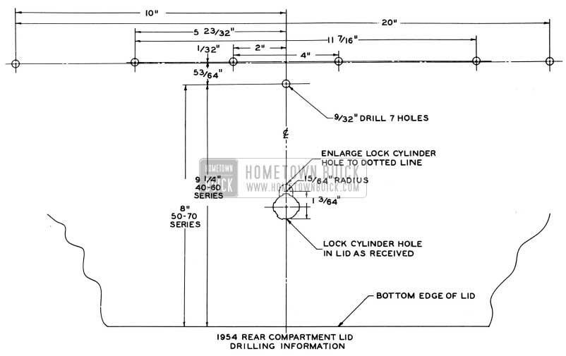
1955 Buick Rear Compartment Lid – 1954
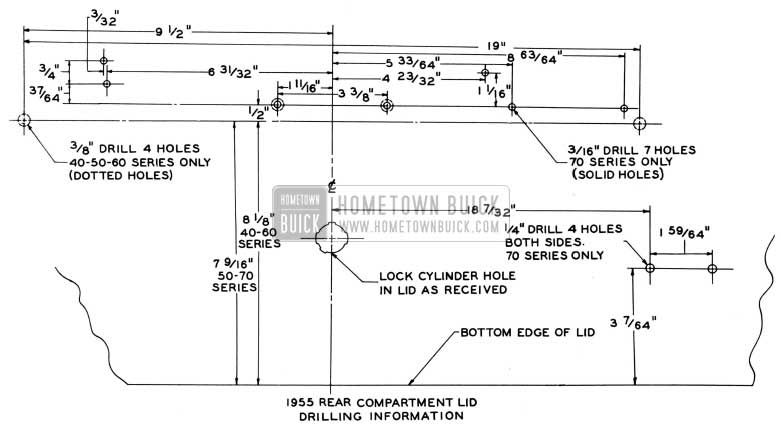
1955 Buick Rear Compartment Lid – 1955
Following are the replacements which will be made:
Group 12.181 – 4630817 – Lid, Rear Compartment 1954-410-480-61
Group 12.181 – 4659968 – Lid, Rear Compartment 1955-41-48-61
The above Parts will be replaced by:
Group 12.181 – 4241810 – Lid, Rear Compartment
Group 12.181 – 4632025 – Lid, Rear Compartment 1954 -46R -66R
Group 12.181 – 4635697 -Lid, Rear Compartment 1954-46C-66C
Group 12.181 – 4659952 – Lid, Rear Compartment 1955-46R -66R
Group 12.181 – 4659953 – Lid, Rear Compartment 1955-46C-66C
The above Parts will be replaced by:
Group 12.181 – 4241879 – Lid, Rear Compartment
Group 12.181 – 4619106 -Lid, Rear Compartment 1954-52-72
Group 12.181 – 4656403 – Lid, Rear Compartment 1955-52
Group 12.181 – 4662772 – Lid, Rear Compartment 1955-72
The above Parts will be replaced by:
Group 12.181 – 4244566 – Lid, Rear Compartment
Group 12.181 – 4621312 – Lid, Rear Compartment 1954-56C-56R-76C-76R
Group 12 .181 – 4656461 – Lid, Rear Compartment 1955-56R-56C
Group 12.181 – 4662773 – Lid, Rear Compartment 1955-76R-76C
The above Parts will be replaced by:
Group 12.181 – 4244563 – Lid, Rear Compartment
DOOR HANDLE REMOVAL & INSTALLATION
1955 – 52-72 SERIES
It has been determined that the door outside handles on the 1955 “52” and “72” series may be removed without detaching the window lower sash channel cam from the window, as described on pages 5 and 6 of the 1955 Fisher Body Service News No.1.
The revised removal and installation procedure is described below and should be suitably entered in the Service’ News to maintain an accurate reference.
REMOVAL
- Raise door window to the full “up” position and remove door window garnish molding assembly and door trim pad.
- Insert a magnetized screw driver through lock access hole and remove handle attaching screw “B”. Use extreme care not to drop screw between door panels.
NOTE: A long, narrow screw driver or similar tool inserted through the lock access hole can be used to hold up the sash channel weatherstrip to prevent interference when removing screw.
- Remove the handle attaching screw, indicated at “A”, and remove handle and gasket from the door.
NOTE: After the outside handle assembly is removed from the door, the lock cylinder assembly can be removed from the handle in the same manner as on the past model.
INSTALLATION
- Cock lock bolt by pushing to “up” position.
- Depress push button on door handle, then assembly handle and gasket to door. When the push button shaft of the door lock cylinder is properly engaged in door lock, lock bolt will snap down.
- Install handle attaching screw ‘ ‘ A”, then screw “B” and check push button action of handle.
- Reinstall door trim pad and hardware parts
REAR SEAT CONVERSION
1955 Buick Estate Wagon
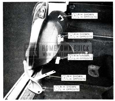
The following information is offered for converting the full rear seat of the 1955 Estate Wagon to the divided rear seat.
- Remove Full Rear Seat Assemblies so that only Items ”1” to ” 5” inclusive remain on both sides as indicated in Figure 95.
1955 Buick Rear Seat Conversion
1955 Buick Rear Seat Conversion Instruction
“6” (a) Locate across car to Dimension “B”. (b) Locate fore and aft by aligning pin with holes in Item ”1”, right and left. (c) Drill two holes 3/8″ diameter in floor pan and anchor with two of Item ”14” to Item ”11” placed underneath floor pan.
“7” (a) Place on top of floor pan and anchor with one of Item “14”. (b) Drill two holes 3/8” diameter in floor pan and anchor with two of Item “15”.
”8” (a) Locate across car to Dimension ” D”. (b) Locate fore and aft by aligning pin with holes in Item “3”, right and left. (c) Drill four holes 3/8” diameter in floor riser. (d) Drill two additional holes 3/8″ diameter in floor riser, 1 1/4:’ to right and 1-1/4″ to left of lower two holes. (e) Cut notch in floor riser deadener and replace, if necessary, with two of Item”13″. (f) Anchor with four of Item “14” and two of Item “19” to two of Item “12” placed underneath floor riser.
“9” (a) Locate across car 7-5/8″ from Item “4” right hand. (b) Locate fore and aft so that Plane ”E” coincides with Item ” 4′ ‘, right and left. (c) Drill four holes .136″ diameter (#29) in floor pan and anchor with four of Item “16”.
“10”(a) Locate as required by Item “5” (R&L) and Divided Rear Seat Back, right and left (see Items A&E – Page 23A – Parts Book). (b) Drill three holes .161″ diameter (#20) in floor pan and anchor with three of Item “17”.
“18” Insert four in grooves of pins on Items “6” and “8” after installing Divided Rear Seat Back and Cushion, Rights and Lefts (see Items A,E,G and M-Page 23A Parts Book).
Gr.15.033-81834 Rt.cushion-14.998-81842 Rt. Back 15.033-81835 Lt.cushion-14.998-81843 Lt. Back
“20” Not shown on Figure (see Item H-Page 23A-Parts Book). (a) Locate two on floor as required by leg and bracket of Divided Rear Seat Cushion, Right and Left. (b) Drill four holes .136″ diameter (#29) in floor and anchor with four of Item “21” (not shown on Figure).
- Identification of Items required for conversion exclusive of Divided Rear Seat Back and Cushion, Rights and Lefts.
- Ionia Mfg. Company Part Numbers: Order from Ionia Mfg. Co., Ionia, Michigan.
“6” Gr. 11.620-81769 Hinge (Item L-Page 23AParts Book)-1 Reqd.
“7” Supt. (Included in Hinge Assy.-Item L)
“8” 11.609-81773 Hinge (Item C-Page 23AParts Book) -1 Reqd.
“9” 11.621-81777 Supt. (Item B-Page 23AParts Book)-1 Reqd.
“10” 11.623-81784 Stop (Item D-Page 23AParts Book)-1 Reqd.
“11” N.G.N. -81256 Reinf. (Item 1-Page 23A- Parts Book)- 1 Reqd.
“12” N.G.N.-81781 Reinf.-2 Reqd. “13” N.G.N.-81772 Shim -2 Reqd.
“20” 11.615-81393 Bumper (Item H-Page 23AParts Book)-2 Reqd.
- Standard Parts Available Locally
“14” F.H. Mach. Scr. 5/16-18 x 1-1/8-7 Reqd. Lock Washer 5/16-7 Reqd. Hexagon Nut 5/16 -18-7 Reqd.
“15” Hex. Hd. Bolt 5/16 – 18 x 1-2 Reqd. Lock Washer 5/16-2 Reqd. Hexagon Nut 5/16 – 18-2 Reqd.
“16” Pan Hd. Tapping Scr. #10-12 x 5/8-4 Reqd.
“17” Fl. Hd. Tapping Scr. #10-24 x 1/2-3 Reqd.
“19”Rd.Hd. Mach. Scr. 5/16-18 x 3/4-2 Reqd. Lock Washerp5/16-2 Reqd. Hex. Nut 5/16-18-2 Reqd.
“21” O.H.Tapping Scr. #10-12 x 1″ – 4 Reqd.
- Buick Part Number
“18” 11.375-4630023-Ret. (Item F -Page 23AParts Book). Purchase from Buick. 4 Reqd.
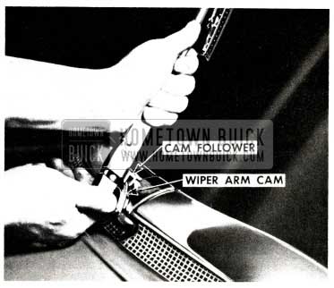
WINDSHIELD WIPER ARM CAM
1955 BUICK MODELS 72, 76R & 76C
A windshield wiper arm cam on the wiper transmission shaft and larger diameter pulleys on the wiper auxiliary drive have been added to provide an increase in the wiping area, thereby improving visibility. The wiper arm cam is secured to the transmission shaft by the transmission spanner nut. A cam follower located on the wiper arm rides over the wiper arm cam. The cam controls the position of the wiper arm, maintaining blade-to glass contact at all times particularly over the sharp backward sweep of the windshield glass.
During February production a change was made to the Windshield Wiper Arm Cam, used on the 1955-70 Series only. This change consisted of adding a second lug on the Cam which fits into a corresponding notch that has also been added to the Windshield Wiper Transmission Escutcheon.
This second lug and notch were added to these parts to prevent the possibility of the Cams being installed improperly, as to Right and Left for production. Since the part numbers were not changed, you may receive Cams for service with either one or two lugs on them. When a Cam with two lugs is received for installation with an escutcheon with only one slot, it will only be necessary to grind off the extra lug. The Escutcheon part numbers were not changed, as they are interchangeable and can he used. lf an Escutcheon is received with only one slot for use with a Cam with two lugs, the second lug can be ground off as above.
The Parts involved are as follows:
Group 10.147 – 4665771 -Cam-Windshield Wiper Arm – Right – 1955-70
Group 10.147 – 4665772 -Cam-Windshield Wiper Arm – Left – 1955-70
Group 10.166 – 4665777 – Escutcheon-Windshield Wiper Transmission – Right – 1955-70
Group 10.166 – 4665778 – Escutcheon-Windshield Wiper Transmission – Left – 1955-70
The windshield wiper arm cam, shown in Figure 97 must be removed in any service operations requiring the removal of the wiper transmission escutcheon.
1955 Buick Windshield Wiper Arm Cam Installation and Removal
The wiper arm cam is removed and installed in the following manner:
REMOVAL AND INSTALLATION
- Remove wiper arm and blade assembly by raising the upper section of the wiper arm to disengage the cam follower from the cam, as shown in Figure 97. With wiper arm in raised position, carefully pull or pry arm from transmission shaft.
- Remove transm1ss10n spanner nut, shown in Figure 98.
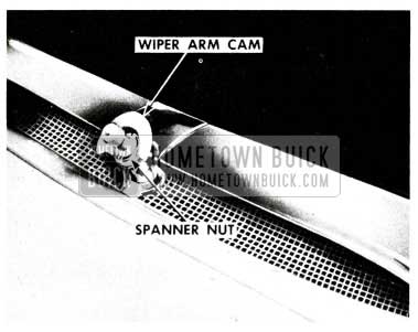
1955 Buick Windshield Wiper Arm Cam
TRANSMISSION CABLE TENSION ADJUSTMENT
Cable tension adjustment is performed in the same manner as on the past model with the “push-in” type transmission shaft. However, with the incorporation of the wiper arm cam the wiper arm must be removed in order to push in the end of the transmission shaft.
EXCESSIVE WIND NOISE
1954 MODELS
A certain amount of wind noise is considered normal in the ventilator area. However, in the event a condition is encountered where the wind noise is excessive and objectionable, the affected area should first be checked for alignment of the ventilator, weatherstrips, door, windshield reveal moldings, etc. If the objectionable wind noise still exists after any necessary adjustments are performed, the following procedure may be used to install new type parts which will improve the wind seal in this area.
The following parts are necessary to perform the rework on 1954 models 46R and 66R.
Gr. #10.722 Part #4657465-6 Mechanical Sealing Strip Outer Weatherstrip Assembly – Rt. & Lt.
Gr. #10.694 Part #4655267-8 Door Hinge Pillar and Bottom Weatherstrip – Rt. & Lt.
Gr. #10.694 Part #4657496 Front Body Hinge Pillar Auxiliary Weatherstrip – Upper
Gr. #10.722 Part #4158056-7 Side Roof Rail Mechanical Sealing Strip Outer Weatherstrip – Frt. Rt. and Lt.
- Remove first type side roof rail mechanical sealing strip outer front weatherstrip assembly by removing two (2) attaching screws located on the side roof rail and at the windshield pillar.
- Apply body caulking compound to seal the screw hole in the windshield pillar. See ”A” in Figure 99.
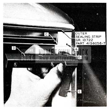
1955 Buick Wind Noise Removal
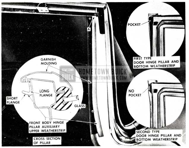
1955 Buick Window Door Hinge Pillar
To correct excessive wind noise on 1954 models 56 R and 76 R the following parts are necessary to perform the rework.
Gr. 10.722 Part No. 4657479-80- Mechanical Sealing Strip Outer Weatherstrip Assembly – Right and Left.
Gr. 10.694 Part No. 4657497 – Front Body Hinge Pillar Auxiliary Weatherstrip – Upper (two required)
- Remove first type side roof rail mechanical sealing strip outer front weatherstrip assembly, by removing the attaching screw located along the side roof rail.
- Apply weatherstrip cement to surface “C” of the new type weatherstrip Gr. 10.722 Part No. 4657479-80) and install weatherstrip to the side roof rail mechanical sealing strip. See Fig.101 NOTE: Exercise care so that the cutout portion of weatherstrip at “A” seats itself around forward portion of mechanical sealing strip at “B” indicated in Figure 101.
1955 Buick Window Door Hinge Pillar Measurement
1955 Buick Window Door Hinge Pillar Weatherstrip
CAM- O- MATIC SPEED CORRECTION
1955-70 Series
We have received a few reports that the two-speed Cam -0-Matic windshield wiper on 70 series cars would only operate on one (1) speed. If this condition in encountered in the field, it is probably caused by the vacuum hose being assembled incorrectly. Correction can be made by following the instructions and diagram in Figure 103.
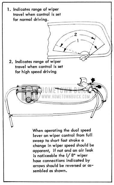
1955 Buick Windshield Wiper Range
REAR DOOR WINDOW WEDGE PLATE CHANGE
1955 Model 43-63
At the start of production on the 1955 Model 43-63 the Rear Door Window Wedge Plates, Group 10.769 used were interchangeable in that there was (1) Male Wedge Plate, Part No. 4666257 and (1) Female Wedge Plate, Part No. 4666315 which were used on both the Right and Left Rear Doors. A change was recently made in production to improve the action of these wedge plates. This change consisted of releasing new Right and Left Male Wedge Plates and Right and Left Female Wedge Plates. In order to furnish the latest type Wedge Plates for Service, only the new type will be available. When using the new Wedge Plates to replace the old, it will be necessary to install them in pairs, that is, a Right Male and Female or a Left Male and Female if either one of the first type needs replacing.
Following are the parts involved:
Group 10.769 – 4666257- Plate-Rear Door Window Wedge – Male
Replace By:
Group 10.769 – 4676871 – Plate-Rear Door Window Wedge – Male-Right
Group 10.769 – 4676872 – Plate-Rear Door Window Wedge – Male-Left
Group 10.769 – 4666315 – Plate-Rear Door Window Wedge – Female
Replace by:
Group 10.769 – 4676873 – Plate-Rear Door Window Wedge – Female-Right
Group 10.769 – 4676874 -Plate-Rear Door Window Wedge – Female-Left
Since these parts are Factory items, this change should be made in your Parts Book at once.
REAR DOOR WINDOW RATTLES
SUGGESTED REPAIR PROCEDURES FOR ELIMINATING RATTLES
IN REAR DOOR WINDOWS
1955 Buick 43 & 63
The following procedure has been prepared to assist in the correction of rattles in the rear door window installation on models 43 and 63. Due to the unusual number of moving parts in this particular door, the correction of any rattle complaint depends primarily upon proper diagnosis to determine the cause of the condition.
GENERAL
These operations should be performed before any of the other repairs outlined in this bulletin:
- Before removing any parts, carefully check for rattles and causes for rattles by both road testing and normal slamming of the doors. Checks should be made with window in up, intermediate and down positions.
- Remove door trim assembly and tighten any loose attaching screws or adjusting studs located on the door hinge pillar, door inner panel or door lock pillar.
- Check remote control connecting rod and locking rod for proper clip retention.
- Re-check for internal rattles which will require adjustment and/or disassembly.
ADJUSTMENTS AND REPAIRS
If rattles still exist after GENERAL operations are performed, the following adjustments and repairs may be made:
- Check and correct door for proper alignment in the body opening.
- Check door window for proper operation and adjustment. If necessary, adjust window as described in Preliminary Door Service Operation Booklet attached to BPS 2.386. Make certain that each part is providing the action for which it was intended.
If the window frame lower front stop on early production bodies cannot be adjusted to provide a positive stop for the window in the down position, replace stop with Window Frame Lower Rear Bumper Stop Assembly Gr. 10.768 #4666415 shown in Fig. 104. This change has been incorporated in recent production.
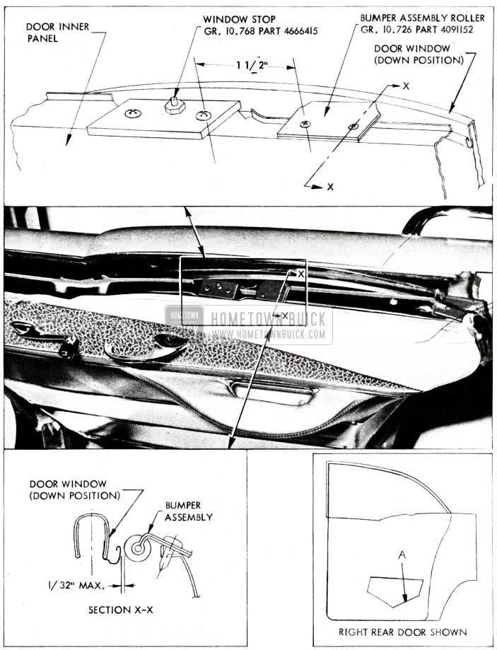
1955 Buick Rear Door Window Assembly
- As indicated at “A” in Figure 104, on early production electrically equipped doors cement a 2 inch square piece of sponge rubber (approximately 3/8 inch thick) to either the door inner panel or the regulator motor to prevent “drumming” of the motor on the inner panel.
- If, on early production bodies, the door does not have a bumper of any type at the top of the door inner panel to eliminate side play of the rear end of the window when window is in down position, install a Gr. 10.726 #4091152 Bumper Assembly (roller) as follows. (See Figure 104 and section X-X):
- Locate and install bumper assembly (roller) 1-1/2 inches rearward of window stop as indicated in Figure 104.
- Adjust bumper so that roller portion is not more than 1/32 inch away from “gutter” on window sash channel frame. (See Section X-X and inset). CAUTION: Roller should not contact ”gutter”.
FOLDING TOP BOOT INSTALLATION
ALL 1954 & 1955 CONVERTIBLE STYLES
In answer to many requests for information pertaining to the service installation of folding top dust boot and fastener, the following is submitted.
The replacement folding top dust boot is serviced without the boot fasteners attached; the fasteners are packaged with the new boot. The boot is serviced in this manner so that a good boot fit may be obtained by locating the position of the fasteners individually with the boot in position on the body.
1954 MODEL
Small Size (for use on pinchweld finishing molding stud fasteners) Socket – Folding Top Dust Boot Fastener Group #13.384 Part #272773
Button – Folding Top Dust Boot Fastener Group #13.384 Part #272771 (Chrome) Part #272772 (Black)
Large Size (for use on folding top compartment side panel stud fasteners) Socket – Folding Top Dust Boot Fastener Group #13.384 Part #105195
Button – Folding Top Dust Boot Fastener Group #13.384 Part #4565454 (Chrome) Part #105502 (Black)
1955 MODEL
The 1955 models use the above described large size fasteners at all locations.
The procedure for installing a replacement folding top dust boot is as follows:
- Lower the top and fold as described in the owner instruction booklet “How to Operate the Folding Top.”
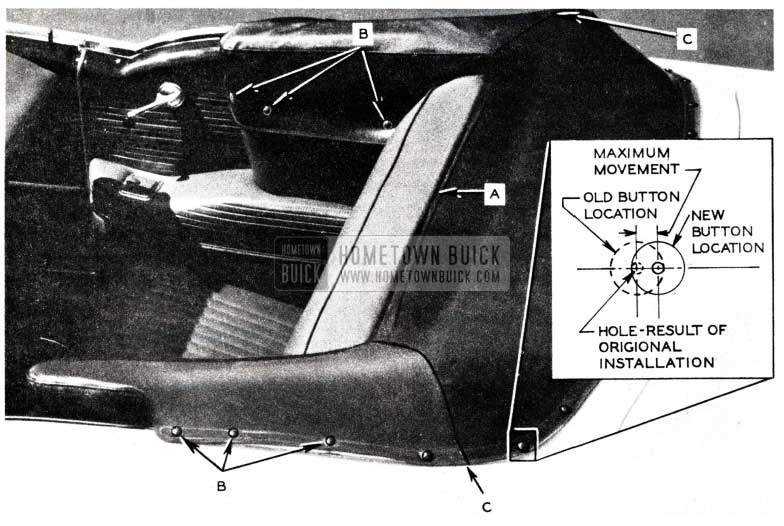
- Slide front edge of folding top dust boot into seat back retainer indicated at “A” in Fig. 105. Make sure that boot is centered in retainer.
1955 Buick Folding Top Boot Installation
1955 Buick Hand Press
1955 Buick Hand Press Socket
PROCEDURE FOR RELOCATING FOLDING TOP DUST BOOT FASTENERS
In some cases, relocating the top boot fasteners will improve the fit of the top boot. The maximum distance a fastener can be moved in any direction is approximately the radius of the button, as shown in inset. If the fastener is moved more than the radius of the button, the hole from the original installation will be exposed. The procedure for determining and marking the correct location of the fasteners is outlined under “Procedure for Installing a Replacement Folding Top Dust Boot.”
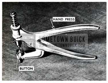
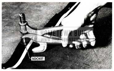
The tools for installing dust boot fasteners are available through the national distribution system of the United-Carr Fastener Company of Cambridge, Massachusetts. This concern maintains a number of Branches throughout the country. The tools and Branch Office locations are listed below. For your information, the approximate price of these tools, available through their Branch office is also listed.
TOOL REQUIREMENTS
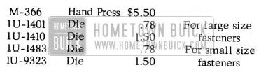
1955 Buick Folding Top Tool Requirements
United-Carr Fastener Company Branch Offices
Atlanta 3, Ga., 133 Luckie Street, N.W. Buffalo 21, N. Y., 463 Huxley Drive
Boston, Mass. (31 Ames Street, Cambridge 42) Chicago 1, Ill., 35 E. Wacker Drive
Cleveland 13, Ohio, 1468 W. Ninth Street
Detroit 11, Michigan, 2832 E . Grand Blvd.
Los Angeles 17, Calif., 1709 W. Eighth Street
New York 10, N. Y ., 15 E. 26th Street
Philadelphia 40, Pa., 3701 N. Broad Street
Syracuse, New York, 31 Wexford Rd., DeWitt
ELECTRIC WINDOW REGULATOR CORRECTION
1954-5 ELECTRICALLY -OPERATED WINDOWS
If an electrically-operated window does not function properly, the condition may be due to an electrical failure in the window control electrical circuit or a mechanical failure in the window regulator assembly. To insure an effective repair of the condition, the following procedure is recommended in the order indicated:
- Check the electrical circuit.
- Remove the regulator assembly from body.
- Remove motor from regulator
- Check regulator.
- Check motor.
- Mount motor to regulator.
- Check window glass installation.
- Install regulator assembly in body.
The procedures and references for performing the above operations are as follows:
CHECKING THE ELECTRICAL CIRCUIT
See the 1954 Fisher Body Service News No. 3, Buick No. 1, page 46-49.
REMOVING THE REGULATOR ASSEMBLY FROM THE BODY
If no defects are found in the electrical system, check the regulator assembly installation to determine whether or not the motor pinion gear is jammed at the end of the regulator sector gear. This information is required for a subsequent operation, “Checking the Regulator”. After the motor pinion gear to regulator sector gear relationship has been established, carefully remove the regulator assembly from the body as described in the 1954 Fisher Body Service News No. 3, Buick No. 1, page 18.
NOTE: The steps below may be used to get a “jammed” window to operate so that it can be positioned for removal of the regulator but in no case should they be considered as repairs.
- Tap the motor housing.
- Tap the inner panel.
- Loosen the regulator backplate mounting screws. It may be necessary to completely remove at least two of these mounting screws before unit will operate.
CHECKING THE REGULATOR
Carefully check the regulator assembly for the following items and make repairs as shown, if necessary. See Figure 108.
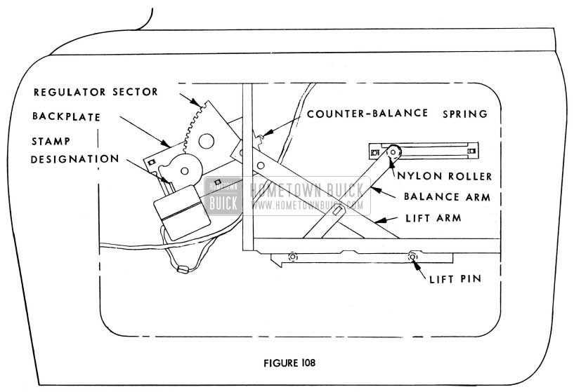
1955 Buick Electric Window Regulator Assembly
- Evidence of Pinion Gear Overtravel on Sector Gear – If the check of the regulator assembly Installation revealed that the motor pinion gear had jammed at the end of the regulator sector gear, extra teeth may be filed at the end of the sector gear. It is extremely important to make the extra teeth conform to the rest of the teeth, otherwise the condition can recur. Carefully check the added teeth for proper fit with the pinion gear teeth.
Note: On the rear quarter window of 1954 Convertibles, the above operation is to be performed only if this one operation will make the regulator standard. If the regulator is found to have additional defects, it should be replaced with Rear Quarter Window Electric Regulator Assembly – Less Motor, Gr. 11.041, Part #4157308 – RT., 4157309 – Lt. This assembly has 76 teeth on the sector gear; the first type had 73 teeth on the sector gear.
- Extreme Side-Play of the Sector Gear – If backplate or side of sector gear next to the backplate show that surfaces are contacting on any portion of the travel of the sector gear, the assembly should be replaced. (Paint will be scraped off at areas of contact). This condition is due to a loose stud at the counter-balance spring and sector gear to backplate.
- Lift Arm Pins Too Loose – If any of the lift pins (the studs which retain the nylon roller to the regulator assembly) are loose, they should be tightened to prevent the pins from falling off and disengaging window from regulator during operation. The pins are of a rivet type construction and can be tightened by a normal riveting procedure. If they cannot be tightened satisfactorily, replace the regulator.
- Nylon Rollers Binding in Channels – If the rollers do not slide easily in their channels, greater clearance may be obtained by filing edge of channel or aligning channel to roller with pliers.
- Bent or Distorted Regulator Backplate – Replace regulator assembly.
- Lubrication:
- If operation is noisy due to lack of lubrication between the coils of the counter-balance spring, lubricate between the coils with a graphite grease.
- Lubricate all studs with a medium grade oil. During the 1954 Model Year, stamped numerical designations were added on the motor gear housing web to identify the construction of the unit. Motor types used to date, which may be found in the field, include the following stamped designations:
NOTE: Stamp designations were assigned in advance of motor releases; they do not indicate the actual sequence of release. See Figure 109.
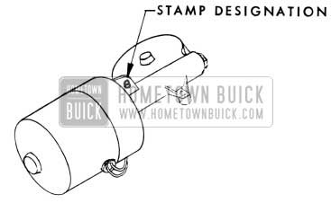
1955 Buick Stamp Designation
- No Stamp – Fast motor with narrow nylon gear.
- Stamp #4 – Slower motor with reinforced narrow nylon gear.
- Stamp #5 – Slower motor with wide nylon gear, third bearing and molybdenum type lubrication.
- Stamp #7 – Slower motor with reinforced narrow nylon gear and third bearing.
- Stamp #8 – Slower motor with wide nylon gear, third bearing and paste type grease lubrication.
- Use of Service Package in Field – New service packages have also been released to modify certain motor types in the field by replacing the nylon gear and pinion assembly with a gear and rubber coupling assembly. The service packages include a gear and rubber coupling assembly, lubricant, cover and instructions.
The service packages should be used to modify the following motors:
- Number 5, 7, and 8 motors which have jammed due to the nylon gear binding on the worm gear.
- Number 5, 7, and 8 motors in service stock. Modification must be made at time service replacement motor is put into use.
- Number 5 motors which operate very slowly in cold weather.
The new service packages have been released as follows:
- Door and Rear Quarter Window Electric Motor Service Package, Gr. 10.783, Part No. 5097959. (For use on door windows and on rear quarter windows of Special Coupes).
- Rear Quarter Window Electric Motor Service Package, Gr. 11.041, Part #5097960. (For use on rear quarter windows of Convertibles only).
The procedure for installing a new gear and rubber coupling assembly is as follows:
- Pierce the gear and pinion assembly cover with a sharp tool and pry cover loose from the housing.
- Lift out the gear and pinion assembly.
- With the motor assembly in an upright position and the gear housing positioned below the motor, wash out gear housing and worm gear with a suitable solvent such as mineral spirits. Use a small brush to clean around the worm gear.
- Re-lubricate gear housing, worm gear and nylon teeth of new gear and rubber coupling assembly with grease type lubricant furnished in service package. Also lubricate the gear assembly shaft that fits into the die cast housing.
- Place the new gear and coupling assembly in the gear housing.
- Carefully press the new cover into place.
- Check operation of motor in both directions before installing to regulator.
MOUNTING THE MOTOR TO THE REGULATOR BACKPLATE
See the 1954 Fisher Body Service News No. 3, Buick No. 1, page 18.
NOTE:
- Be sure the three motor mounting studs properly “bottom” in the regulator backplate holes.
- Oil the pinion shaft which fits into the backplate bearing with a medium grade of oil.
CHECKING THE WINDOW GLASS INSTALLATION
- Check for misalignment of glass with glass run channels. See Fisher Body Service News No. 3, Buick No. 1, page 5 for adjustments.
- Lubricate bearing surfaces of cam flanges for nylon rollers with lubriplate.
- On four-door sedan styles, check the door window lower stop bumper. If the bumper is approximately 1 3/16 inches square and 1/4 inch thick, it should be replaced with a new, larger Door Window Stop Bumper Gr. 10.716 Part No. 4609684. This bumper is approximately 1 5/16 inches square and 1/2 inch thick. The door window stop bumper is accessible through the nearest access hole in the door inner panel. On rear doors, check the operation of the window after the thicker bumper has been installed. If the window glass will not lower to a position flush with the door window lower reveal molding due to the glass “Bouncing• up on the thicker (1/2 inch) bumper, replace the thicker bumper with the original 1/4 inch thick bumper.
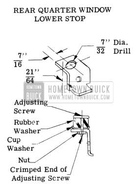
- On the rear quarter window of 1954 Special Coupes (not convertibles), check the rear quarter window stops. If the stops do not have rubber bumper assemblies, install Rear Quarter Window Electric Motor and Regulator Stop Bumper Package Group 11.041 Part #4241691 as follows:
- Remove rear quarter window upper stop and replace it with the new type upper stop assembly (includes bumber assembly) found in the service package.
NOTE: The upper stop should be installed with the bumper assembly pointing down, thus supplying a cushion for the “up” travel of the regulator arm.
- Remove the rear quarter window lower stop, remove rubber coating, and rework as follows:
- Drill a 7/32 inch hole at location shown in Figure 110.
1955 Buick Rear Quarter Window Lower Stop
NOTE: Do not tighten the attaching nut excessively. Placing the rubber washer into excessive compression will reduce the cushioning effect of the bumper assembly.
INSTALLING REGULATOR IN BODY
See the 1954 Fisher Body Service News No. 3, Buick No. 1, page 16.
NOTE: Carefully check the following points as regulator is being installed in body.
- Check for proper engagement of motor terminals to body wiring harness terminals.
- Check to see that all mounting screws are tight.
- Thoroughly check operation of window before trim is replaced.
- During reassembly of trim, be sure component parts of switch are completely engaged.
POWER WINDOW OPERATION WITH IGNITION OFF
Several requests have been received on how to change the window regulator wiring so that power windows could be operated without having the ignition switch turned on. Engineering advises that dealers should strongly discourage this practice for the following reasons:
- SAFETY Children left in the car can play with the controls and may cause serious injury to any part of the body caught above the glass. In a recent case (not in G.M.) a child left in a car was choked to death when caught across the neck.
- THEFT A window can be easily lowered by pushing any control down with a stiff wire.
It is recommended that owners desiring to have their windows operative with the ignition off should be cautioned on the two hazards mentioned above, if they still want the job done, a signed order may offer protection against any legal action.
The job may then be accomplished by locating the power window relay under the left cowl trim pad, then connect the light blue and the red wires together; this simply connects across the relay, leaving it out of the circuit. See wiring diagram, Figure 10-105 & 106 in the 1954 Shop Manual. With this arrangement the circuit is still protected by the main circuit breaker.
DO NOT attempt to accomplish this job by moving the yellow relay wire from the cold to the hot side of the ignition switch as this will cause a small current drain through the relay at all times.
INSTALLATION OF NEW TYPE WINDSHIELD REVEAL MOLDING
1954-5 Buick “40” and “60” Series
If the Windshield reveal moldings on the above styles must be replaced, it is necessary to use the new type “telescoping” moldings which have been incorporated in production and which have also been released as service parts.
NOTE: Attaching parts for reveal moldings used on 1954 styles and on early 1955 styles are still available for service; however, the reveal moldings themselves have been superseded by the new type “telescoping” moldings.
The new type moldings have the same outward appearance as the original moldings; however, the method of attachment has been revised. The procedure for installing new type windshield reveal moldings on 1954 styles and on early 1955 styles is as follows:
Before installing telescoping type windshield reveal moldings described herein, review the 1954 and 1955 Fisher Body Service News for windshield removal, installation and sealing operations and attachment provisions of original type moldings.
WINDSHIELD UPPER REVEAL MOLDING
- Original Type
The original type upper reveal molding is held in position at the outer ends by the upper end of each side reveal molding.
- Telescoping Type
- Sedans and Special Coupes
The telescoping type upper reveal molding is attached at each end by a clip which is fastened to the roof panel with a .screw. See Figure 111.
- Sedans and Special Coupes
1955 Buick Windshield Upper Reveal Molding
The telescoping type upper reveal molding is attached at each end by an integral retainer which is fastened to the windshield outer upper frame with a screw.
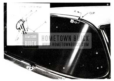
WINDSHIELD SIDE REVEAL MOLDINGS
- Original Type
The original type side reveal moldings are attached at the upper end to the windshield opening pinchweld flange with a bolt and clip assembly. Each molding is attached to the front body hinge pillar with screws. The lower end of each molding is attached with a retainer which is fastened to the upper shroud panel with either a bolt or a screw.
- Telescoping Type
The telescoping type side reveal moldings are “telescoped” over the outer ends of the upper reveal molding. Each molding is attached to the front body hinge pillar with screws. The lower end of each molding is attached with a new type retainer which is fastened to the upper shroud panel with a screw. See Figure 112.
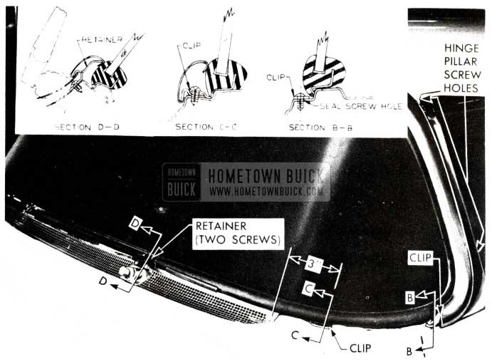
1955 Buick Windshield Retainer Screws
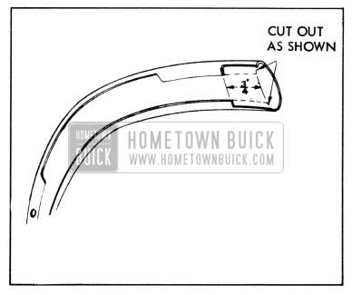
- Replacing an Original Type Side Reveal Molding with a Telescoping Type Side Reveal Molding When Upper Reveal Molding is Original Type
- Remove original side reveal molding and lower reveal molding on affected side.
- Seal original side reveal molding screw holes in front body hinge pillar. Seal windshield outer frame and front body hinge pillar as described in 1955 Fisher Body Service News.
- On all but convertible styles, rework upper end of telescoping type side reveal molding by cutting away flanges as shown in Figure 113.
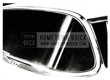
1955 Buick Windshield Upper Reveal Molding – Convertibles
WINDSHIELD LOWER REVEAL MOLDING
- Original Type
The original type lower reveal moldings are attached to the rubber channel by an “L” flange on the moldings. The outer end of each molding is attached with a bolt and clip assembly.
- Telescoping Type
The telescoping type lower reveal moldings are held in position at the outer ends by the side reveal moldings. Each lower reveal molding is also attached with a retainer located outboard from the shroud top ventilator screen, a retainer at the windshield wiper transmission and the center retainer.
- Replacing an Original Type Lower Reveal Molding With a Telescoping Type Lower Reveal Molding on Body Having Either Original or Telescoping Type Side Reveal Molding
NOTE: The changes listed in this procedure were incorporated during 1954 style production; therefore, some bodies will not require all of the rework operations.
- Remove original windshield lower reveal molding. See 1954 Fisher Body Service News.
- Seal original lower reveal molding bolt hole in body with caulking compound.
- Drill a 1/8 inch diameter hole in upper shroud panel at a location 3 inches outboard from outboard screen-to-shroud screw. Apply medium-bodied sealer to hole and install lower reveal molding clip. See Fig. 112, Section C-C.
- Locate windshield lower reveal molding retainer above windshield wiper transmission. Drill 1/8 inch diameter holes in upper shroud panel for retainer and install retainer -to-shroud panel screws. See Fig. 112, Section D-D.
- Install latest type lower reveal molding. See Figure 114.
1955 Buick Windshield
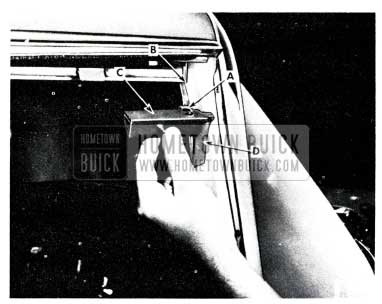
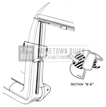
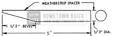
SIDE ROOF RAIL WEATHERSTRIP SPACER INSTALLATION
1955 Buick 43-63 Models
If a water leak is encountered between the side roof rail weatherstrip and the front door ventilator frame which cannot be corrected by adjustment of parts, a side roof rail weatherstrip spacer may be required. This spacer provides additional support for the intermediate lip of the weatherstrip and will improve the water seal in this area. The procedure for performing this operation is as follows:
- Obtain a 5-inch length- of round rubber weatherstrip of 1/2 inch diameter. Note. Purchase locally.
- Bevel the weatherstrip for a distance of 1-1/2 inches at one (1) end, as shown in Fig. 115.
1955 Buick Side Roof Rail Weatherstrip Spacer Installation
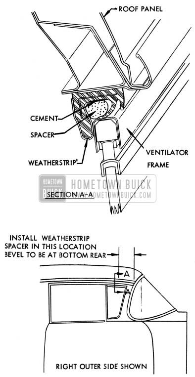
1955 Buick Install Weatherstrip Spacer
Insert the spacer behind the intermediate lip of the weatherstrip and as far forward as possible, with the beveled edge toward the bottom rear. See. Figure 116.
NOTE: Keep cement on indicated surfaces only. Carelessly applied cement on the sealing lips of the weatherstrip may decrease the effectiveness of the repair.
LUBRICATION OF SIDE ROOF RAIL WEATHERSTRIP
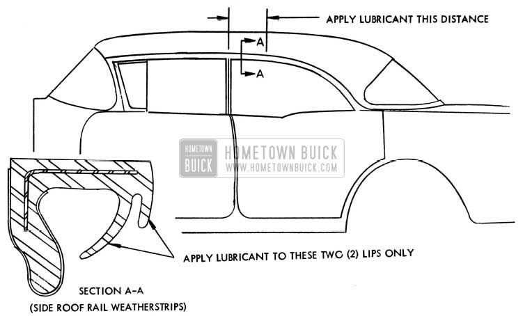
1955 Buick “43” and ”63” Series
The new Special Sedans (43 and 63 model) are equipped with one-piece side roof rail weatherstrips which extend from the front body hinge pillar to the rear body lock pillar. During normal maintenance on these bodies, periodic applications of a silicone rubber lubricant to the weatherstrip will serve to prevent squeaks and scuffing caused by the contact of the chrome window channels and the rubber sealing lips of the weatherstrip.
NOTE: Some early production bodies are equipped with weatherstrips which are entirely cloth-covered. These weatherstrips do not require lubrication. If excessive scuffing occurs, causing damage to the cloth-covered sealing lip, the entire weatherstrip should be replaced with a new weatherstrip which is only partially cloth-covered and which is identified as follows:
Weatherstrip Assembly, Side Roof Rail Gr. 10.722 – 4665018 Rt. – 9 Left
One area on the rubber side roof rail weatherstrip requires special attention. This area is the section immediately over the center body pillar, at the point of contact with the rear door chrome glass channel front corner where special lubrication is required during the first 5,000 miles. As shown in Figure 117 a silicone rubber lubricant should be applied to the outer sealing lips of the weatherstrip at the new car inspection and every 1,000 miles for the first 5,000 miles. These five (5) applications, together with applications during normal maintenance, will provide a sliding surface for the glass channel and will prevent excessive scuffing.
1955 Buick Weatherstrip Assembly Lubrication
REWORKING AND ADJUSTING REAR DOOR LOCK REMOTE CONTROL ASSEMBLIES
1955 Buick 43 – 63
This information supercedes (Re-locating Rear Door Lock remote control assembly) covered in B.P.S. 2.387, dated April 22, 1955.
If a rear door on the above styles cannot be opened with the inside remote control handle, when the inside locking control handle is in the unlocked position, the condition may be caused by insufficient travel of the remote control connecting link and/or improper positioning of the remote control assembly.
The procedure which follows outlines the method for reworking and adjusting the remote control assembly to obtain proper operation.
- Remove door inside hardware, door trim panel assembly and door inner panel access hole cover.
- With door lock in unlocked position and freewheeling, detach remote control connecting link and remove remote control assembly. (See the 1955 Four-Door Special Sedan Fisher Body Service News for the “Free- Wheeling” adjustment procedure.)
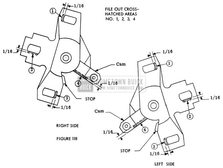
- Rework remote control assembly as follows:
- File out the three slots 1/16 inch in the remote control assembly as shown by the dotted lines in Fig. 118 (right rear door) and Fig. 119 (left rear door) to provide for additional rotational adjustment of the remote control assembly on the door inner panel.
1955 Buick Remote Control Assembly
- File out the cam 1/16 inch as shown by the dotted lines in Fig. 118 (right rear door) and Fig. 119 (left rear door) to obtain additional travel of the remote control connecting link.
- Install the remote control assembly to the door inner panel as far rearward as possible and engage the connecting link. If the door will not open with the remote control assembly in this position, move the remote control assembly forward slightly until the remote control assembly is properly positioned to release the lock which in turn will allow the door to open.
NOTE: In addition to moving the remote control assembly forward it may be necessary to rotate the remote control assembly slightly. The required remote control assembly adjustment may be a combination lateral and rotational adjustment. It is important that this adjustment be carefully made. - Check all phases of the lock operation several times and install previously removed parts.
It is recommended that where a lock is changed from conventional to free-wheeling that the lock be thoroughly checked for proper operation.
DOOR LOCK CAMPAIGN
1955 Model 43 and 63
Following is a reprint of Special (Red Band) Service Letter, Dealer No. 159 dated May 6, 1955, covering the Extension of the Door Lock Campaign on 1955 models 43 and 63.
This is notification to the effect that “Door Lock Campaign” described in Special Service Letter (Red Band) No. 155, dated March 31, 1955, has been extended to include all models 43 and 63 built from the beginning of production through approximately April 29, 1″955. Models 43 and 63 having serial numbers lower than those listed below, by assembly plants, must be campaigned as outlined in the above mentioned letter.
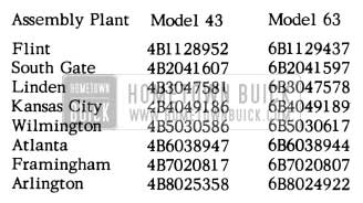
1955 Buick Door Lock Campaign Cars
Group and Part numbers of door locks remain unchanged; however, all replacement front door locks should have a number “3-1-1” or higher stamped on them, and rear door locks should have a number “3 -14-1” or higher. The numbers indicate month, day and shift on which the locks were manufactured. All locks having numbers lower than those mentioned above should not be installed. They should, however, be returned to the dealer’s normal shipping warehouse on or before June 15, 1955, for credit.
Both 1st and 2nd type locks are identical in appearance when installed on doors; therefore, body numbers must be used to identify those models which must be inspected.
Group and part numbers of the latest type locks which are available from all parts warehouses are listed below:
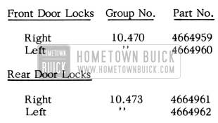
1955 Buick Door Lock Campaign Parts
The Parts Department did not stock the type of lock which is suspected of being defective; therefore, all locks shipped from the Parts Department will be of the latest production type.
Procedure for Checking Front and Rear Door Lock Safety Catch
Models 43 and 63
The procedure which follows should be performed exactly as explained to check the action on the front and rear door lock safety catch.
NOTE: Although illustrations are of a front door, this procedure should be performed on all four (4) doors.
- Move door from “open” position to “Safety”” position as indicated in Figure 120, steps 1 and 2 Lock will “click” once to indicate safety position.
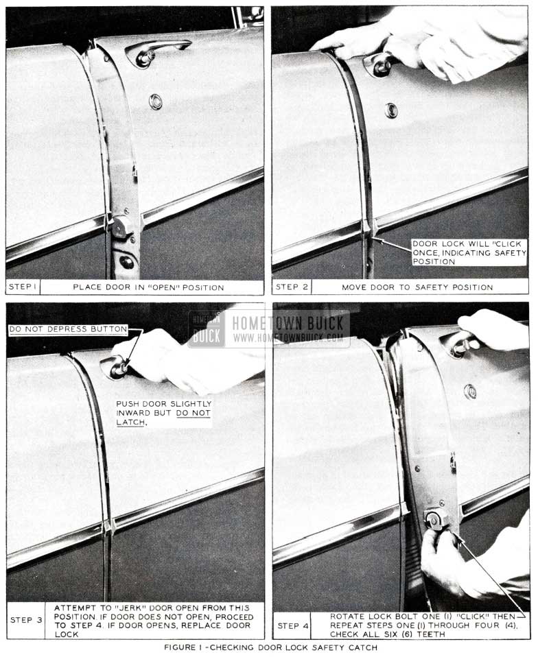
1955 Buick Door Lock Adjustment
Flat Rate Operation for this campaign is as follows:
- Check operation of all four (4) doorlocks-.2hr.
- Door Lock (one) – R&R – Front Right 1.1 hr – Left 1.1 hr. – Rear Right 1.0 hr – Left 1.0 hr
NOTE: The above flat rate operation for door lock replacements does not include the
.2 hrs. allotted for checking; therefore, .2 hr. must be added to this operation.
Submit one (1) AF A per car, using time allowance mentioned above. Do not include more than one car per AF A and, of course, all parts replaced must accompany AF A. Dealers will receive credit at regular campaign rates.
DOOR LOCK STRIKER CAMPAIGN
Following is a reprint of Special (Red Band) Service Letter Dealer No. 156 dated April13, 1955, covering the ”Door Lock Striker Plate Campaign”.
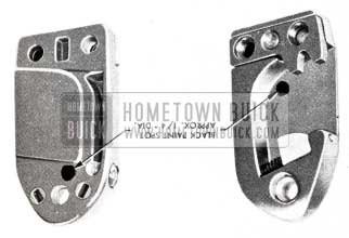
Effective immediately, door lock striker plates on 1955 models 43 and 63 produced from beginning of production through approximately April 6th are to be campaigned 100 per cent. Every door lock striker plate on these models must be replaced by a special heat-treated striker plate which can be easily identified by a black “daub” of paint (approximately 1/4″ in diameter) as indicated in Figure 121.
1955 Buick Door Lock Striker
Body and serial numbers of Models 43 and 63 which were the first to be equipped with the heat treated type striker plate are listed below by assembly plants.
All models 43 and 63 having numbers lower than those listed below must be campaigned for the new striker plate installation.
In addition to models 43 and 63 listed for the Arlington Assembly Plant, the following body numbers will identify other 40 and 60 series models which must also be campaigned.
1955 Buick Arlington Assembly Plant
Should other assembly plants report the need of campaigning additional series 40 and 60 models, serial numbers will be sent directly to those zones affected.
Since the only change involved in the door lock striker plate is the added heat-treatment process, group and part numbers have not been changed. The Parts Department, however, has frozen old type striker plate stock and only the new heat treated type (shown in Figure 121 ) is now available at all parts warehouses.
The following are group and part numbers for door lock striker plates which are applicable to all Series 40 and 60 models.
1955 Buick Door Lock Striker Plate Parts
Flat Rate operation for this campaign is as follows:
Door lock striker plate (one) R&R – .1 hr. (for each additional, add .1 hr.)
Since a campaign for checking door lock operation is now in progress for models 43 and 63 as described in Special Service Letter (Red Band) Dealer No. 155, it is suggested that both campaign operations (described in letter 155 and 156) be performed on these models at the same time, and the work of both submitted on one ( 1) AFA. Do not include more than one car per AF A, and return replaced parts properly tagged with AFA through normal channels. Dealers will receive credit at campaign rates.
1955 Buick Door Lock Striker Flat Rate Operation
DOOR LOCK & STRIKER
1955-50 and 70 Series
Supplementing the article ”Door Lock and Striker” in B.P.S. #2 .386 dated April 8, 1955, the following procedure is recommended for application of emergency lock striker spacers, used on 1955-50 and 70 Series cars.
- Check door for proper alignment and correct any door fit conditions caused by either improper hinge adjustments and/or body shimming figure122 illustrates the new lock & striker.
1955 Buick Door Lock and Striker
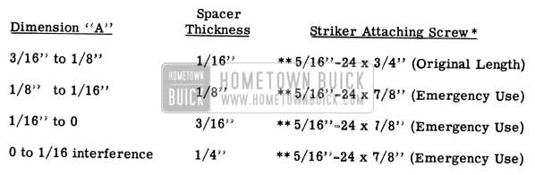
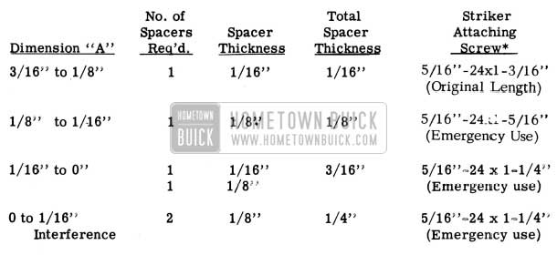
When dimension “A” (see Fig.123) from the inside face of the striker teeth to the center of the extension metal thickness is less than 3/16 inch, install emergency spacers and proper length striker attaching screws as specified below:
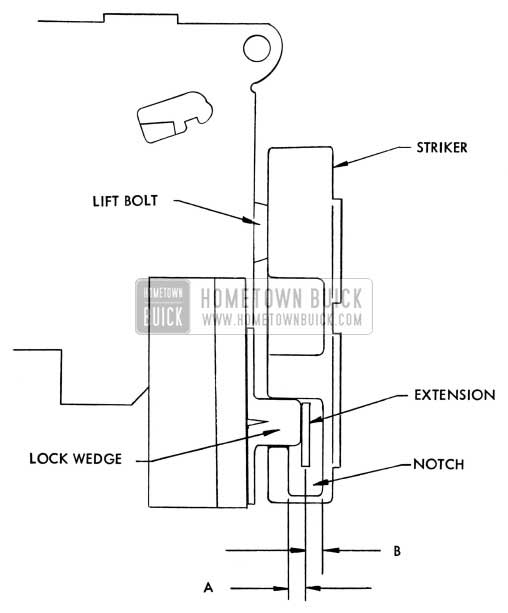
1955 Buick Door Lock and Striker – Roadmaster Series
1955 Buick Door Lock and Striker Legend
NOTE: Dimension “B” in Fig. 123 from center of the extension metal thickness should never be less than 1/8 inch.
Asterisk (*) indicates zinc or cadmium plated flat head cross recess screw with countersunk washer.
NEW DOOR LOCK & STRIKER
Inter-Lock Feature
1955 Buick 40 and 60 Series
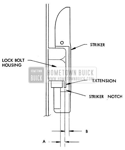
In the near future, new door lock and striker assemblies with an inter-lock feature to provide fore and aft locking will be incorporated in production. The door lock has an extension which engages a mating notch in the striker when the door is closed. The production tryouts have been completed; therefore, some bodies with the new door lock and striker assemblies are already in the field. Figure 124 illustrates the new door lock and striker assemblies.
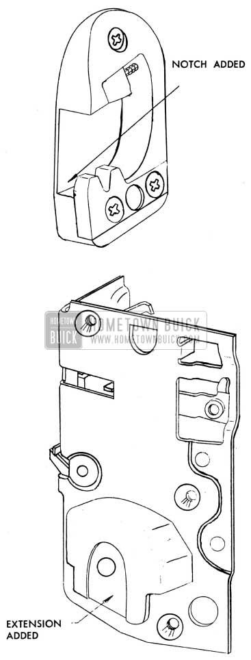
1955 Buick Door Lock and Striker – Special and Century Series
The new door lock and striker assemblies are removed and installed in the same manner as the present door lock and striker assemblies, however, two (2) different thicknesses of striker spacers and an emergency striker attaching screw have been released to provide for proper lock bolt engagement in the striker. Dimensional specifications for determining emergency spacer requirements are also listed.
The new door lock striker assemblies with the interlocking feature are interchangeable with the original type striker assemblies. The new type door lock strikers were ‘available for production before the new type door locks with the interlocking feature. Therefore, the assembly plants are installing the new type strikers on bodies with the original type locks.
When checking the lock bolt engagement on bodies equipped with the new interlocking type striker plates and original type door locks, see the Fisher Body Service News for instructions.
DIMENSIONAL SPECIFICATIONS FOR USE OF OOOR LOCK STRIKER EMERGENCY SPACERS
- Check door for proper alignment and correct any door fit conditions caused by either improper hinge adjustments and/or body shimming.
- To determine usage of door lock striker emergency spacers, apply modelling clay or caulking compound in the rear of the door lock striker notch where the lock extension engages; then, close the door to form a measurable impression in the clay or caulking compound.
When dimension “A” (See Fig.l25) from the inside face of the striker teeth to the center of the extension metal thickness is less than 3/16 inch, install emergency spacers and proper length striker attaching screws as specified below:
1955 Buick Door Lock and Striker Parts
1955 Buick Door Lock and Striker Parts Legend
NOTE: Dimension (B) in Fig. 125 from center of the extension metal thickness should never be less then 1/8 inch.
Asterisk (*) indicates Zinc or Cadmium plated flat head cross recess screw with countersunk washer.
REPAIRING REAR DOOR LOCKS
1955 BUICK “40” & “60” SERIES -ALL FOURDOOR STYLES EXCEPT FOUR -DOOR HARDTOPS
If a rear door with the lock set in free-wheeling cannot be opened with the inside remote control handle when the inside locking knob is in the up (unlocked) position, the condition may be caused by an improperly installed remote control assembly or a free-wheeling rod that is too long.
The following procedure may be used to check and repair a rear door lock having the above condition:
- Check for correct fore and aft positioning of remote control assembly on door inner panel. If necessary, reposition remote control assembly for proper lock operation by loosening screws and moving remote control to obtain the proper adjustment. NOTE: This may be all that is required to correct condition.
- If lock is still inoperative, remove lock from door.
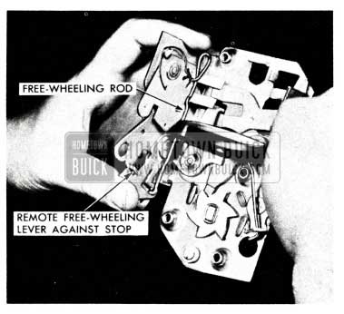
- With trip lever in the up (unlocked) position and free-wheeling rod in free-wheeling position, actuate both remote free-wheeling lever and remote lever against stop on lock frame, as shown in Figure 126.
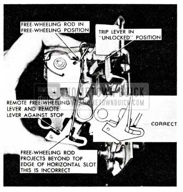
1955 Buick Rear Door Lock Repair
- Place trip lever in down (locked) position. In this position, the lower end of free-wheeling rod is free to travel in horizontal slot of remote free-wheeling lever. (See Figure 127).
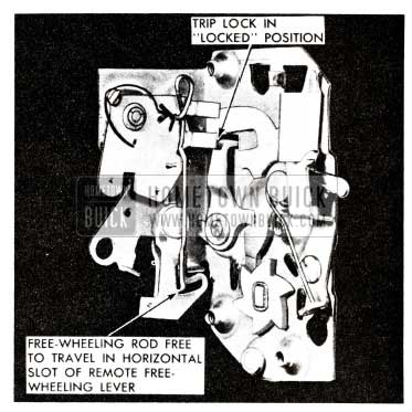
1955 Buick Repair Rear Door Lock
1955 Buick Rear Door Lock Free Wheeling Rod
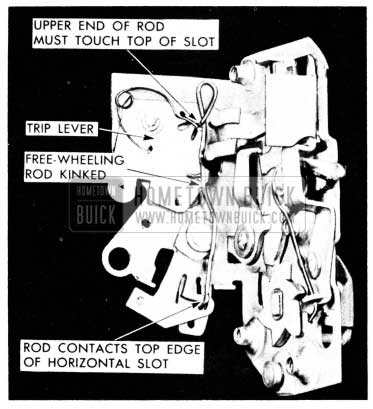
1955 Buick Rear Door Lock Trip Lever
CAUTION: Do not over-kink rod.
to the guide, by decreasing the off-set. When this was done, an adjusting stud was used to attach the guide to the Quarter Inner Panel instead of the screw used in 1954.
In order to furnish the latest type parts for service and decrease service parts inventory, the Parts Department will replace the 1954 Rear Guides by the 19S5 parts when present stocks are exhausted. However, when installing a 1955 Guide in a 1954 car, it will be necessary to use the 1955 adjusting stud for the rear attachment.
Following are the parts involved:
Group 11.040 – 4637060 – Guide-Rear Quarter Window Rear – Right
Group 11.040 – 4637061 – Guide-Rear Quarter Window Rear – Left 1954 46R-66R
To be replaced by:
Group 11.040 – 4659984 – Guide-Rear Quarter Window Rear- Right
Group 11.040 – 4659985 – Guide-Rear Quarter Window Rear –Left 1955 46R-66R
NOTE: When installing 4659984-4659985 on 1954 cars, it will be necessary to order and install Group 11.040-4658800 Stud-Rear Quarter Window Rear Guide (Lower).
DUST LEAKS
1954 – 55 Models
Supplementing the dust leak correction information given in BPS 2 .372, July 30, 1954. There are some additional areas where dust may enter the trunk, which was not covered in that BPS bulletin.
On some 1955, 40 and 60 series bodies the sealing strip had not been pressed into position to obtain a good bond at the joint of the rear quarter side, outer and inner panels, and in other cases the inner panel had not been assembled properly and left a gap between the outer and inner pane I at the rear compartment weatherstrip gutter. See View A & B in Figure 130.
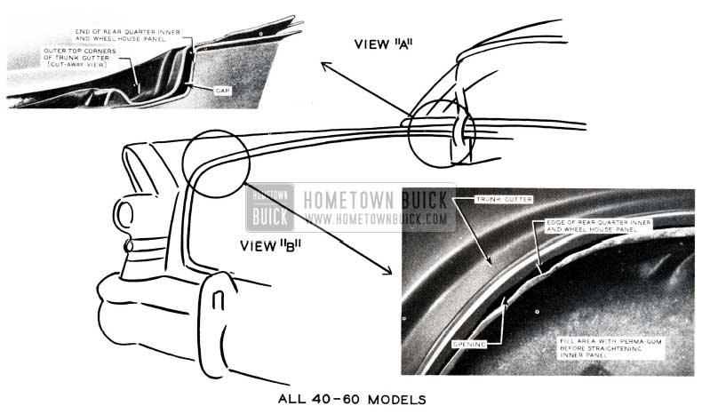
1955 Buick Trunk Cutter
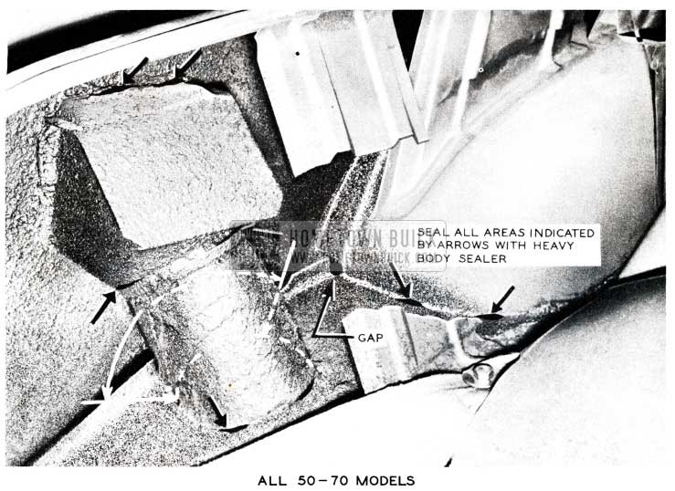
On the 50 and 70 series, dust leaks may occur along the joints of the rear compartment pan rear extension to rear quarter outer panel and around the box and tube section of the gas tank filler neck housing and at the floor pan and wheelhouse junction as shown in Figure 131 & 132. lt is rather difficult to seal some of these areas because they are not visible and are hard to reach.
1955 Buick Body Sealer
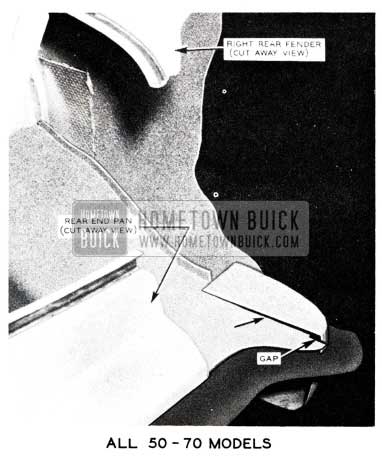
1955 Buick Right Rear Fender
Before attempting any sealing operations remove trim pads and make a general inspection of the rear compartment interior for dust patterns. All sources of dust leaks should be marked with white chalk as they are located. If, after making the inspection, the source of dust leak is questionable, the following additional check can be made.
With a helper on the outside passing a controlled jet of air over the affected area, search the inside of the body with a bright light for evidence of dust source. NOTE: All persons in the area where air is being blown should wear safety glasses.
To properly seal all jobs it is suggested to use either a heavy body sealer or purma -gum sealer, depending on where leak occurs. To seal opening shown in View A, Figure 130, it is easier to use purma-gum because area is only accessible between the hinge box and inner panel. Fill opening shown in View B with purma-gum before straightening inner panel. To seal any opening in 50 and 70 series it is best to brush in heavy body sealer especially in area of the rear quarter outer pan and rear extension See Figure 132.
After all sealing operations have been performed, again check the affected areas with a light. After it has been determined that the required sealing has been done, install the trim previously removed.
Leave A Comment
You must be logged in to post a comment.