1950 BUICK DOOR OUTSIDE HANDLE
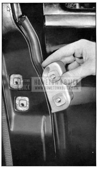
REMOVAL
- Release the 1950 Buick door rubber weatherstrip at the lock pillar face to expose flat spring handle retainer.
- Remove screw holding retainer to pillar face.
- Pull retainer out until handle can be removed.
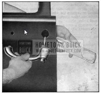
1950 Buick Door Outside Handle Removal
INSTALLATION
- Door lock bolt by pushing to “up” position.
- With push button depressed , install handle. When in correct position, bolt will snap down.
- Install retainer to position.
- Install retainer screw.
- Recement door weatherstrip, using “3M Synthetic Rubber Adhesive.
1950 BUICK DOOR OUTSIDE SAFETY LOCK
- Remove 1950 Buick door outside handle.
- Remove retaining snap ring .
- Remove stop washer, spring, and detent washer, noting relative position of the two washers.
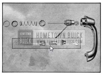
1950 Buick Exploded View – Door Outside Handle
- Remove 1950 Buick door lock cylinder, lock cylinder housing, and push button shaft assembly. This unit slips out of the door handle casting.
- Remove handle sealing ring.
- Remove push button cap by bending up small ears of cap to disengage from lock cylinder housing.
- Remove retainer holding lock cylinder housing and push button shaft to housing. A new retainer will be required at reassembly.
- Remove door lock cylinder and push button shaft from housing.
- To reassemble, reverse this procedure .
FRONT DOOR ARM REST
Note: Although rear 1950 Buick door arm rests are not provided on the “44” Series 4 door dynamic coupe, provisions for the installation of arm rests have been incorporated on all rear door inner panels of this style.
- From the underside of the arm rest, remove the two long screws which hold this assembly to the door inner panel and remove arm rest.
- To install, reverse this procedure.
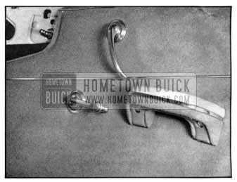
1950 Buick Door Inside Handles and Door Arm Rest
1950 BUICK DOOR INSIDE HANDLES
- Depress the trim pad or door belt finishing molding and insert special pliers or suitable tool behind the escutcheon plate to grip handle retaining spring.
- Carefully remove the retaining spring, then remove handle.
- To install, first insert the handle retaining spring in the handle, then install the handle on the splined shaft of the regulator. Note: Before installation note the angle of the handle on opposite door with window in a closed position.
1950 BUICK DOOR TRIM PAD
- Remove 1950 Buick door inside handles (see Inside 1950 Buick Door Handle Removal).
- Remove the door belt finishing molding (See Door and Rear Quarter Belt Finishing Molding).
- Remove door arm rest (see Door Arm Rest Removal).
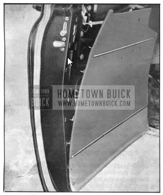
1950 Buick Door Trim Pad Removal
- Remove screws at lower corners of trim pad.
- With a suitable flat tool, pry loose the trim pad at both sides, then raise it from the retaining hooks at center of door and the retainer channel at the bottom.
- To install, reverse this procedure.
FRONT DOOR VENTILATOR REGULATOR
- Remove the 1950 Buick door trim pad (see 1950 Buick Door Trim Pad Removal).
- Remove smaller loading hole cover below the ventilator regulator. This cover is cemented to the inner panel.
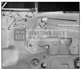
- Disconnect ventilator lower pivot shaft from regulator mechanism by removing hex-head bolt at “A.” See Figure No. 17.
- Remove the four (4) screws indicated at “B” holding regulator mechanism to door inner panel.
- Remove mechanism through loading hole at lower part of door as illustrated.
- To install, reverse this procedure.
1950 Buick Door Ventilator Regulator
ADJUSTMENT
The cap screw “A” may be tightened to take up any excess play the ventilator lower pivot may have through use, while the set screw “C” controls the friction clamp or brake on the regulator mechanism. By tightening or loosening this screw, the ventilator operating handle may be made to operate freely or tightened up, whatever the case may be.
1950 BUICK DOOR VENTILATOR DIVISION CHANNEL
- Remove 1950 Buick door trim pad.
- Release the retaining clips of the glass run channel at the door header only (see Door Glass Run Channel Removal).
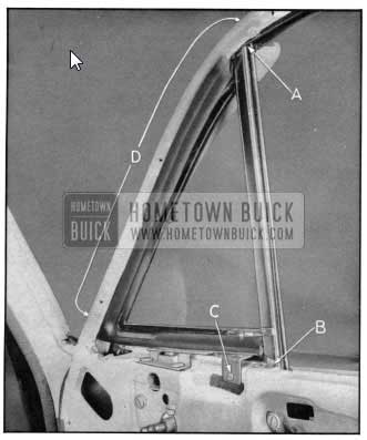
- Remove the single crosshead screw located inside of division channel as shown at “A,” Figure No. 18.
- Remove the screws holding the bracket of the division channel to the edge of the door inner panel at window opening as shown at “B,” Figure No. 18.
- Remove nut and adjusting screw at bottom of channel as shown at “D, ‘ Figure No. 17, noting before removal the length of the screw projecting out through the hole.
- With the door ventilator open, swing division channel out of position, pull up, and remove through the window opening of the door.
- To install, reverse this procedure. Apply “3M Weatherstrip Cement” at top and bottom ends of door ventilator weatherstrip and on contacting surfaces of the division channel at these points.
ADJUSTMENT
To adjust lower end of channel forward or backward, loosen nut shown at “D,” Figure No. 17, and move stud in slotted hole in inner panel the desired amount. To move lower end of channel in or out, adjust the internal stud nut on the opposite side of inner panel, accessible through the loading hole.
1950 Buick Front Door Window Ventilator
FRONT DOOR VENTILATOR
- Remove ventilator regulator mechanism (see Front Door Ventilator Regulator).
- Remove the door ventilator division channel (see 1950 Buick Door Ventilator Division Channel).
- Remove the screw at “C,” Figure No. 18, attaching lower ventilator bracket to top edge of door inner panel at window opening.
- Remove screws at “D, ‘ Figure No. 18, holding ventilator frame to window opening along door header.
- Remove ventilator assembly.
- To install, reverse this procedure. Apply “3M Autobody Sealer” between the contacting surfaces of the ventilator lower attaching brackets and the door inner panel, prior to installing. Also apply a bead of “3M Weatherstrip Cement” on lip of ventilator weatherstrip at the ventilator upper pivot so as to bridge the cutout in retainer at this area.
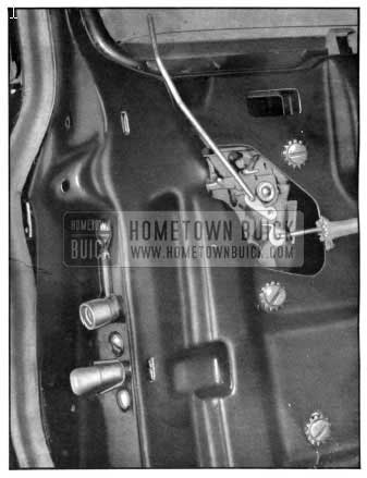
1950 BUICK DOOR LOCK REMOTE CONTROL
- Remove 1950 Buick door trim pad (see 1950 Buick Door Trim Pad Removal).
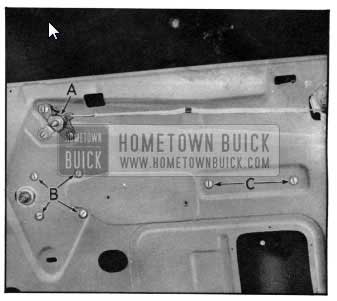
- Remove the three (3) remote control assembly attaching screws “A,” Figure No. 19, on door inner panel.
- On two-door styles, release the remote control connecting rod from its clip on the door inner panel, then disengage the end of the remote control rod from the door lock and remove complete assembly.
- To install, reverse this procedure. Note: Spindle rotates counter- clockwise on right hand doors and clockwise on left hand doors. On 1950 styles an insulated control rod is used instead of a flat link.
ADJUSTMENT
To take up end play in the connecting rod, loosen the three (3) screws “A” holding the regulator to the door inner panel and shift to desired tension.
1950 Buick Window Regulator Mechanism
1950 BUICK DOOR WINDOW REGULATOR
- Lower glass and remove door trim pad (see 1950 Buick Door Trim Pad Removal).
- Remove loading hole cover, also cemented covering from small circular hole in door inner panel.
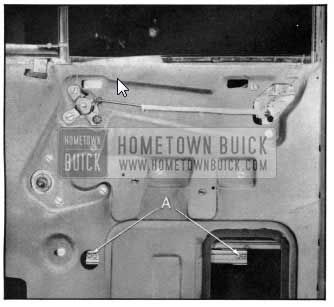
- Through these holes remove the four (4) window to sash channel cam screws shown at “A,” Figure No. 20, so as to disengage the window lower sash channel cam from the regulator mechanism.
- Remove the screws at “B” and “C,” Figure No. 19, that hold the regulator and stationary cam assemblies to the door inner panel.
- Regulator and cam may be removed through the loading hole.
- To install, reverse this procedure.
ADJUSTMENT
The outer screw hole of the regulator cam “C” is vertically slotted and the cam screw in this hole is normally moved down against the bottom of this slot. By loosening this screw, alignment of the up and down travel of the window glass in relation to the vertical center division channel and the glass channel on the door lock pillar can be made.
1950 BUICK DOOR WINDOW GLASS
- Lower window and remove door trim pad.
- Remove large loading hole cover and covering over small circular hole for access to screws “A.” Figure 20.
- Remove ventilator division channel.
- Remove the garnish molding retaining clips on the flanged surface of inner panel at lower window opening.
- Remove the two (2) screws “A” from each end of the sash channel to disengage the sash channel from the cam.
1950 Buick Window Lower Sash Channel
- Carefully raise the glass to an almost closed position and tilt inward, using care to work out one lower corner at a time so as not to cause damage.
- To install, reverse this procedure. Seal loading hole cover before installing trim pad.
1950 BUICK DOOR AND REAR QUARTER INSIDE BELT FINISHING MOLDINGS
- Remove the 1950 Buick door window garnish molding.
- Remove the inside safety locking rod knob.
- On front door s remove the ventilator regulator handle.
- Remove the belt finishing molding retaining screws at each end of molding.
- Remove the belt finishing molding by lifting upward to free it from the retaining clips.
- To install, reverse this procedure.
1950 BUICK DOOR WINDOW GARNISH MOLDING
- Remove cross-head screws from top and side of garnish molding.
- Remove garnish molding by grasping the upper horizontal section and pulling it toward the operator with a downward motion. Note: Garnish molding grommets slip over the two lower ends of the garnish molding.
- To install, reverse this procedure, using an awl if necessary to locate screw holes.
GLASS RUN CHANNEL
- Lower glass and remove garnish molding.
- Pry the upper section of the glass run channel to release clips from pinchweld at door header and remove upper section. Indicated by arrows Figure No. 21.
- To remove lower pillar section, remove door trim pad and loading hole cover, adjacent to lower end of glass run channel.
- Remove screw “A” retaining bottom of lower glass run section to pillar. Indicated in Figure No. 21.
- Carefully remove channel by pulling up through door window opening, using care not to dent stainless steel beading on channel.
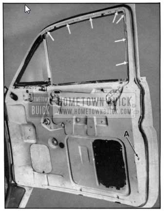
1950 Buick Door Glass Run Channel
- To install, reverse this procedure.
NOTE: Although it is possible to remove and install the lower glass run channel section without removing the trim pad and loading hole cover, it is suggested the operation be performed as outlined above to facilitate easy attachment of the lower glass run channel attaching screw “A.”
REAR DOOR STATIONARY WINDOW
REMOVAL
- Remove window garnish molding and door trim pad.
- Remove the rear door ventilator division channel indicated at “A,” Figure No. 22. (Similar to front door s.)
- With a putty knife, free the glass and rubber channel from sealer along rabbet around ventilator portion of opening. From inner side of door remove stationary glass and rubber channel assembly.
- If required, remove glass from channel.
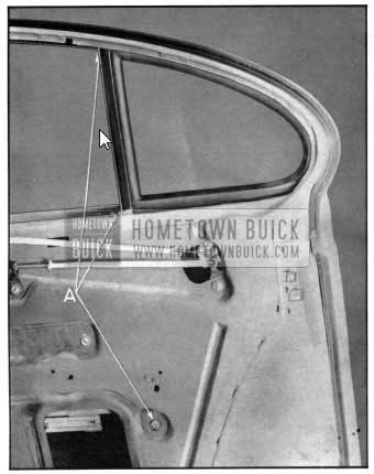
1950 Buick Ventilator Portion
INSTALLATION
- Prepare stationary window opening by cleaning off any old sealer from wall of rabbet around opening. Apply Weather strip Cement completely around rabbet wall of stationary glass portion of opening.
- Install a strong string or cord in rabbet groove of rubber channel. Then install glass and channel assembly into opening, with string accessible from outside body.
- With window in position, grasp string and pull from outside of body, so that lip of rubber channel slips over rabbet wall of window opening, then press assembly firmly into position.
- Install division channel and remainder of door hardware and trim parts.
- Apply “3M Weatherstrip Cement” between outer lip of channel and stationary glass completely around channel.
1950 BUICK DOOR LOCK
- With lock bolt in “down position” remove 1950 Buick door outside handle, door trim pad , and loading hole cover from door inner panel.
- Disconnect the door lock remote control connecting rod from lock by removing the remote control mechanism.
- Remove inside locking rod. To remove locking rod on rear doors remove the single bolt and washer holding the inside locking rod lever to the door inner panel.
1950 Buick Door Lock
- On front doors only, remove the glass run channel retaining screw on lower outer surface of door lock pillar facing.
- Remove the two (2) door lock screws from door inner panel facing and the three (3) door lock screws and washers from door lock pillar facing. See Figure No. 23.
- Remove the door lock by rotating out of position and extracting the lock down and out through the loading hole as shown in Figure No. 24. On front doors the lock must be dropped straight down to clear end of glass run channel.
- To install, reverse this procedure, first checking to see that bolt is in “down” position. On front doors the “U” shaped retainer on the lock housing must be threaded behind the lower end of the glass run channel during installation. This can be accomplished by pulling out slightly the lower end of the glass run channel. Seal loading hole cover prior to installing.
CAUTION: It is possible to seriously damage the door lock if the door is slammed shut after the latch has been accidentally or intentionally pushed into the “up” position.
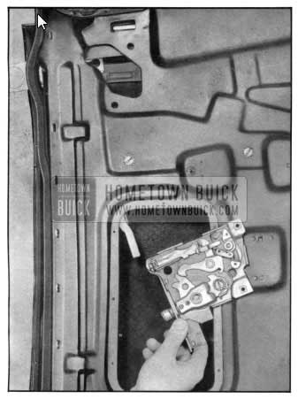
1950 Buick Door Lock Detachment
1950 BUICK DOOR LOCK STRIKER
REMOVAL
- With a pencil, scribe the position of the striker on the center or rear body pillar.
- Remove the two (2) attaching screws holding striker to pillar and lift out of position.
INSTALLATION
To install, place striker in position within the location designated by pencil marks, hold firmly, and reinstall attaching screws. Note: It is imperative that the door lock striker be installed in a level position so that it is in proper alignment with the lock bolt on the lock.
1950 Buick Door Lock Striker
ADJUSTMENT
Serrations on the back of the striker and striker adjusting plate, coupled with a movable anchor plate in the pillar, allow for an “in and out” or “up and down” adjustment for closer fit of the door to the door opening on the lock side.
1950 BUICK DOOR LOCK
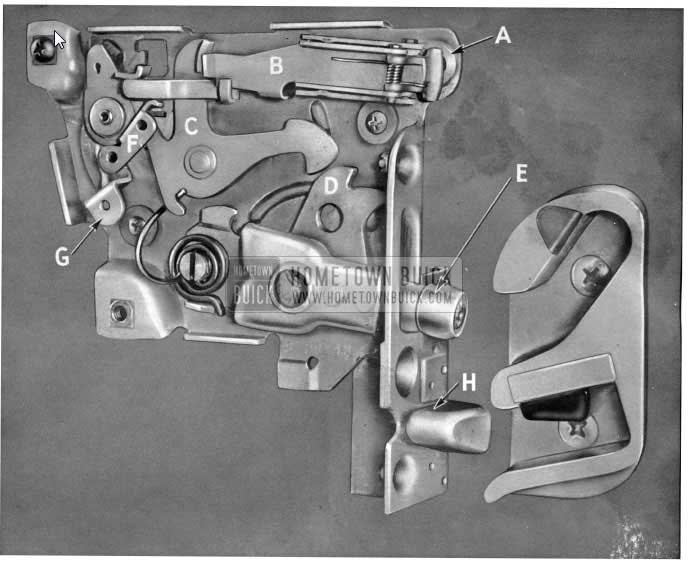
1950 Buick Door Lock and Striker Plate
The above illustration is a close-up view of the new 1950 Buick door lock and striker plate and shows at “A” the tumbler into which the door handle push button shaft fits to operate the trip lever “B.” The sliding action of this trip lever operates the hook lever “C” to disengage the latter from the multiplier lever “D,” releasing the bolt arm and roller “E” from its closed position in the bolt guide channel of the striker plate. When the door inside safety locking knob and the inside locking rod with attachment at “F” are operated to a locked position, the trip lever “B” is rotated to a lower position so as to pass under the engaging lug of the hook lever “c.” The remote control link rod attachment is shown at “G” and the wedge plate at “H.” Sedan 4-door coupe rear door locks have a “free-wheeling” feature.
The new 1950 Buick door lock striker plate shown adjacent to the lock in the above illustration has an upper and a lower guide channel for the door lock bolt and wedge plate respectively. As the door is closed, the lock bolt enters the upper guide channel and is forced upward until the locking mechanism is engaged at the top of the bolt travel. When the locking mechanism is tripped to unlock the door, the bolt is forced downward and out of the striker plate in the rever of the above. The bottom guide channel supplies the bumper action for the door lock wedge plate. This striker is installed on the body pillars with two (2) cross-recess head screws which enter into a floating anchor plate inside the pillar. Serrations on the back of the striker and adjusting plates allow for an in and out or up and down adjustment for normal fit of the door to the door opening on the lock side.
FREE WHEELING ADJUSTMENT ON REAR DOOR LOCKS
Free-wheeling rear door locks are safety locks which are designed so that a small free-wheeling linkage in the lock mechanism may be adjusted to allow the door inside remote control handle to be moved back ward and forward (free-wheel) without unlocking the door. The free-wheeling feature consists of a tie bar and free-wheeling trip lever incorporated into the lock. The trip lever can be shifted to put the lock either in free-wheeling position or in normal operating position. Access to this shifting free wheeling trip lever is gained through the lock bolt slot with the bolt in normal unlocked position at the bottom of the slot. A seven inch length of wire approximately 1/8″ in diameter, with a right angle hook 3/8″ long in one end, is the only tool needed to perform the free-wheeling adjustment. It is recommended that in performing this operation the lock attaching screw just above the bolt slot on the door lock pillar be removed and the trip lever sighted on an approximately horizontal line through this screw hole. Light from a small flashlight can be admitted through the bolt slot.
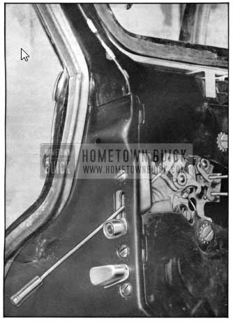
1950 Buick Rear Door Locks – Free-Wheeling
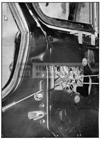
1950 Buick Rear Door Locks – Conventional Operation
To adapt the lock to “free-wheeling,” insert adjusting tool through lock bolt slot in door pillar facing, engage control lever, and push lever away from operator.
To adjust the lock from free-wheeling operation to non-free-wheeling operation, insert adjusting tool through lock bolt slot in door pillar facing engage control lever, and pull lever toward operator.
FRONT DOOR CHECK LINK
- With door open, remove the three (3) check link retaining bolts from the front body pillar.
- Remove 1950 Buick door trim pad.
- Remove cover from loading hole nearest check link.
- Remove the two (2) screws retaining the check link assembly to the door inner panel, and through the loading hole remove the check link assembly.
1950 Buick Front Door Check Link Assembly
- To install, reverse this procedure. First loosely attach check link assembly to both the door inner panel and the front body pillar, and after testing operation for proper alignment , tighten screws. Seal and install loading hole cover on door inner panel , and install door trim pad, inside handles, and garnish moldings.
ADJUSTMENT
A vertical adjustment is provided through slotted holes a t the check link to door inner panel attaching points.
REAR DOOR CHECK LINK
LINK ASSEMBLY
- Remove the center pillar trim.
- Remove screw holding link to center pillar and remove link.
- To install , reverse this procedure.
SUPPORT ASSEMBLY
- Remove door trim pad.
- Remove loading hole cover.
- R e move link support screws from door hinge pillar facing , noting the position of these screws in slotted holes before removal.
- Remove support assembly through loading hole.
- To install, reverse this procedure. Adjust as necessary and seal loading hole cover.
1950 Buick Rear Door Check
ADJUSTMENT
Loosen support assembly on door pillar facing, move support assembly laterally to decrease or increase respectively the hold open force, then tighten screws to hold in new position. Also, an emergency shim i s provided for installation to the center pillar with the link assembly. This shim also serves to increase the hold open force and at the same time limits the swing of the door.
1950 Buick Rear Door Check Assembly
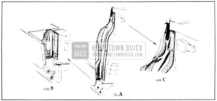
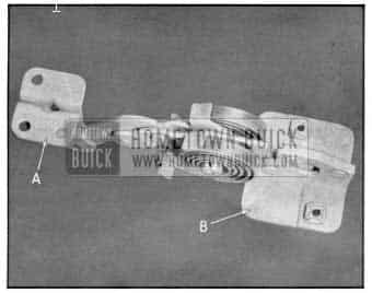
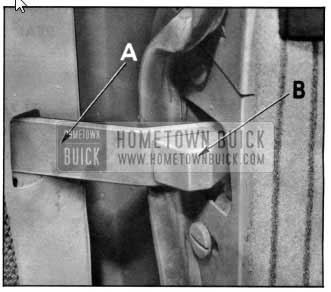
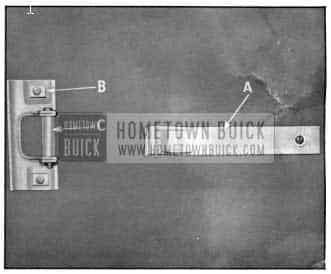
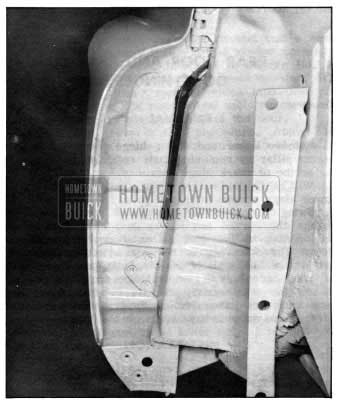
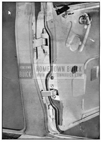
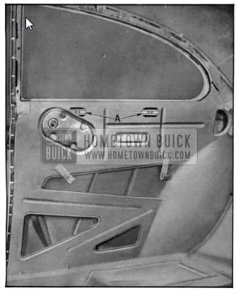
1950 Buick Front Door Sealing Strip
On later production the front body hinge pillar area from the belt line down on the new “40” Series bodies is protected by a bellow type sealing strip as illustrated in the drawing above. In the removal of front door s or adjustment of hinges, this sealing strip must be removed so as to gain access to the hinges. The edges of the sealing strip are cemented to the body metal, and in addition, fasteners are used for attachment. The drawings show the front edge of the door adjustment to the cowl side panel, with hood and front fender removed. Figure “A” shows the entire installation1 “B” the lower section of the sealing strip, and ‘C” the upper section. (See Door Removal Operations.)
FRONT DOOR AND FRONT DOOR HINGES
REMOVAL
- Detach check link at front body pillar by removing the three (3) check link to body pillar screws.
- Lift hood of car to expose cowl and pillar area at door to be removed. Access to the “bellows type” sealing strip and lower hinge on the door pillar is gained by reaching down through the opening between the front f ender and body pillar.
- With door in a closed position, use a claw type prving tool to detach the “rose bud” fasteners retaining the “bellows type” sealing strip to the side of the front body pillar, as shown in drawing Figure No. 32. Carefully loosen sealing strip from its cemented attachment on body pillar.
- From inside body with door in open position and adequately supported, remove the three (3) screws retaining each upper and lower hinge to the front body pillar and remove door. Scribe each hinge location prior to removing screws.
INSTALLATION
- Prior to installing door, use a scraper and oleum spirits to clean off old sealing cement from side of front body pillar and edge of sealing strip and dry thoroughly.
- Next, apply fresh “3M Weatherstrip Cement” along side of front body pillar and the edge of the sealing strip.
1950 Buick Front Door Hinge Installation
- Install 1950 Buick door to position by installing the three (3) door hinge to body pillar screws at each upper and lower hinge. Position each hinge to scribe marks. After installation check door for proper alignment.
- From outside of car, with hood raised, reach down through opening between fender and body pillar and adjust the sealing strip so that the fasteners on the sealing strip and body pillar are in alignment, then snap to place.
- To complete the operation, press all cemented surfaces of the sealing strip, firmly and evenly against the cowl side panel.
ADJUSTMENT
- An “up and down” adjustment is provided through slotted hinge attaching screw holes on the front body pillar. Loosen door hinge to body pillar screws and shift door as required.
- “In and out” adjustment is provided through slotted holes in the door pillar for attachment of hinges. Access to the upper hinge at door pillar is gained directly from inside door and body with door in open position. However, access to the lower door pillar hinge is gained from outside car through opening between fender and body pillar with hood raised. In this case reach down and pry off the circular disc clip retaining the lower end of the sealing strip to the snap fastener on the door pillar, then carefully loosen bottom portion of sealing strip to uncover lower hinge. When adjustment is completed, recement bottom of sealing strip to door after first cleaning off old cement. Replace clip over snap fastener, using new clip if necessary.
- Miscellaneous adjustments may also be made through the use of partial and full waterproof cardboard shims to correct conditions not covered in (1) and (2) above.
REAR DOOR AND REAR DOOR HINGES
REMOVAL
- Remove upper and lower hinge cover plates at center pillar by removing their retaining screws.
- Scribe or mark hinge locations.
- With a helper holding door, remove upper and lower hinge screws at center pillar.
- Swing the door towards the closed position to disengage the curved end of the door check link from its opening in the door pillar, then remove door. Note: The door can be removed at either the door half or the body half of the hinge straps.
- When necessary to remove hinges from door, first loosen the weatherstrip and its retainer from the door hinge area, then remove upper and lower hinge cover plates so as to have access to the hinge screws.
INSTALLATION
- If hinges have been removed from door, install them to door pillar prior to assembling door to body.
- With a helper, place door in position and insert check link in its opening in door pillar.
- Align hinges with scribe marks on center pillar and install one hinge screw in each hinge half. Then close door and check alignment. If alignment is correct, install the balance of hinge screws and tighten to place.
- Next, install the hinge cover plates. Apply “3M Auto Body Sealer” at the top and bottom of each hinge depression at area where cover plates are to be in stalled. In addition, apply a like amount on the pillar contacting surfaces of the cover plate itself. Then install each cover plate to effect a proper seal. CAUTION: When using sealing compound be careful of trimmed parts adjacent to hinge area.
1950 Buick Rear Door and Hinge Installation
ADJUSTMENT
In addition to shimming at door hinges, slotted hinge attaching screw holes provide an “in and out” adjustment at the center pillar and an “up and down” adjustment at the door hinge pillar.
REAR QUARTER WINDOW GLASS
- Remove the quarter window garnish molding (see Garnish Molding).
- Remove the window regulator handle (see Inside Handles).
- Remove the belt finishing molding below window opening (see Belt Finishing Molding).
- Release and turn back quarter trim pad sufficiently to expose rear quarter inner panel.
- Raise window and through the cutouts in inner quarter panel indicated at “A” Figure No. 35 remove the four (4) screws from the regulator cam.
- Grasping top edge of glass, lift and tilt glass in ward to free it from its channel and remove from inside of body.
- To install, reverse this procedure.
1950 Buick Inner Rear Quarter Construction
FRONT DOOR LOWER REVEAL MOLDING
(See Figure 36)
- Remove 1950 Buick door trim pad.
- Through the loading holes on door inner panel, remove the four (4) window to sash channel cam screws and lower window below sill of window opening.
- Remove door window ventilator.
- If applicable, remove rivet attaching rear end of molding to flange of door at lock pillar.
- Remove screws as illustrated in Figure No. 36 attaching molding to retainers at lower opening. Lift up to remove the lower molding which consists of two sections, the forward section overlapping the rear section.
- To install, reverse this procedure. Apply “3M Autobody Sealer” along inner curled lip of molding prior to installation.
1950 Buick Rear Quarter Lower Reveal Molding Attachment
REAR DOOR LOWER REVEAL MOLDING
(See Figure 36)
- Remove 1950 Buick door trim pad.
- Remove window lower sash channel cam screws and lower the window below sill of window opening.
- Remove screws as indicated in Figure No. 36 securing molding to retainers at lower opening. Lift up to remove lower molding which laps over the lower portion of the rear reveal molding surrounding the stationary glass opening of the door.
- To install, reverse this procedure. Apply “3M Autobody Sealer” along inner curled lip of molding prior to installation.
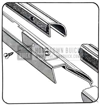
FRONT DOOR BELT MOLDING
(See Figure 37)
- Remove front door lower reveal molding.
- Remove screws and reveal molding retainers along lower opening as indicated in Figure No. 37.
- Remove belt molding.
1950 Buick Belt Molding Attachment
- To install, reverse this procedure. Apply “3M Autobody Sealer” along lower inner curled lip of belt molding and to molding retaining screw holes in door outer panel along lower opening prior to installing belt molding.
REAR DOOR BELT MOLDING
(See Figure 37)
- Remove both lower sections of rear door lower reveal moldings.
- Remove screws and reveal molding retainers along lower opening as indicated in Figure No. 37.
- Remove belt molding.
- To install, reverse this procedure. Apply “3M Autobody Sealer” along lower inner curled lip of belt molding and to retaining screw holes in door outer panel along lower opening prior to installing molding.
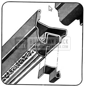
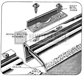
1950 Buick Upper Reveal Molding Attachment On Front Doors
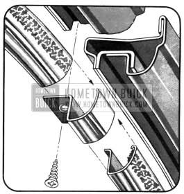
1950 Buick Upper Reveal Molding Attachment On Rear Doors
FRONT DOOR UPPER REVEAL MOLDING
(See Figure 38)
- Remove front door lower reveal molding.
- Remove ventilator rain deflector.
- Remove upper section of glass run channel.
- Remove upper reveal molding clips from pinchweld of door header and remove molding.
- To install, reverse this procedure. Apply “3M Autobody Sealer” along inner curled lip of molding as indicated prior to installing upper molding.
REAR DOOR UPPER REVEAL MOLDING
(See Figure 39)
- Remove upper section of glass run channel along door header.
- Remove screw retaining escutcheon to header at upper forward edge of stationary glass.
- Remove molding spring clips from pinchweld around header, and remove molding.
- To install, reverse this procedure. Apply “3M Autobody Sealer” along inner curled lip of molding as indicated prior to installing molding.
REAR DOOR WINDOW REAR REVEAL MOLDING
(At Stationary Window Opening) Removal
- Remove stationary window assembly.
- Remove rear door lower reveal molding.
- Remove screws securing rear reveal molding to retainers at lower stationary window opening.
- Remove upper reveal molding escutcheon by removing single screw (check on screw location to see if it affects glass run channel or if it is same screw used at upper division channel). Remove rear reveal molding.
- To install, reverse this procedure. Apply “3M Autobody Sealer” along inner curled lip of molding prior to installation.
Leave A Comment
You must be logged in to post a comment.