FRONT SEAT AND SEAT ADJUSTER
Note: The 1950 Buick front seat cushion cannot be lifted out.
- Remove the 1950 Buick front seat side panel, including extension.
- Remove the two (2) seat adjuster to floor pan bolts from each of four seat adjuster supports.
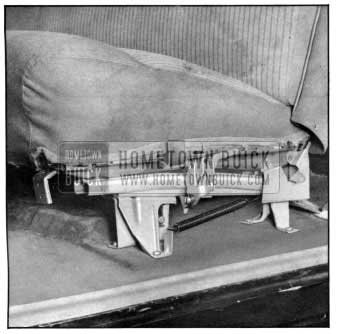
1950 Buick Front Seat Adjuster
- Remove the 1950 Buick front seat assembly from body with seat adjuster unit attached.
- Remove seat adjuster assembly from seat as follows: Detach the locking rod from the locking rod clip on the center bar of the seat frame. The seat front and r ear attaching bolts are installed in an inverted position through the top of the upper channel. To remove the front bolt, push the adjuster to the rear and remove exposed bolt. To remove rear bolt, push adjuster forward and remove bolt. Remove center attaching bolt and remove seat adjuster assembly.
- To install, reverse this procedure.
ADJUSTMENT
The slotted attaching bolt holes of the seat adjuster supports provide lateral or sideward adjustment to permit alignment of adjuster units on each side of the body.
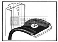
ROBE RAIL CORD
- Remove outer cross-head screw from escutcheon on each end of robe cord , as shown in the picture, and remove cord.
- To install, reverse this procedure. The escutcheons may be removed if desired by removing the remaining inner screws.
Note: The robe cord and escutcheon retaining screws also secure the upper portion of the 1950 Buick front seat back trim panel to the seat back frame.
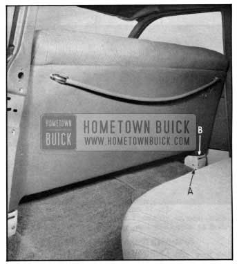
1950 Buick Sedan Front Seat Back
1950 BUICK FRONT SEAT SIDE TRIM PANEL
REMOVAL
Note: The 1950 Buick front seat cushion cannot be lifted out.
- Loosen set screw and remove seat adjuster control handle from left side of seat.
- Remove two screws at each curved end of the seat side trim panel, disengage the retaining tab on inner surface of panel and lift the complete assembly out of position.
- Note: The side panel extension “A,” Figures No. 41 and 42, is a separate part and comes off with the complete side panel when rear screws are removed.
- To install, reverse this procedure.
1950 BUICK FRONT SEAT BACK TRIM PANEL
REMOVAL
- Remove 1950 Buick front seat side panel and adjuster handle.
- Remove robe cord escutcheon screws retaining upper portion of seat back to seat back frame.
- At the bottom of seat back, at each lower corner indicated at “B,” Figure No. 41, remove the retaining screw (one each side) anchoring the lower portion of seat back to seat frame. Lift seat back trim panel out of position and remove.
Note: On split back seats, these latter screws are accessible along lower edge of seat back trim panel indicated at “C,” Figure No. 42.
- To install, reverse this procedure.
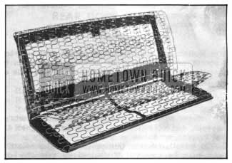
1950 BUICK FRONT SEAT BACK (METAL FRAME)
REMOVAL (Full Width Seat)
- Remove 1950 Buick front seat adjuster handle and seat side trim panel, also seat back trim panel.
- On 4-door style seats, remove the four (4) bolts at each lower rear side, retaining the legs of the metal seat back to seat bottom cushion frame, indicated at “B,” Figure No. 41.
- Lift seat back assembly upward so that legs of seat back disengage from channel sections on seat cushion frame.
- To install, reverse this procedure.
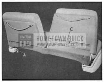
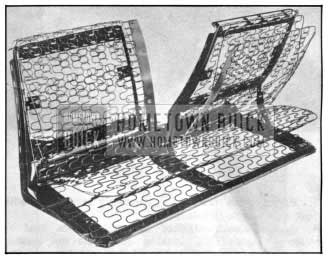
1950 Buick Split-back Type Seat Back
1950 BUICK FRONT SEAT BACK (METAL FRAME)
REMOVAL (Split Back Type Seat)
- Remove 1950 Buick front seat adjuster handle and seat side trim panel. It is not necessary to remove seat back trim panel on split back seat,
- At the bottom center of the curved center hinge arms, remove the cotter pin and disengage the hinge pin anchoring both left and right seat backs to the center of the cushion frame.
- At the bottom of the outer curved hinge arms of the seat back, remove the spring retaining clip from end of hinge pin. (Hinge pin is stationary at this point and cannot be removed.)
- To remove, lift up seat back at center and move it sidewise to disengage outer hinge arm from the stationary hinge pin.
- To install, reverse this procedure.
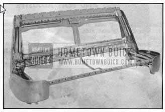
1950 Buick Sedan Front Seat Metal Frame
1950 Buick Combined Seat Frame and Zig-zag Spring Assembly
1950 Buick Combined Seat Frame and Zig-zag Spring
1950 BUICK FRONT SEAT CUSHION TRIM
REMOVAL (4-DOOR DYNAMIC COUPE)
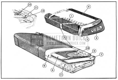
1950 Buick Diagram of Front Seat Cushion Trim Installation
- Remove entire 1950 Buick front seat assembly from body.
- Remove 1950 Buick front seat back from the assembly and place cushion portion upside down on a clean bench.
- Remove hog rings holding bottom rear facing indicated at (1) to spring and frame. Remove loose wadding (2) from back of seat frame.
- Remove hog rings securing end facing to slots in seat frame at (3). Also remove hog rings holding end listing to spring at (4).
- Remove hog rings retaining front facing at (5) to slots at rear of front frame bar.
- Turn cushion over, turn back trim cover and remove cotton pad (6), cotton batts (7) and (8) and latexed hair pad (9).
- Remove hog rings securing top rear facing to spring a t (10).
- Remove hog rings holding cotton pad to spring at (11). If necessary, the wire insulator may be re moved by disengaging hog rings as indicated at (12).
INSTALLATION
Note: Prior to attaching trim with hog rings, make sure all listing wires are installed in the pockets in the skirt of the 1950 Buick front seat cushion.
- Replace insulator if removed. Secure at front, rear, and at each corner with hog rings.
- Attach cotton pad to spring at (11) with eight hog rings along each front and rear edge and three along each end (also see insert Fig. 46).
- Hog ring the top rear facing to spring with thirteen rings as shown at (10) in insert.
- Place latexed hair pad over foundation pad at (9) and tuck snugly at rear.
- Place a cotton batt over hair pad at each end (7) and along front (8). Batt is opened one-third.
- Place cotton pad (6) over batts and foundation pad. Tuck snugly at rear.
- Turn cushion upside down and hog ring the front facing at (5) to slots at rear of front frame bar with fourteen rings.
- Secure each end facing to slots in cushion frame with six hog rings at (3). Also apply two hog rings at end of each facing.
- Hog ring the end listing at (4) to the spring with three rings.
- Apply wadding to back of cushion frame at (2) and proceed to secure the bottom rear facing to spring with eight hog rings and to frame with two hog rings at each end as shown at (1).
- Assemble front seat back assembly to seat cushion and install complete front seat assembly to body.
CENTER PILLAR TRIM
- Carefully loosen headlining along side roof rail directly above top end of center pillar.
- Turn up headlining and loosen the headlining saw tooth retainers directly underneath, then detach center pillar upper trim along this area.
- With a suitable flat bladed tool, pry loose the center pillar trim from its ratchet nail attachment on the center pillar as indicated in Figure No. 47.
- To install, reverse this procedure.
1950 Buick Center Body Pillar Trim Assembly
REAR SEAT BACK
- Remove rear seat cushion.
- From inside body at bottom of rear seat back and on wheelhouse, straighten out the metal tabs securing bottom of seat back along this area.
- Pull out the seat back at the bottom, and lift up to free from retainer at the top.
- To install, reverse this procedure.
REAR QUARTER ARM REST (2-DOOR DYNAMIC COUPE)
- Remove rear seat cushion and cushion back.
- Carefully loosen arm rest material from cement and retaining tabs at wheelhouse area indicated at “A,” Figure No. 48.
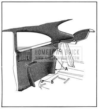
1950 Buick Rear Quarter Trim Installation
- Remove the single screw and washer at “B” securing arm rest bracket to floor pan.
- Disengage arm rest from lower retaining tab on wheelhouse and lift straight up to free from its retaining brackets.
- To install, reverse this procedure. Use “3M Trim Cement” to recement material to wheelhouse.
REAR QUARTER TRIM (2-DOOR DYNAMIC COUPE)
- Remove rear seat cushion, cushion back, and rear quarter arm rest (see Rear Quarter Arm Rest Removal). Also loosen and roll back rear floor carpet in area of lower rear quarter trim.
- Remove rear quarter garnish and belt finishing moldings (see Door and Rear Quarter Garnish and Belt Finishing Moldings Removal).
- Remove rear quarter window regulator handle .
- Loosen cemented portions of trim at wheelhouse and floor areas. Also free top rear portion of trim panel from tabs which also secure headlining at “c,” Figure No. 48.
- Pry loose the front edge of the trim assembly along “D” where secured with binding strip nails, and remove.
- To install, reverse this procedure. Recement material to floor and wheelhouse with “3M Trim Cement.”
Leave A Comment
You must be logged in to post a comment.