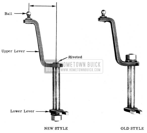
This section of the 1950 Buick Service Bulletins is made to support you to maintain the 1950 Buick Clutch & Transmission. To accurately position the Dynaflow shift control valve in the valve body, the distance from the upper lever ball to the shaft centerline must be carefully maintained. The upper valve operating lever and shaft have now been made a permanent assembly by riveting this lever to the shaft. This will eliminate any variation in the distance from the upper lever ball to the shaft (also reverse overshift due to lever position) when the parts are reassembled in the field. The lower lever will now be fastened to the shaft with a 5/16-24 nut. See Figure 11. The new upper lever and shaft and new lower lever can be assembled in any previous servo body.
1950 Buick Valve Operating Lever and Shaft
Effective with Dynaflow transmissions F-73 (40-50) and G-73 (70) the size of the bleed hole in the pressure regulator valve has been reduced from .047″ to .040″. This change was made to eliminate the buzzing noise in Park and Neutral.
Parts information is as follows:
Group 4.273, Part No. 1344037, Valve, Pressure Regulator
This valve will supersede the 1333632 valve for service in all prior series Dynaflow transmissions.
Approximately May 1st, two important design revisions to be made in the Dynaflow transmission, will change the series identification numbers to C -for 70 jobs and E -8 for 40-50 jobs. These revisions are as follows:
A. Elimination of the Low Band Anchor Piston
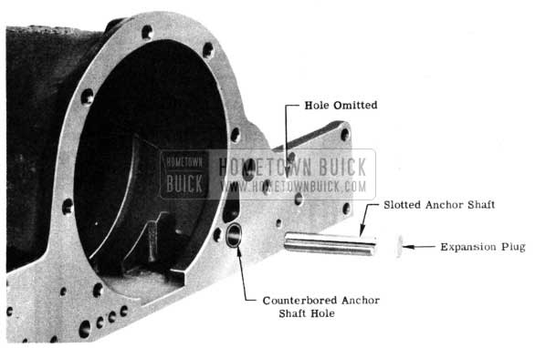
The low band anchor piston, spring, shims, lever and shaft will be eliminated and the Low to Drive shift timing will be controlled by orifices in the accumulators. The anchor end of the low band will continue to be restrained by the same type strut as formerly used, in conjunction with a new slotted anchor shaft which has been relocated to compensate for elimination of the anchor lever. The anchor shaft hole in the transmission case, in addition to being relocated, is counterbored to accommodate an expansion plug which will prevent oil from the high 1950 Buick clutch line in the reaction flange leaking by the anchor shaft into the case. These changes are shown in Figure 12. Note that the old and new type transmission cases are not interchangeable.
1950 Buick Low Band Anchor Piston
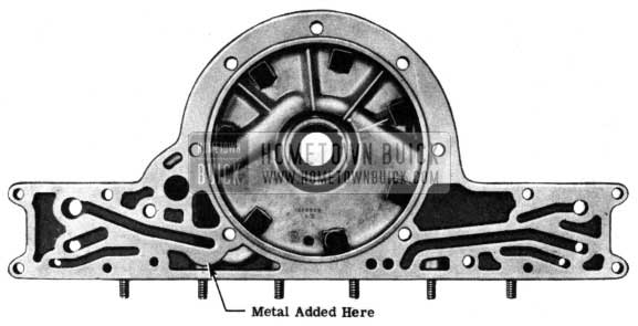
In conjunction with the new transmission case, the reaction flange has been redesigned to prevent oil from leaking into the lightening pocket below the high 1950 Buick clutch apply line and into the transmission case through the cut-out at the bottom of the low band opening. This is accomplished by adding metal to the face of the reaction flange, adjacent to the counterbored anchor shaft hole in the case, as shown in Figure 13.
1950 Buick Dynaflow Counterbored Anchor Shaft
The new flange must be used with the new transmission case but can also be used with past style cases on prior series transmissions.
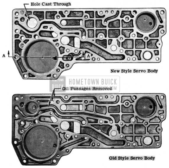
A comparison of old and new type servo bodies is shown in Figure 14. As seen in the photo, the previous low band anchor piston bore will be cast through the servo body in order to facilitate oil drainage to the oil pan. The servo body is strengthened by ribbed construction in the area formerly occupied by the oil passages indicated by arrows in Figure 14.
1950 Buick Dynaflow Servo Body
In addition, the Allen head screw located between the reverse servo and low band anchor piston housings, on third type servo bodies used with A-42,000, B-1 and up, Series transmissions, has been changed to a hex-head cap screw slightly greater in length.
In conjunction with the new type servo body, the servo spacer plate lower gasket has been redesigned as shown in Figure 15. The new gasket must be used with the new servo body, but can also be used with prior type servo bodies.
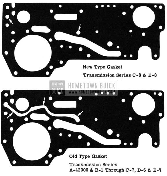
1950 Buick Dynaflow Gasket
Elimination of the anchor valve as a shift timing device has resulted in improvement and simplification of both accumulators. (See Figure 16.)
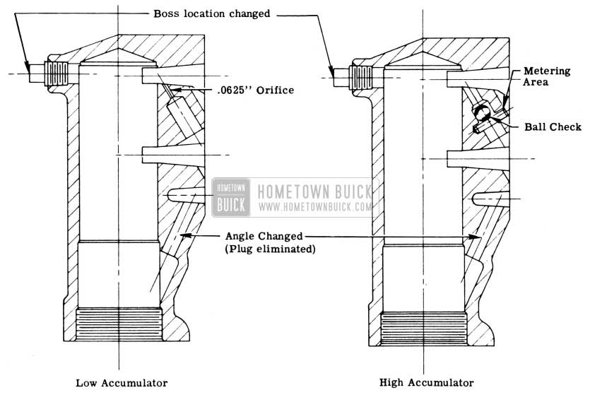
1950 Buick Dynaflow Low and High Accumulator
The two right-angle drilled holes, which were used to vent the under sides of the accumulator pistons, have been replaced by a single angle drilled hole. This eliminates any leakage at this location.
The new high accumulator (Figure 16) operates in the same manner as the old unit, except that the dump valve and spring have been replaced by a ball check valve. The difference in diameters of the pin hole and ball retaining pin acts as a metering orifice to control the rate of engagement of the high 1950 Buick clutch. The new high accumulator can be used on all prior series Dynaflow transmissions.
The new low accumulator (Figure 16) has no ball check j dump valve or spring, but controls the shifts by routing the oil through a .0625″ metering orifice during apply and release of the low band. The new low accumulator cannot be used on any prior series transmissions.
You will note from Figure 16 that a boss, tapped for a 1/8 pipe thread fitting, has been located at the upper front side of both accumulators. This will facilitate pressure checks without removing the floor pan. The most convenient method of making accumulator pressure checks is shown in Figure 17.
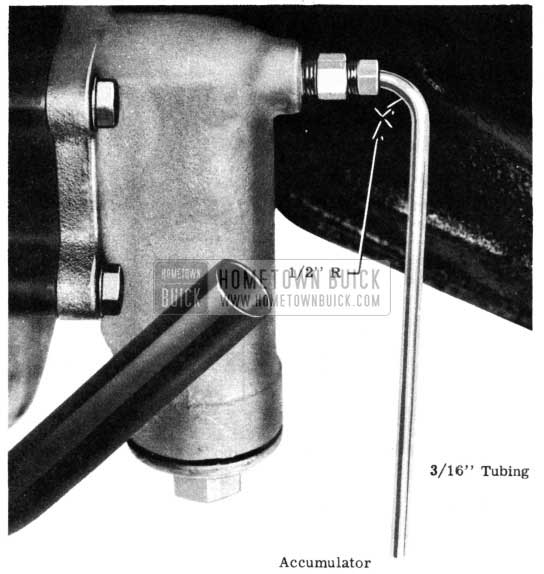
1950 Buick Dynaflow Accumulator and Tubing
Whenever installing accumulators, use the tightening sequence shown in Figure 18. This method will improve the accumulator gasket seal.
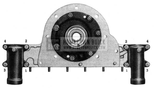
1950 Buick Dynaflow Accumulator Installation
B. Two Stage Reverse Servo Piston
A new two-stage reverse servo piston, designed to soften the engagement of the reverse band, is shown in Figure 19.
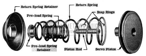
1950 Buick Two Stage Reverse Servo Piston
A ball check valve and metering hole, in parallel 9 have been added to the reverse apply line in the servo body and the reverse servo well has been deepened approximately 1/4″ to provide additional travel for the servo piston. In addition, the two right-angle drilled holes which previously supplied oil to the reverse servo have been replaced by a single angle drilled hole, thus eliminating the plug. These additional changes in the servo body are shown in Figure 20, which is Section A-A of Figure 14.
When the shift to reverse is made, the ball check valve is on its seat and oil is fed to the reverse servo through the orifice only (Figure 20).
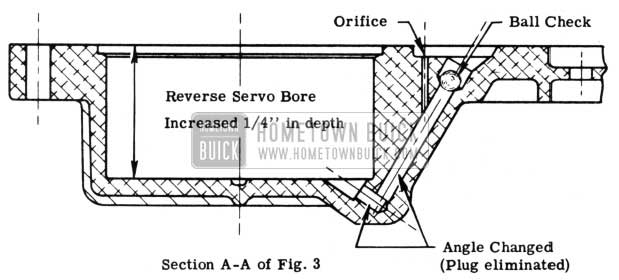
1950 Buick Reverse Servo Bore
The first movement of the reverse servo assembly takes up the clearance between the band and reverse ring gear. Next, the pre-load (cushion) spring applies a load of about 70 pounds to the apply lever as it starts being compressed by the servo piston. As the piston continues to move upwards the load continues to increase until the reverse ring gear is stopped from spinning. In this manner the pre-load spring, together with the orifice, increases the time of applying the reverse band and causes a much softer engagement of the band. The servo piston then applies the full force of the oil to the band as the upper end of the piston stem comes in contact with the pre-load spring retainer.
When the transmission is shifted out of reverse the ball check valve (Figure 20) is lifted off its seat, permitting a fast release of the oil under the servo piston.
The two-stage reverse servo piston assembly cannot be used with any prior series servo body.
Effective with Dynaflow transmission numbers F-100 (40-50) andG-100 (70) the primary pump bolt head thickness has been reduced from 1/4″ to 3/16″ to facilitate manufacturing the part. The 1/4″ thick head bolt will be carried by the Parts Department for replacement of bolts on transmissions built prior to this change. The 3/16″ or the 1/4″ thick head bolts may be used on transmissions built before or after this change providing the head thickness of all the bolts used are the same. If this is not done, an out-of -balance condition will result since the bolt weights are not the same.
The early type units built prior to transmissions C3, D3 and E3, which required both short and long primary pump cover bolts, will continue to be serviced with the 1/4″ thick head short and long bolts to maintain balance. (See 1948-49-50 Dynaflow Transmission Shop Manual, Section 4, paragraph 18 (e), page 45.)
The new 3/16″ thick head bolt will be serviced as Group 4.115, Part No. 1344008, Bolt, Primary Pump-Long.
To eliminate the tendency of some Dynaflow Transmissions to leak oil from the breather tube, a “U” shaped spring steel baffle has been incorporated in the breather body. The baffle permits free circulation of air, but prevents oil from being thrown against the open end of the breather tube.
The baffle will be carried by the Parts Department for installation if, Dynaflow Transmissions carrying the new type breather assembly built prior to adoption of baffle in production. When the breather and baffle assembly is installed in the transmission, the legs of the baffle should be in line with the transmission centerline, and fit tightly in the breather body.
This change will go into production approximately May 5. 1950. Parts Department will have the baffle in stock approximately June 1, 1950. Baffle is available under Group No. 4.319, Part No. 1342976.
Approximately April 25th, the converter primary and secondary stators, and secondary pump, used in Series 70 Dynaflow transmissions will be redesigned. The new stators and pump will have fewer vanes than present styles but part numbers will remain unchanged and the new design parts can be used in any prior Series 70 Dynaflow transmission.
Affected parts are as follows:
Group Part No. Item Old Part No. of Vanes New Part No. of Vanes
4.116 1335073 Stator, Converter Secondary 23 21
4.119 1335074 Stator, Converter Primary 25 23
4.110 1335075 Pump, Converter Secondary 31 19
Two important changes have recently been made in the Dynaflow re action shaft flange. In the first of these (see Figure 21) the flange was redesigned to provide a drain channel, across the lower front face, which interconnects the adjacent lightening pockets. This drain leads oil back into the transmission case and eliminates the possibility of external oil leaks in this area. The above design change was effective with transmissions F-73 (40-50) and G-73 (70). The part number has not been changed and the redesigned flange can be used for service re placement in all previous transmissions.
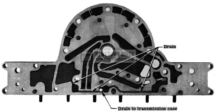
1950 Buick Dynaflow Reaction Flange and Front Pump Cover Gasket
In connection with this change, the front pump cover gasket was re designed to provide sealing area at the converter oil feed passage by increasing the stock between the lower side of the gasket and the cutout for the converter feed line. Details of this change are readily apparent in Figure 22.
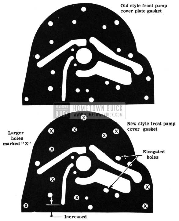
1950 Buick Dynaflow Front Pump Cover Plate Gasket
In addition, certain holes in the gasket which pass over studs on the reaction shaft flange have been elongated or increased in size to prevent gasket distortion during assembly. The new gasket can be used with prior transmissions and must be used with the reaction flange previously described. For this reason it was introduced in production about July 12, and will be found on some transmissions not equipped with the new style reaction flange, as well as on all transmissions having the redesigned flange. The new gasket will be serviced as follows:
Group 4.225, Part No. 1343202, Gasket, Front Pump Cover
The second design change in the reaction shaft flange was effective with transmissions F-114 (40-50) and G-114 (70). This involved use of new 1950 Buick clutch oil sealing rings having a butt joint instead of the interlocking joint formerly used. In order to facilitate assembly of the high-low brake drum over the new rings, the diameter of the land between the two rings was increased to conform with the diameter of the two outside lands. The high 1950 Buick clutch oil feed groove was increased in width and located centrally between the ring grooves. All of these changes are shown in Figure 23.
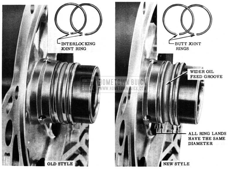
1950 Buick Dynaflow Oil Feed Grove
As with the first change described, the part number of the reaction shaft flange assembly has not been changed. The latest type flange can be used on any Dynaflow transmission in conjunction with either the butt or interlocking joint type sealing ring, but requires use of the new Part No. 1343202, Front Pump Cover Gasket. The butt joint ring, however, must not be installed on any other style reaction flange, and will not be carried by the Parts Department for service at the present time.
The following is a reprint of Special Service Letter – Dealer No. 84, dated August 1, 1950.
The method of assigning transmission serial numbers has been changed to make it possible to determine the exact day a transmission has been built. This change has been made principally to assist the Engineering and Manufacturing Division in investigating Service complaints. One number will apply to one days production of transmissions only. The 40-50 Series numbers will begin as follows: F-1, F-2, F-3 …. to F-999 and continue with H-1, H-2, etc. The 70 Series numbers will be gin as follows: G-1, G-2, G-3 …. to G-999 and continue with J-1, J-2, etc.
Engineering changes which affect the interchangeability of parts will be assigned the succeeding number in the sequence, regardless of the time of day the change is made. The Service Department will be notified of these changes by bulletin and the first identification number carried by the transmissions incorporating the change.
The number will still be stamped on the left side of the transmission behind the high accumulator, but now will be found on the aluminum re action shaft flange instead of the transmission case. If the reaction shaft flange should be changed, for any reason, the same identification should be stamped on the new part.
IMPORTANT: All Product Reports and AFA’s submitted on Dynaflow transmissions must show the transmission identification number.
This change will appear on all Dynaflow Transmissions approximately July 31, 1950.
A recent change has been made in the 1950 Buick clutch pedal and controls on Series 40 and 50 Synchromesh jobs affecting the pedal and equalizer design and also providing modifications in the frame. In connection with this change, the over-center type clutch release spring has been eliminated and the 1950 Buick clutch release rod has been shortened one inch.
On a few jobs, immediately after this change became effective, the release rod was threaded for a distance of 1 3/4″ instead of the correct 2 3/8″. These rods will not provide proper pedal adjustment after the 1950 Buick clutch facings have become worn and it will be necessary to chase the threads an additional 5/8″ (total of 2 3/8″) before making adjustment. A 3/8″-16 American National die should be used.
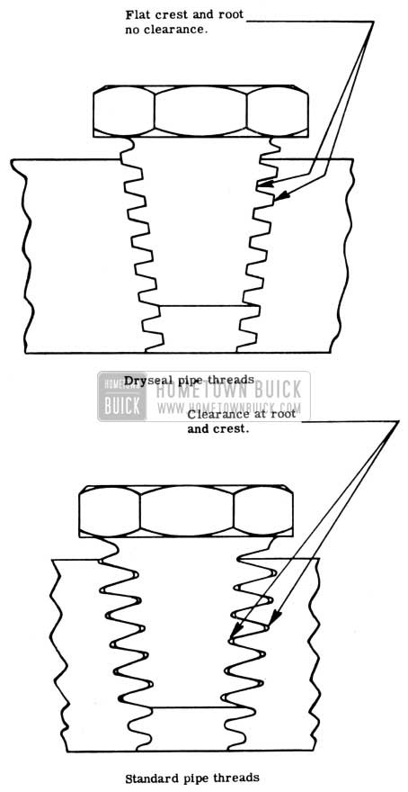
Reports from the Field indicate that some confusion exists in correcting occasional oil leaks at the primary pump cover drain plug holes. The thread form in these two tapped holes is known as a 1/8-27 American National Taper Pipe Dryseal thread, which is a recognized thread standard developed specifically for positive sealing at high pressures without the use of a sealing compound. The Dryseal thread seals, not only on the sides of the thread as does the standard form, but on the root and crest as well. The new style hex head 1/8 pipe plug, Group 8.971, Part No. 8608680, released for the Dynaflow Transmission, is made with the Dryseal thread form. The accumulator bodies, reaction shaft flange, and rear bearing retainer also use the Dryseal thread form.
The difference between the Dryseal threads and the standard pipe threads is shown in exaggerated form in Figure 24.
1950 Buick Dynaflow Primary Pump Cover Drain Plugs
It is readily seen that the Dryseal threaded plug or standard plug can be used in a Dryseal tapped hole. However, the Dryseal plug cannot be used successfully in a standard tapped hole without danger of leakage. The primary pump cover holes have been threaded with Dryseal taps since approximately April 1st. Extreme care should be exercised when removing the old square-headed plug to prevent distortion or mutilation of the threads. If re-tapping of the holes is required, it should be done with a Dryseal tap only.
We have made arrangements for dealers to order the tap directly from the manufacturer, as follows:
Order from: Winter Brothers Company, Rochester, Michigan, Attention: Mr. R. H. Stitt
Description: 1/8-27 High Speed Commercial Ground Taper Dryseal Pipe Tap
Price: $1.76 net – postpaid
Terms: Cash or C.O.D.
As a suggestion, we feel that it is advisable to re-tap any of the former type pump covers in your stock with a Dryseal tap and install the new hex head plugs, F-art No. 8608680. This could also be done on any transmissions that may come into your dealership for service or overhaul.
The allowable runout of the primary pump hub as specified in Section 7, Paragraph 39, Step b 4 of the Dynaflow Shop Manual, has been increased from .007 ” to .012″. The flywheel face runout should be checked before assembling the primary pump and cover to the flywheel to check hub runout.
The method of inspecting front and rear pump clearance is shown in Section 7, Paragraph 34, Step b. The clearance between the drive gear and the crescent as shown in Step c 6 of the above, has been changed from .006″ – .009″ and .004″ – .006″, to .007″ – .014″ for the front pump and .007″ – .011″ for the rear pump. The method of measuring the clearances is shown in Figure 25.
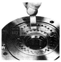
1950 Buick Dynaflow Limits
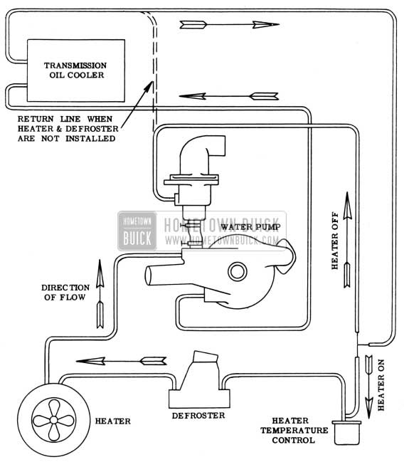
In the first 1950 Series 40 the oil cooler, heater and defroster hoses were connected so that the flow was from the temperature control to the heater and then to the defroster. These connections are shown in figure 61 in the 1948-49-50 Dynaflow Shop Manual.
Shortly after the start of Series 40 production the hose connections were changed to avoid interference with other parts. In later Series 40 and all Series 50-70 the hoses are connected so that the flow is from the temperature control to the defroster and then to the heater as shown in Figure 26.
1950 Buick Dynaflow Transmission Cooler
We are receiving some complaints of faulty clutch operation when a 1950 Buick clutch replacement is made in 1950 Buick Series 70 jobs equipped with Synchromesh transmission. All service personnel should be instructed to check clutch finger height before making installation. Although this adjustment is made at the factory, careless handling during shipment may affect adjustment and cause faulty operation.
The 1950 Buick Clutch Release Equalizer Return Spring, Group 0.790, Part No. 1342153, used on Series 40-50 Synchromesh after jobs has been shortened in production from 9.46″ to 7 .46″.
The Parts Department has advised us that they are scrapping their entire stock of 9.46″ springs and all future orders will be filled with the new shorter spring.
Effective immediately, the converter pressure regulator valve and spring should be omitted from any Dynaflow Transmission removed for repairs. Engineering tests have shown that the pressure resulting from the lube pressure regulator valve, plus the back pressure from the cooler, provides ample pressure in the converter for satisfactory operation.
Leave A Comment
You must be logged in to post a comment.