A sponge rubber 1950 Buick steering column dash pad is now being used in production. This replaces 1950 Buick steering column dash pad shield assemblies, Part Nos. 1339957, 1341744 and 1341745.
Should the need arise for installing the new pad in service, the following procedure should be followed:
- The dash insulator (1950 Buick steering column) retainer, steering column dash pad, rear, and the steering column dash pad shield assembly should be removed – the shield assembly may be scrapped.
- The dash cutout tie bar should be removed, and a new (Part No. 121893) bolt driven through the clinch nut from the engine side with a plain washer (Part No. 120392) under bolt head.
- To install the new 1950 Buick steering column dash pad, it is necessary to remove the steering wheel, direction signal control lever, shift lever and quadrant (when Dynaflow is specified), as well as disconnect steering column mast jacket from instrument panel. To facilitate installation, loose n steering gear housing to frame bolts.
- The wiring harness emerging from the 1950 Buick steering column mast jacket must be disconnected from the fuse block. Care should be taken to note the exact location of six wires so that proper reassembly will be made.
- The new pad may then be slipped over the top of 1950 Buick steering column and slid down to its proper position at the dash, at which time the steering column should be re-assembled to the instrument panel. (See Figure 34).
1950 Buick Steering Column Dash Pad
Retighten steering gear housing to frame bolts.
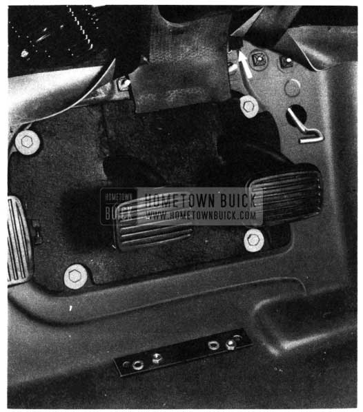
- The dash cutout tie bar should then be placed over the bolts (See Step No. 2) so that the bottom of the rubber pad is between the tie bar and pedal plate, and tightened down using lock washer and 1/4-20 nut (Part No. 134551). If the interference between the reinforce rent around the dash cutout and the tie bar is such that the nut cannot be started, the lower corners of the reinforcement may be cut with tin snips. (See arrow on Figures 34 and 35). If the nut will start, the reinforcement will buckle enough as the nut is tightened to permit a good seal. (Figure 35 shows tie bar installed.)

1950 Buick Steering Column Dash Pad Bar
- The 1950 Buick steering column dash pad, rear and the dash insulator (1950 Buick steering column) retainer should then be re-installed.
- Reinstallation of direction signal control lever, shift lever, quadrant (when used) and steering wheel, as well as reconnecting the direction signal wires to the fuse box, completes the job. Care should be taken to connect the wires to the proper terminals on the fuse block. It is recommended that the direction signal be given a thorough operation test before releasing the car.
Leave A Comment
You must be logged in to post a comment.