1950 Buick Engine Maintenance
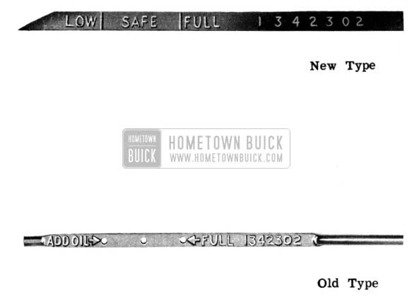
Beginning approximately August 31, 1950, some engines will appear with a new type crankcase oil gage rod made from .062 flat stock, rather than the .156 round stock used at present. (See Figure 1)
1950 Buick Crankcase Oil Gage Rod
The new rod will provide a more readable oil level and also greater flexibility which should reduce bending and breakage in service.
For the present, it is intended that the new flat rod be used optionally with the round rod. Both will be designated as Group 1.516, Part No. 1342302, Rod, Crankcase Oil Gage.
We have had a few reports to the effect that some dealers are tightening manifold bolts and nuts as a matter of routine during new car make ready and the 1,000 and 2,000 mile inspections. Other dealers are tightening these bolts and nuts in a haphazard manner in an attempt to correct exhaust leaks. In either case, it appears that no definite tightening procedure is used, with the result that we are receiving excessive com plaints of broken or warped manifolds.
When working on intake and exhaust manifolds it must be understood that both manifolds must be attached to the valve body and to the cylinder head in such manner that slippage can take place at the joints to compensate for differences in rate of expansion and contraction of the several parts due to heat. This is necessary because the parts do not have the same temperature under all operating conditions.
The assembly and method of attachment of these parts have been designed to avoid leakage of joints while permitting the required slippage. If attaching bolts and nuts are not tightened in proper sequence or are tightened excessively, warpage, leaking joints or cracked manifolds will result.
When leakage occurs at manifold joint the condition can usually be corrected by proper adjustment of bolts and stud nuts without removing or replacing parts. Do not attempt correction by simply tightening bolts or nuts at point of leakage. Instead, loosen all manifold to valve body and cylinder head bolts and nuts, allow parts to cool to shop temperature, then tighten bolts and nuts to specified torque in the sequence given in step 5 below.
The following assembly and installation procedure for 1950 Buick Engine Maintenance should be used when replacing either manifold or the valve body. Manifolds should never be removed while engine is hot because warpage is liable to occur.
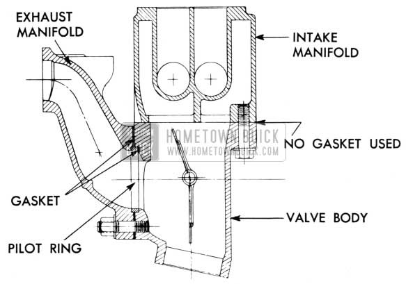
- Install the valve body on the exhaust manifold with a new ring gasket in pilot ring recess in body and a new gasket between body and manifold; make sure that pilot ring is in place. See Figure 2. Leave attaching stud nuts snug but not tight.
1950 Buick Intake Manifold
- Tighten manifold to cylinder head stud nuts to 25-30 ft. lbs. torque.
- Tighten exhaust manifold to valve body stud nuts to 25-30 ft. lbs. torque.
- Tighten intake manifold to valve body bolts to 15-20 ft. lbs. torque.
It has been brought to our attention that a typesetting error appears in the 1950 Shop Manual, Section 2-E, Paragraph 2-21b (7), Page 2-30, relating to bearing clearance. The text states that a new bearing installation is advisable if the clearance exceeds .022”. Obviously, this figure should be .002”. Please make the necessary correction.
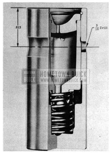
Approximately August 21st, 1950, the design of hydraulic valve lifter assemblies used in production was changed as shown in Figure 3.
1950 Buick Hydraulic Valve Lifters
New and old lifters are interchangeable and it is felt that addition of the groove and hole in the lifter body will provide increased oil flow through the lifters.
SERIES *EFFECTIVE ENGINE NOS,.
40 Dyn. 6068278 Continuous
50 SM 6053001 – 6053599 Incl.
6063100 – 6068099 Incl.
6068276 Continuous
50 Dyn. 6053003 – 6053599 Incl.
6063100 – 6068099 Incl.
6068276 (Except 6071158 – 6071213 Incl.) Continuous
50 RE 157421 Continuous
70 Dyn. 6053004 – 6053599 Incl.
6063100 – 6068099 Incl.
6068276 Continuous
70 RE 511651 Continuous
*The engine number suffix “4”, “5”, or “7” is added to the above numbers, according to Series designation.
Approximately March 15th, 1950, valve push rods used in Series 40 engines with .015″ lash valve systems will have a redesigned upper end.

1950 Buick Valve Push Rods
As shown in Figure 4, the push rod upper end, which can be identified by a copper color finish, has been decreased in overall height. The ball stud recess, however, has been increased in depth to provide a shroud effect and prevent oil from spraying over the valve stems. In addition, the oil passage formerly drilled at the bottom of the ball stud recess has been eliminated thus preventing oil fed to the ball studs from draining through the push rod stems into the crankcase.
The push rod stem and lower end remain the same as those used on Series 40 hydraulic lifter engines except that the small bleed hole, formerly located in the side of the stem under the upper end shroud, has been eliminated.
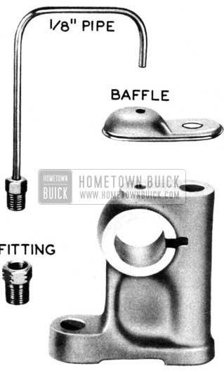
Due to elimination of the oil passage in the ball stud recess, it is necessary to provide a means of reducing excessive oil pressure in the rocker arm shaft. This is accomplished by reducing the rocker arm shaft oil inlet pipe from 3/16″ to 1/8″ diameter, and using an oil baffle on the front rocker arm shaft bracket. The 1/8” pipe fits loosely in the bracket oil hole and relieves excess pressure in the shaft by allowing oil to bleed around the pipe, against the baffle, and downward over the cylinder head. In conjunction with the new oil pipe, the restricted fitting in the cylinder head has been redesigned and can be identified by two notches in the hex section of the fitting. An exploded view of the new assembly is shown in Figure 5.
1950 Buick Hydraulic Lifters Cylinder Assembly
Part numbers of new assemblies follow. Note that the valve push rod will not be furnished as a separate part.
Group Part No. Description
0.426 1390515 Kit, Valve Push Rod, Adjusting Stud and Nut
0.354 1342582 Baffle, VRA Shaft Oil Inlet Pipe
1.740 1342578 Fitting, VRA Shaft Oil Inlet Pipe to Head
1.917 1342577 Assembly, VRA Shaft OU Inlet Pipe
Occasionally we receive reports from the field that dowel pin holes in service crankshafts, for Dynaflow jobs, are oversize. This matter was covered in the 1949 Abridged BPS Edition, page 22, under the subject “Dynaflow Crankshaft Replacement,” and again in the Revised Dynaflow Shop Manual, Section 6, Paragraph 30 (c), page 63.
Please arrange to have service personnel familiarize themselves with this procedure of 1950 Buick Engine Maintenance.
When the water pump boss on the Upper Cylinder Crankcase, Part No. 1338163, was lowered, no clearance was allowed for the flanged edge of the Front Engine Support, Part No. 1323887, for 1940 – 1948 Service jobs. This same condition applies to replacement engine, Part No. 1390168, and also Service Crankcase requiring Front Engine Supports, Part Nos. 1304258, 1303247 or 1308626 for use respectively on 1937, 1938 and 1939 cars. To permit clearance in each of the above cases, it will be necessary to remove the affected portion of the support as illustrated in Figure 6.
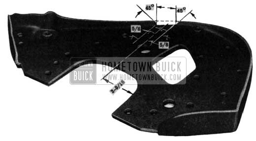
1950 Buick Engine Support-Front
It has been brought to our attention that some dealers are not using a tapered sleeve ring compressor as specified in Paragraph 2-23 (subpar. f, Step 6) of the 1948-1949 Buick Shop Manual.
May we again stress the importance of using a ring compressor of this type for the installation of piston and rod assemblies when the piston is equipped with flex-fit oil rings.
The effectiveness of this type piston ring is decreased when the “U ” segments are bent and do not come in contact with the cylinder wall. To overcome this difficulty, the following size tapered sleeve ring compressor should be used. These will properly compress standard and all authorized over-size rings.
Series 40 Engine – 3-3/32″
Series 50 Engine – 3-3/16″
Series 70 Engine – 3-7/16″
An approved tapered sleeve ring compressor may be purchased from one of the following companies or their jobbers:
Cal-Van Machine Products, Inc. – Jackson, Michigan
Cornwell Quality Tools Co. – Mogadore, Ohio
Herbrand Div. of Bingham, Herbrand Corp. – Fremont, Ohio
Kent-Moore Organization, Inc. – Detroit, Michigan
Snap-On Tools Corporation – Kenosha, Wisconsin
Leave A Comment
You must be logged in to post a comment.