The most satisfactory method of preventing a paint “scrubbing” condition between the hood and front fenders on 1949 Series 50 and 70 cars is to install 1950 type hood guides and spacers. This installation will also simplify hood alignment because it automatically spaces the split line between the hood and fenders.
Installation is made as follows:
- Remove the rectangular hood bumper located just to the rear of the front hood hinge.
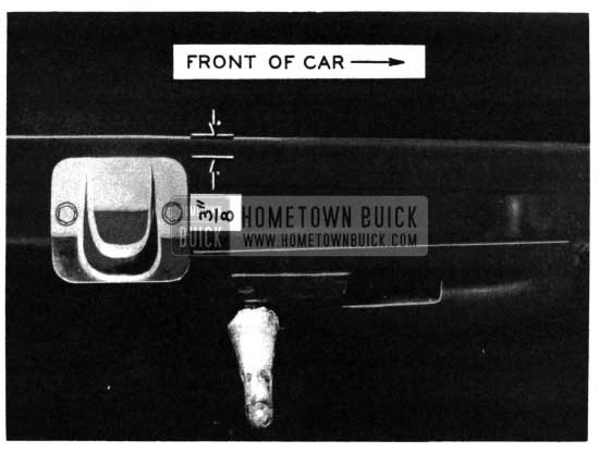
- Center a hood spacer guide, Group 8.037, Part No. 1342263in the space formerly occupied by the hood bumper, with the top of the guide just below the top of the fender (similar to installation on 1950 cars) and scribe the mounting hole locations. (See Figure 40.)
1950 Buick Hood Spacers
- Drill at center of scribed holes, using a #28 (.140) or #29 (.136) diameter drill.
- Install the guide using #8-18×1/2 Type “B” (187875) self-tapping screws or equivalent. (It may be necessary to bend the guide slightly to provide a tight fit against the fender flange.)
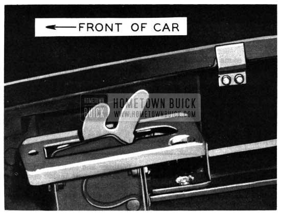
- Lower the hood and scribe a light chalk mark at the split line to correspond with the center line of the guide installed in Step #4.
- Using the chalk line as a center line, place a hood spacer Group 8.031, Part No. 1341537, in the position shown in Figure 41.
1950 Buick Hood Spacers Installation
- Using same drill listed above, drill at center of scribed holes and install the spacer with same type and size self-tapping screws used in Step No. 4. (The slotted spacer mounting holes will provide any necessary vertical adjustment.)
When correctly installed, the guides and spacers will require a slight pressure to fully close the hood and will serve to hold the hood in correct alignment when closed.
AFA’s will not be accepted for installation of these parts.
Approximately March 15th, the hood fastener and hinge assembly on all Series 1950 jobs will be changed in production to an inside opening type. Although the new mechanism is similar to that used on 1949 models, several improvements have been made, particularly in the method of adjusting the hinges. The adjustment procedure also differs from that used with 1st type 1950 assemblies having the outside handle opening feature.
With 1st Type 1950 hinges it is necessary to make both “fore and aft” (horizontal) and “up and down” (vertical) adjustment at the point where the hinge bolts to the fender rail. The new hinge provides two separate points of adjustment; vertical at the point here the hinge assembly bolts to the fastener mechanism, and horizontal at the point where the hinge bolts to the fender rail. With this arrangement it is not necessary to disturb the pivot point (when correctly set) in order to make any necessary vertical adjustment.
Use of the new hinge and fastener assembly also involved redesigning of the fender rails, fender skirts and hood. As a result, it will be necessary, to assign 1st and 2nd Type part numbers to the skirt and hood assemblies, as follows:
1st Type 2nd Type
Group Part No. Part No. Item
1338258 1342498 Assy-Hood – 40 – 50
8.000 1339882 1342499 Assy-Hood – 70
8,153 1340056 1342520 Assy-Frt. Fndr. Skirt- Right –All
8.153 1340057 1342521 Assy-Frt. Fndr. Skirt- Left – AllDue to the fact that 1st and 2nd type fender rails are easily made inter changeable for use with either type hinge and fastener assembly, fender part numbers will not be changed.
In the event that it becomes necessary to install a 1st type front fender on a car equipped with the 2nd type hood mechanism, or a 2nd type fender on a car equipped with the 1st type hood mechanism, minor reworking of the fender rails will be necessary. These operations are shown in Figures 42 and 43.
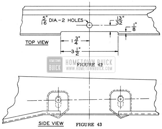
1950 Buick Fender Works for Hood Mechanism
- 1st Type Fender -2nd Type Hinge
- Cut away the fender rail, at each hinge location 9 to the dimensions shown in Figure 42.
- Drill a 5/16″ diameter hole at each hinge centerline location (Figure 42) and install rubber bumpers, Group 8.037, Part No. 503865, one per hole.
- Bolt the hinges in position at the top of the slotted holes in the fender rails.
- 2nd Type Fender – 1st Type Hinge
- Because vertical hinge adjustment is not made at the fender rail with 2nd type fenders do not have slotted hinge bracket mounting holes. When using 1st type hinges with 2nd type fenders, it may be necessary to elongate the round mounting holes as shown in Figure 43, in order to provide sufficient vertical adjustment. The solid circle shows the original mounting holes and the dotted lines show how they should be elongated, if additional vertical adjustment is found to be necessary.
It will be possible for service to use the 2nd type fender skirts with the 1st type hinges. It is not possible, however, to use 1st type fender skirts with 2nd type hinges.
Leave A Comment
You must be logged in to post a comment.