Effective approximately February 15th, the 1950 Buick Carburetor (Stromberg) will have a redesigned main body, in which the fuel level will be at the bottom of the inspection hole threads. This change was made because of the difficulty in accurately checking fuel level with the first type carburetors.
 Main Body Change")
1950 Buick Carburetor (Stromberg) Main Body Change
As illustrated in Figure 7, the new type 1950 Buick carburetor can be readily identified by the boss at the inspection hole. This boss is increased in diameter and is flanked by two horizontal ribs approximately 1/4″ long and 1/16″ wide. In addition, the inspection hole is lowered so that it is not located in the exact center of the boss.
All specifications and adjustments, with the exception of the fuel level, remain the same as specified for the first type 1950 Buick carburetor.
The same procedure may be used for setting the earlier vacuum type and the later atmospheric type dash pots on Dynaflow cars. A. different procedure has previously been given for each type. The following procedure supersedes all previous instructions on adjustment of Dynaflow throttle linkage and dash pot.
- With engine HOT and idling at 450 RPM, check clearance between the stop on lever at lower end of equalizer shaft and the shaft lower bracket. See Figure 8.
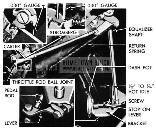
1950 Buick Throttle Rod Ball Joint
If clearance is not 1/32 ” to 1/16″, adjust throttle operating rod at ball joint to obtain 1/32″ to 1/16″ clearance. Tighten lock nut.
A change has recently been made in Stromberg Carburetors for 1950 Buicks, Part Nos. 1339690 and 1339692, to eliminate trouble caused by the starter switch slide sticking in the housing.
A new stamped pump arm is used in connection with a new starter switch assembly that has a stronger contact spring made of .026″ diameter wire. Older type springs were .024″ diameter. These improvements also necessitated a new pump rod and arm assistor spring to maintain proper closing of the throttle (See Figure 9).
 Starter Switch")
1950 Buick Carburetor (Stromberg) Starter Switch
The new switch will be identified by a letter “A” stamped on the side of the housing as shown in Figure 10.
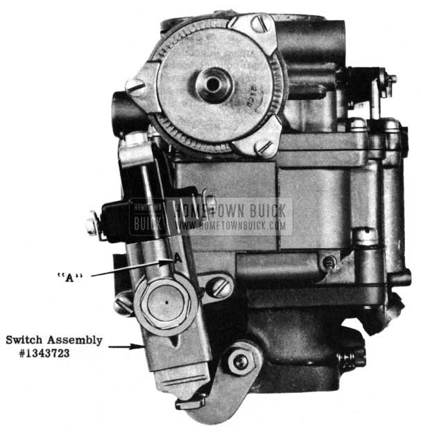
1950 Buick Stromberg Carburetor Starter Switch Assembly
We wish to emphasize that this switch is only adaptable to 1950 Buick carburetors having the new stamped pump arm and assistor spring. Under no circumstances should it be assembled on 1950 Buick carburetors not having these features.
New parts are follows:
Group Part No. Description
3.541 1343723 Starter Switch Assembly
3.779 1343726 Contact Spring
3.780 1343510 Pump Arm
3.780 1343724 Arm Assistor Spring
3.782 1343725 Pump Rod
We are receiving many complaints that trouble is experienced with choke operation when attempting to restart a car that has been driven a short distance. A good share of this trouble has been traced to faulty adjustment of the choke unloader. We strongly recommend that the unloader linkage be checked and adjusted, if necessary, when the new car inspection is made. Along this same line, customers should be advised that if the engine becomes flooded, easier starting will result if the accelerator pedal is depressed all the way to the toe board.
In the near future some 1950 jobs will appear with 1950 Buick Carter carburetors designated as 725SA on 40-50 cars and 726SA on 70 jobs.
This change involves relocation of the bowl vents to the rear side of the air horn in order to eliminate gasoline odors when the car is in motion. In the event that it is desirable to relocate the vents on 1950 Buick Carter Carburetors in service, it will be necessary to install the new type air horn and air horn gasket. In addition two holes must be drilled in the bowl cover to coincide with the location of the vents on the new air horn. This can be done by placing a new type air horn gasket on the bowl cover and scribing the location of the vent holes, in the gasket, on the cover. Drill with a 1/4″ drill. The location of these holes is not particularly critical, but they should be held within reasonable limits.
Group Part No. Description
3.742 1344077 (70)
1344079 (40-50) Bowl Cover
3.774 1344075 Air Horn and Climatic Control
3.774 1344076 *Air Horn and Piston Housing
3.777 1344078 *Air Horn Gasket
*Parts required to convert first type.
Instructions given in the 1948-49 Shop Manual, paragraph 3-33 (a), item 6, for installing reducer wires in 1950 Buick Stromberg carburetors are incorrect. This paragraph should read: Place new gasket on main body. Insert short ends of reducer wires in idle channels in throttle body, and guide long ends of wires into idle channels in main body as bodies are assembled together. Install screws with lock washers.
Kindly make the necessary correction in the shop manual.
We have been notified by the Parts Department that they will no longer service vacuum type dash pots for 1948-70, 1949-50-70 and 1950-40 first job Dynaflows. In view of this, it will be necessary to use an atmospheric type pot when making replacement on the above jobs.
A special service dash pot will be available for 1948 and 1949 jobs, making it unnecessary to use a longer adjusting screw to compensate for plunger length. The regular 1950 production pot should be used on first type 1950 Series- 40 cars. Parts information is as follows:
Group Part No. Replaces Model
3.440 1342739 1336677 1948-49-70
1949-50
” 1341752 1341220 1950-40
1st jobs
Use the following procedure when making installation:
- Remove old dashpot and pot-to-manifold vacuum tube and hose.
- Remove vacuum booster line at manifold, replace “T” fitting on manifold with Group No. 8.963, Part No. 137405, 1/4″ Connector, and replace booster to manifold line.
- Install atmospheric type dash pot as specified for Model.
- Set engine idle at 450 RPM – Hot.
- Follow complete throttle linkage and dash pot adjustment as outlined in the 19’50 Buick Shop Manual, Section 3-c, paragraph 3-8 (b), page 3-11.
All 1950 models are now equipped in production with a Moraine Products gasoline filter of entirely new design. The new filter utilizes a porous bronze filtering disc which is an integral part of the filter and cannot be replaced in service.
A drain plug is provided at the bottom of the inlet side which allows water and other accumulation to be easily removed. When a thorough cleaning is desired, the filter should be removed, swished-around in a suitable solvent and blown-out with an air hose in the outlet side. Make sure that the drain plug is removed before blowing air through the filter.
A short time ago, the 1950 Buick carburetor made by Stromberg were equipped with a Pump Arm Assistor Spring, Part No.1343547, Group No.3.780, designed to provide more positive throttle closing. In case where the throttle will not return to proper idle position, it is advisable to equip earlier jobs in the field with this assistor spring.
Leave A Comment
You must be logged in to post a comment.