GRILLE FRAME BOLTS
1955 MODELS
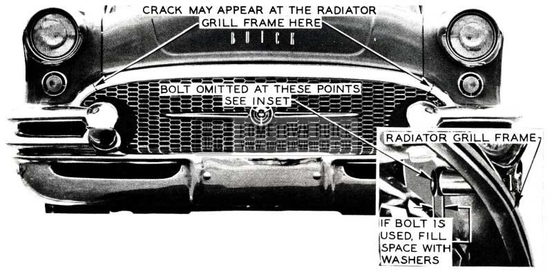
Two bolts, which attach the radiator grille frame to the fender sheet metal, have been intentionally omitted on some production jobs; therefore, it will not be necessary to install these bolts •in the field. (See Figure 38).
1955 Buick Grill Frame Bolts
If bolts were installed at the factory, care should be used whenever tightening is attempted as cracking or distortion of grille frame could result.
If, for any reason, bolts at these points are installed in the field, washers should be used to fill the space between the grille frame and fender to eliminate any undue strain on the grille frame, while tightening. (This space can be viewed from under the grille frame at the points indicated in Figure 38.
FRONT END SEALING
FRONT FENDER SEALING – 1955 MODELS
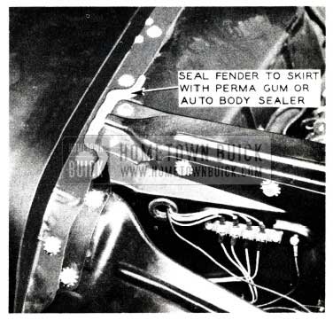
To prevent the possibility of water and chloride from running down over the electrical connections at the head lamp junction block, it is recommended that Perma Gum or 3M heavy auto body sealer be used to seal both front fenders to skirt around radiator shell support as shown in Figure 39.
1955 Buick Front End Sealing
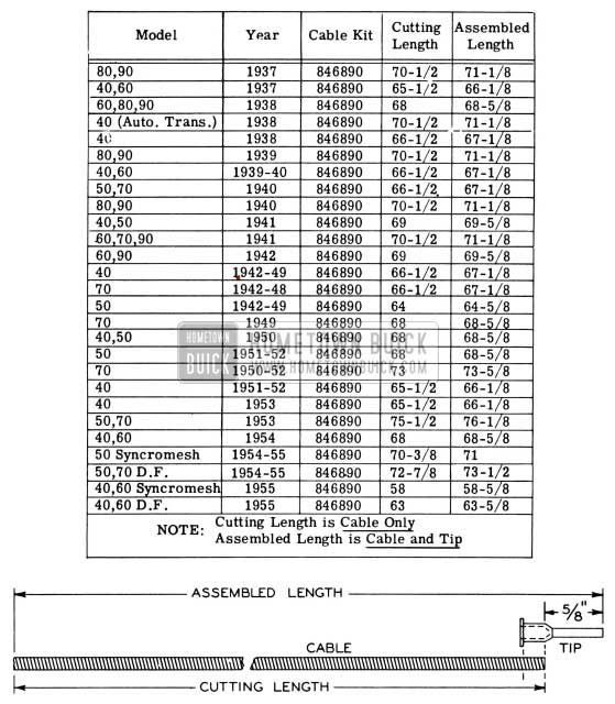
A Speedometer Cable length chart showing lengths to which the Group No. 4.342, Part 846890 Cable must be cut corresponding with the particular year and model car is shown in Figure 40. This chart includes all models from 1937 thru 1955. A diagram showing cutting length as related to assembled length is also included to further simplify the cutting instructions.
BUICK SPEEDOMETER CABLE LENGTH CHART
1955 Buick Speedometer Cable Length Chart
FOR USE IN DETERMINING CUTTING LENGTH OF 846890 CABLE
Buick Speedometer Cables are made of the highest grade steel wires on special, patented winding machines.
Buick Speedometer Cables are heat-treated by patented methods to assure highest possible quality, which means:
- Quiet, steady performance of flexible shaft and speedometer.
- Smooth and free running around bends.
- Steady driving torque of long flexible shaft; hence, steady pointer performance of speedometer.
- High torque strength gives long life.
SPEEDO CABLE CORRECTION
1955 SERIES 50-70
Several reports have been received of speedometer noise, fluctuating reading, and cable breakage. The following information will assist in correcting this condition:
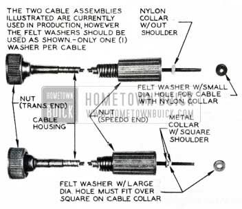
- At present there are two types of speedo cables being used in production. One cable has a metal collar which acts as a stop when inserting the cable and into the speedo head; (2) the other has a nylon collar for the same purpose.
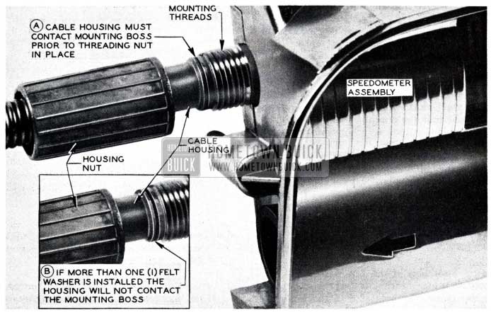
- During assembly, a felt washer is positioned between the cable stop (collar) and the speedometer head. There are two (2) types of felt washers currently in use. One washer has a small hole which is for use on the cable with the nylon collar. The other washer has a larger hole for use on the cable with a metal collar. See Figure 41.
1955 Buick Speedo Cable Correction
Summary:
- Two (2) types of speedo cables currently in use. (Nylon collar – steel collar) See Figure 41.
- Two (2) types of felt washers currently in use (identified by diameter of hole in washer).
- Felt washer with small hole used on speedo cable with nylon collar.
- Felt washer with large hole used on speedo cable with steel collar.
- Only One (1) felt washer used between speedo head and cable collar. See Figure 42.
1955 Buick Speedometer Assembly
Illustrations:
- Two types of cables – Label -Metal and Nylon Stop. See Figure 2.
- Two washers show large and small hole, and which washer is used with their respective cables. See Figure 41.
- Proper assembly (exploded view or cut away j Show position of felt washer and make note that only one is used. See Figure 42.
NOTE: If the source of trouble of a complaint has been traced to the felt washers as described, it is recommended that the cable be replaced during service operations.
TWO PIECE RADIATOR GRILLE FRAME
1955 – 40 Series
Some early 1955-40 Series cars are equipped with two pieces inner radiator grille frames. If for any reason it is necessary to replace only one section of the frame, (right or left), a complete new one-piece frame , Gr. 1.267, Part # 1166506 will have to be installed. The two pieces frame that makes up the inner grille bar on some 40 Series will not be made available for service as there are only a few cars so equipped.
WHEEL ALIGNMENT TOE-IN CHANGE
1955 Model
We have been advised by our Engineering Department that “Toe-In” specification on all 1955 models, has been changed from “0-1/16″ to ”1/16 – 1/8” to improve car handling. It is suggested that dealer service men responsible for checking front end alignment make this correction on their charts and in the 1955 Shop Manual in Page 7-22, Fig. 7-16.
BALANCING REAR WHEELS
When balancing rear wheels with an “on the ear” balancer reasonable wheel speeds must be used to eliminate possible damage to rear axle parts. Manufacturers of this type equipment recommend that the rear wheel speed be held below forty miles per hour as registered on the speedometer when balancing. When balancing one rear wheel with this type equipment, the wheel is spinning approximately twice the speed as that indicated on the speedometer, because the other wheel is held stationary. For example, if one rear wheel is held and the other rotated at a speed of 40 miles per hour as registered on the speedometer, the wheel will actually be traveling at a speed of approximately 80 miles per hour.
The manufacturers’ recommendation of never exceeding a speedometer reading of 40 miles per hour is based on the fact that rear wheel unbalance is most noticeable at speeds between 30 to 40 miles per hour and 60 to 70 miles per hour and any speed beyond this is unnecessary.
Therefore, when balancing rear wheels on the car, the most noticeable unbalance condition will be felt or recorded before the speedometer reaches a speed of 40 miles per hour.
TIRE COMPLAINTS
1955 Tubeless Tires
We have received a few reports whereby difficulty has been encountered in balancing tubeless tires due to loose rubber balancing material being in the tires.
In these instances it is suggested that the car be taken to the tire dealer handling that particular make of tire. Dealers of various tire manufacturers supplying Buick have been notified of their responsibility and obligation regarding this matter; therefore, if any difficulty is encountered by dealers in obtaining service, we would like you to notify your local zone office so that it may be brought to the attention of the proper people.
LOWER CONTROL ARM PIN CHANGE
1955 Model
A change has recently been made in the assembly of the lower control arm outer pivot pin and bushing.
The head of the bushing was reversed so that it will be to the front of the car on the right hand side and to the rear on the left handside. This was done so more accurate assembly could be made. It was also decided to line up the pivot pin head and grease fitting in the same manner. The pivot pin can be assembled either way as the function of this part is not impaired by the rev1sal of the pin and bushing.
SPEEDO CABLE BREAKING
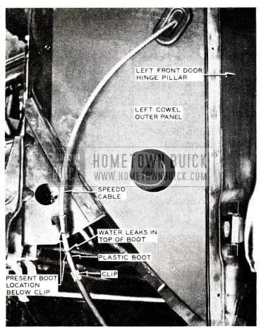
A few cases have been reported that speedo cables are breaking due to water leaking in the top of the plastic boot around the cable. See Figure 43.
1955 Buick Speedometer Cable Braking
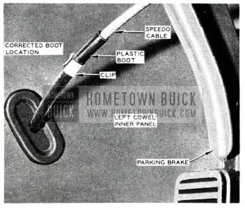
To correct th1s condition, open the clip holding the boot (Figure 44) and slide the plastic boot up to about 16″ from the speedo head, or on the inside of the cowl trim pad as shown in Figure 44. Then fasten clip in position with a pair of pliers.
1955 Buick Speedometer Cable Correction
Correction has been made in production by installing a longer boot.
REPAIRING HOLES IN WHEEL RIMS
1954-55 Models
We have received a few requests for information on the proper method of repairing small air leaks in chassis wheels.
Our Engineering Department advises that ”Seal-All”, a product of Allen Products Corporation, Detroit, Michigan, is a good sealing material to use for this type repair. This material should be purchased in tubes for easy application, maintenance of proper consistency, cleanliness and for minimizing fire hazards due to the volatility and in flammability of this material.
The following method is applicable for defects in wheels which do not exceed 1/64” width and 1/8″ length. Wheels having defects larger than this should be replaced.
- Sealant may be applied over painted areas providing surface is clean and dry. Clean defected area by saturating a cloth with paint solvent, carbon tetrachloride, tri-color ethylene or other grease solvent and gently wipe the leakage area.
CAUTION: This should be done at room temperature in well ventilated room.
- Sealant should be applied moderately heavy (directly from the tube) to the tire side of the rim only.
- Allow to dry for two hours before installing tire.
NOTE: The above instructions apply to riveted as well as welded wheels.
WIRE WHEEL CARE
Numerous requests have been received regarding the care of wire wheels and asking what is the life expectancy of a wire wheel. There is no way of determining the life of a wire wheel, because the driving habits of an individual as well as road conditions play a great part in determining this. Our Engineering Department recommends that the wheels be checked whenever an owner has new tires installed. It is not recommended that the dealer servicemen attempt torquing the spokes because any slight over torquing will greatly affect radical and lateral run out. We are, therefore, listing the Kelsey Hays service stations to which wire wheels may be sent for checking.
Auto Wheel & Rim Service
900 South 7th Street
Louisville 3, Kentucky
Auto Wheel Service
N. W. 10th & Flanders
Portland 9, Oregon
Auto Wheels & Supplies Ltd.
4690 Iberville
Montreal 34, Quebec
Bearing & Rim Supply
1202 Second
Spokane 8, Washington
Borbein-Young & Company
3663 Forest Park
St. Louis 8, Missouri
Colbourn Wheel & Rim Co.
214 N. Franklin
Syracuse 4, New York
Dixie Wheel Company
916 N. Boulevard
Richmond 20, Virginia
Frey, The Wheelman, Inc.
520 Ellicott
Buffalo 3, New York
Frey, The Wheelman, Inc.
110 Savannah
Rochester 7, New York
Henderson Rim & Wheel Service
32 E. 5th South
Salt Lake City 1, Utah
Illinois Wheel & Brake Co.
1111 East Washington
Springfield, Illinois
Indiana Wheel & Rim Co.
1340 North Senate
Indianapolis 2, Indiana
Kay Wheel Sales Company
38th & Powelton
Philadelphia 4, Pennsylvania
Motor Rim & Wheel Service
2860 East Pico Boulevard
Los Angeles 23, California
Motor Rim & Wheel Service
3075 – 17th St. at Folsom
San Francisco 10, California
Motor Rim Manufacturers
153 Wooster
Akron 7, Ohio
W. Norris & Sons Inc.
Gay & High Streets
Baltimore 3, Maryland
Pioneer Rim & Wheel Co.
28th & West Front
Fargo, North Dakota
Pioneer Rim & Wheel Co.
1220 Marquette
Minneapolis 4, Minnesota
Quinn & McGill Motor Supply
437 Broadway
Denver 1, Colorado
Rim & Wheel Service
1014 Gest Street
Cincinnati 3, Ohio
Rim & Wheel Service
5132 Third Avenue
Detroit 2, Michigan
Southeast Wheel & Rim Co.
927 W. Forsyth
Jacksonville 3, Florida
Southern Wheel & Rim Co.
1028 Dryades
New Orleans 13, La.
Southwest Wheel Inc.
944 South Lamar
Dallas 2, Texas
Southwest Wheel Inc.
2120 McKinney
Houston 2, Texas
Southwest Wheel Inc.
1501 East Broadway
Lubbock, Texas
Southwest Wheel Inc.
1300 S. Alamo at Guenther
San Antonio, Texas
Southwest Wheel Inc.
814 W. Grand
Oklahoma City 1, Okla.
Standard Wheel & Rim
200 South Cameron
Harrisburg, Pennsylvania
Stone Wheel Incorporated
2540 South Wabash
Chicago 16, Illinois
Wheel & Rim Co. of Canada
38 Yarkville
Toronto 5, Ontario
Wheel, Rim & Parts Company
2021 Fifth Avenue, South
Birmingham, Alabama
Wheels & Brakes Inc.
1600 N. Second
Albuquerque, N.M.
Wheels Incorporated
222 West 65th Street
New York 23, New York
STABILIZER BAR INTERFERENCE
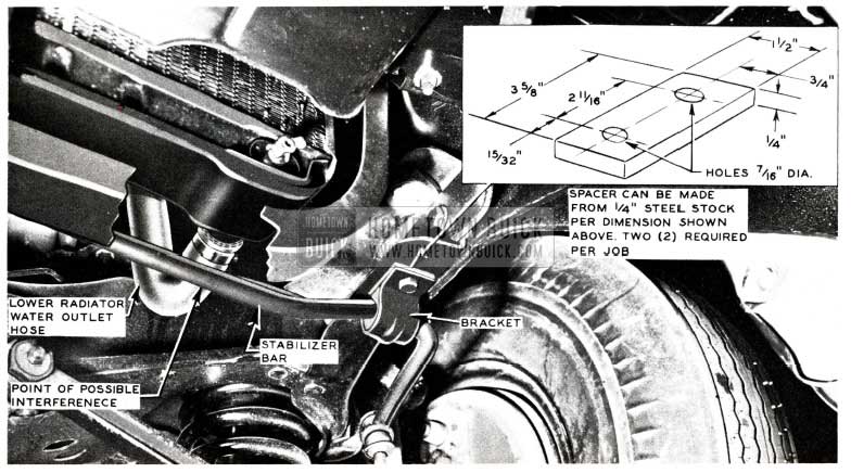
It has been reported that on some 1955 cars, the water outlet hose and the stabilizer Bar have been making contact. It is suggested that a minimum clearance of 3/16 of an inch be maintained at this point. Whenever this condition is encountered, it is recommended that a spacer be used between the stabilizer bracket and the chassis as shown in Figure 45. When using the spacer it is necessary to use longer mounting bolts in order to permit proper assembly.
1955 Buick Stabilizer Bar
TIRE THUMP
Tire thump has developed into a sizable problem for dealers to handle. In recent years the problem has paralleled the progress made by car manufacturers in reducing noise level of car operation.
Tire thump is caused from minor tire or wheel construction irregularities, which is felt or heard between 15-25 MPH and has not as yet been entirely eliminated. Until that time it will take the full cooperation of the dealer and tire manufacturers organization to effectively handle each individual tire claim as they are presented by the new car owner.
Thump and vibration complaints can be substantially reduced through a better understanding of the problem, and by assuring the owner that tire thump will in no way cause or contribute to tire failure. It does not affect the structural integrity of the tire nor will it reduce the amount of service the customer would normally receive from it.
The best approach to any complaint of this type is to find out the extent to which it is objectionable. When checking tire thump complaints, insist that the owner of the car ride with you. If it is necessary to accelerate or decelerate through a critical speed range to bring out the condition, or if the owner claims the disturbance is noticeable only on certain days or when peculiar weather conditions exist, or while driving on specific sections of a road, switching tires may reduce thump condition to which an owner will accept it, but it will not eliminate it nor will changing the tires correct it.
It is easier and more economical if slight disturbances are explained to the customer as normal conditions rather than making a replacement and then learning that he is still not satisfied.
If the condition is found to be severe enough to become a real annoyance to the owner and he is not content to accept the disturbance as a normal condition, the following steps are suggested:
Inspect the Tires.
Always notice whether the tires are nylon (deluxe type) or regular production. If they are nylon, be sure the car has been driven far enough, (approximately 5 or 6 miles) to remove any “set” which is characteristic of nylon, tires regardless of brand or type.
Make sure the tire is not cut or ruptured and no foreign material is in the tread groove and that the beads are seated properly.
Identify the Offending Tire.
Inflate all tires to 50 lb. pressure and drive over smooth surfaced road. If the increased inflation does not eliminate the condition, it probably is not tire thump. Road shock is sometimes mistakenly identified as thump. If the higher inflation does eliminate the condition, decrease the air pressure in one tire to the recommended inflation and repeat the road test. Repeat this procedure until the tire or tires with objectionable thump have been isolated. If a tire is found to have objectionable thump at recommended pressure, it can be assured the tire is at fault.
After isolating the offending tire, cross-switch the tire and wheel, to reverse the direction of rotation, and road test the car again to see if the objectionable thump has been reduced or eliminated. If the objectionable disturbance is still experienced, replace the offending tire.
SOME FACTS TO BE REMEMBERED ABOUT TIRE THUMP:
- Tires which thump on one automobile will not necessarily thump on another of the same make and model.
- The thump level varies with the position of the observer in the car. It may be apparent in one seat and none-existent in other seats in the same car and to the same person.
- It will not cause or contribute to any tire failure, or reduce the amount of service the customer would normally receive from his tires.
- It is not confined to any one brand or type of tire or to any one make or model of car.
HOOD SAFETY HOOK
A few cases have been reported of hoods flying open on early 1955 models. The source of trouble has been traced to the safety hook hanging up on the sheet metal flange of the hood, as the safety hook is pulled forward. During release of the hood on early models, it is possible for the hook to “hang up” as indicated in Figure 46.
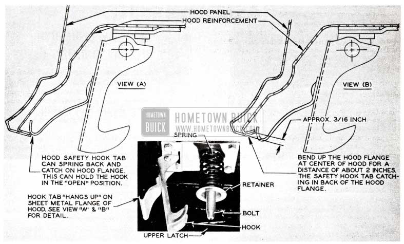
1955 Buick Hood Safety Hook
View (A) preventing the hook from returning to its normal positon after the hood is closed.
To eliminate this condition, it is necessary to bend the hood flange slight upward as shown in Figure 4b. View (B).
WHEEL COVER RATTLES
1955 70 SERIES
It has been reported that the Buick medallion in the center of the Roadmaster wheel cover works loose causing a rattle. This can be corrected by replacing the flat type clip shown in View A, Figure 46 with the new “U” shape clip, Group No. 5.859, Part No. 1169090 shown in View B, Figure 47.
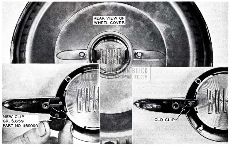
1955 Buick Wheel Cover Rattle Correction
Leave A Comment
You must be logged in to post a comment.