ENGINE GENERAL SPECIFICATIONS
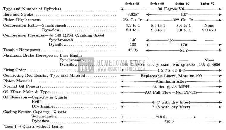
1955 Buick Engine Specifications
Except for changes described in this group, the 1955 model engines remain the same as the 1954 for all series.
2-1 COMPRESSION RATIO
Series 40 Engines
The Synchromesh engine has a compression ratio of 7.5 to 1, and the Dynaflow engine has a compression ratio of 8.4 to 1. As in 1954, the differences in ratios of the Synchromesh and Dynaflow engines are obtained by the use of pistons with different dome heights.
Series 60-50-70 Engines
The Synchromesh engines used in Series 60-50, have a compression ratio of 8.4 to 1, with steelbestos gaskets .045″ thick. The Dynaflow engine, Series 60-50-70, has a compression ratio of 9.0 to 1 with steel gaskets .015″ thick. A comparison of 1954 and 1955 compression ratios is shown in figure 2-1.
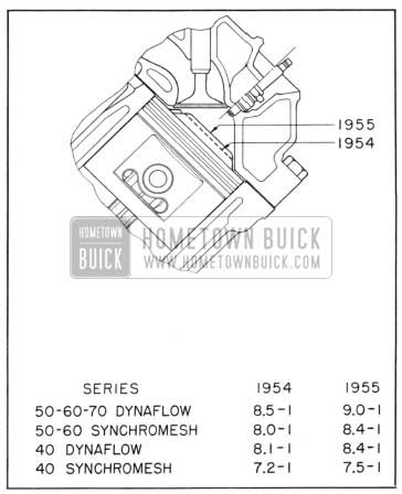
1955 Buick 1954 and 1955 Compression Ratios
2-2 CRANKSHAFT AND BEARINGS
A heavier main bearing cap is used on all series for 1955. The new bearing cap, shown in figure 2-2, will add support to the crankshaft.
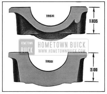
1955 Buick Main Bearing Cap
2-3 CONNECTING RODS AND PISTONS
Moraine 400 aluminum alloy bearings are used for all connecting rods for 1955. The new bearing is comprised of a steel backing to which is clad approximately .010″ cadmium, silicon, aluminum and high-lead babbitt. The new materials are better suited to meet the requirements of connecting rod bearings.
The 1955 piston has an additional slot below each wrist pin boss. See figure 2-3.
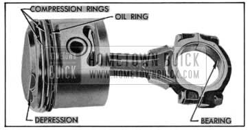
1955 Buick Connecting Rod and Piston Assembly
This slot relieves the piston from any load or heat distortion of the wrist pin boss and insures that the bottom of the piston will retain its shape under all operating conditions.
The piston dome height has been increased slightly, which accounts for the increase in compression ratios previously covered.
2-4 CYLINDER HEADS
The cylinder heads remain the same in all series except for changes in the exhaust valve seat and exhaust ports and passages.
The exhaust valve seat has been increased in size to accommodate the larger exhaust valve. Exhaust ports have been further streamlined to accommodate the increased flow of gases from the larger valve. The two exhaust passages in each head, leading to the intake manifold, have been redesigned reducing manifold heat with the heat control valve open.
2-5 VALVES AND CAMSHAFT
The intake valves for both Buick engines re main unchanged for 1955, however the exhaust valves have been increased in diameter to 1 3/8.
The camshaft for the 1955 Series 40 engine remains the same as that used in 1954.
The camshaft for the 322 cubic inch engine, used with the Dynaflow transmission, has an increased exhaust cam lift resulting in a valve lift change from .350″. to .378″. The valve timing has been modified for this engine, whereby the intake valve opens 3 degrees earlier and closes 2 degrees later, and the exhaust valve opens 5 degrees earlier and closes at the same time as the 1954 valve.
The camshaft for the 322 cubic inch engine, used with the Synchromesh transmission, is the same as 1954 and should not be interchanged with the Dynaflow camshaft, as rough idle will result.
2-6 ENGINE LUBRICATION SYSTEM
Oil Pump. The oil pump inlet is equipped with a stationary screen of ample area. If it should become clogged for any reason, oil may be drawn into the pump over the top edge of the screen, which is held slightly clear of the screen housing by three bosses. See figure 2-4.
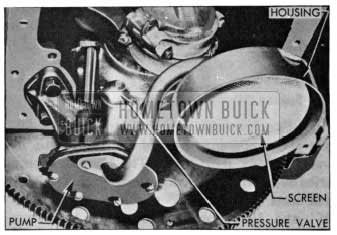
1955 Buick Oil Pump and Screen
Leave A Comment
You must be logged in to post a comment.