8-1 DESCRIPTION OF CHANGES
The steering gear assemblies for both power and manual gears are basically the same as 1954 except that the steering shaft has been shortened approximately one inch for the new steering wheel, the mast jacket has been redesigned for the new transmission controls, and the lower jacket has been redesigned to permit the same transmission controls to be used with either manual or power steering.
- Power Steering Hoses
New pressure and return hoses, used with power steering, are of the tubular fitting type, with improved crimping of the fittings to the hose. These new fittings reduce oil flow noise where the direction of oil flow is abruptly changed. Improved crimping results from the crimp section on the fittings being 1/4″ inch longer than those used in 1954. Serrations inside the fitting have rounded corners which prevent cutting of the hose. See figure 8-1.
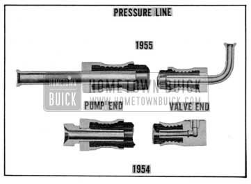
1955 Buick Power Steering Pressure Hose
8-2 STEERING WHEEL REMOVAL AND INSTALLATION
NOTE: Steering wheel puller J-3274 (used previously ) can be reworked so that it may be used to pull the 1955 steering wheel . To rework this puller, first remove the three legs, now on the puller, then drill two (2) holes 11/32″ in diameter to correspond with the holes provided in the steering wheel hub for pulling purposes. Use two (2) cap screws (5/16″ x 18 ) 3″ long in the newly drilled holes.
- Removal of Steering Wheel
- Disconnect wire at horn cable connector on steering column to prevent horn from blowing.
- Remove horn button or operating ring (Par. 10-2) then reinstall steering wheel nut, leaving it backed off several turns.
- Set direction signal switch in “off” position to avoid possible damage to switch operating mechanism.
- Apply Puller J-3274 and pull wheel back to nut. See Figure 8-2.
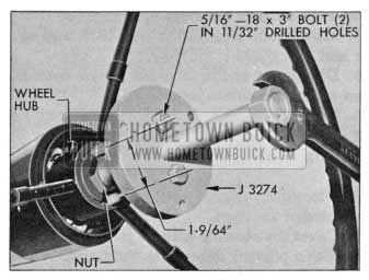
1955 Buick Removing Steering Wheel with Puller J-3274
NOTE : If wheel hub is very tight on shaft, apply a moderate strain with puller, then tap end of puller screw to break hub loose from shaft without distorting wheel hub. Remove puller, nut and steering wheel. See figure 8-2.
- Installation of Steering Wheel
- Before installing steering wheel, set signal switch in “off” position to prevent the switch operating pin from striking and damaging the switch operating mechanism.
- Location marks for proper installation of steering wheel on steering shaft are provided to insure a vertical position of the steering wheel lower spoke when front wheels are in straight-ahead position. The upper end of steering shaft has a small location notch, the solid spoke wheel has a keyway, and the flexible wheel has a mark on the hub. These location marks on shaft and wheel must be in line when wheel is installed.
- With wheel properly located on shaft, install self-locking wheel nut and tighten securely.
- Install horn button or operating ring (Par. 10-2) and connect wire to horn cable connector on steering column.
8-3 REMOVAL AND INSTALLATION OF MANUAL STEERING GEAR
- Removal of Steering Gear
- Place car cover over left front fender then remove the battery.
- Disconnect transmission shift rod from control shaft lower lever. On synchromesh car only, remove selector lever from jacket clamp by removing retainer and spring washer. Loosen bolt in clamp which secures the column jacket to the short tube in gear housing.
- Move front seat all the way back and cover the seat and back.
- Disconnect and remove horn cable connector from steering column jacket.
- On Dynaflow car, disconnect wires from neutral safety switch and remove speed ratio dial light bulb holder from support on steering column jacket.
- Disconnect signal switch wires from fuse block under the cowl.
- Cover the steering column jacket with masking tape to prevent damage to the finish.
- Remove steering wheel (Par. 8-2) and the upper bearing spring and spring seats. Cover the horn contact and threaded end of steering shaft with masking tape.
- Remove signal switch and transmission shift control levers.
- Detach the rubber insulator retainer from dash mat and pull it up about a foot on column jacket. Remove the jute column pad.
- Measure the vertical clearance between the column jacket and the lower surface of instrument panel and record this dimension so that column can be reinstalled in same position. This dimension affects steering wheel height, which may have been changed from normal height to suit the car owner.
- Remove bolts holding the cap to steering column bracket, disconnect the bracket from instrument panel, then pull upward on column jacket to free it from steering gear.
- Remove the cranking motor splash pan from car frame.
- Remove the steering gear to frame lower bolts and clamps, then loosen upper bolts enough so that gear can be tilted sideways to provide room for pitman arm puller. 15. Remove nut and lock washer, then remove pitman arm from pitman shaft, using a suitable puller.
- With another man inside the car to guide the steering column and prevent damage to the column jacket and front seat, carefully lift the steering gear assembly up and forward out of engine compartment, leaving column jacket assembly in the body.
NOTE: As gear assembly is removed be careful not to damage or lose the control shaft return spring, which will be either on end of control shaft or loose on steering shaft.
- Installation of Steering Gear Assembly
Install the gear assembly by reversing the procedure for removal, paying attention to the following points.
- Place control shaft return spring over lower end of control shaft before inserting steering shaft into control shaft.
- When attaching the steering column bracket to instrument panel measure the vertical clearance between the column jacket and the lower surface of instrument panel. The clearance at this point for normal steering wheel height is as follows:
Series 40-60, M /52, M /72: 4/8″ – 3/4″
Models 56C, 56R, 76C, 76R: 3/8″ – 1/2″
The height of steering wheel may be set as much as 3/4″ above or below normal height. If the existing clearance found before removal (Sub. Par. a, Step 11) varies from the normal height specified above, maintain the same clearance and wheel height when steering gear is reinstalled.
When installing transmission control lever, install parts as shown in figure 8-3.
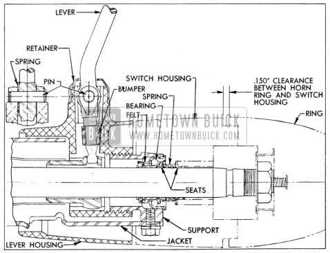
1955 Buick Control Lever and Adjacent Parts
- Install steering wheel with location marks in line.
- When connecting intermediate rod to pitman arm, adjust end plug as specified in the 1954 Shop Manual.
- After installation of horn operating ring, adjust steering column jacket on tube of gear housing as required to provide a clearance of .150″ between the operating ring and signal switch housing. See figure 8-3. Tighten jacket clamp bolt and column bracket cap bolts securely.
- On Synchromesh car, check for proper selection and shifting of transmission as follows:
- In neutral the shift control lever should be slightly above horizontal (about 8 degrees) . It may be necessary to loosen the steering column jacket clamp and shift the clamp slightly to obtain proper position. The mast jacket should remain positioned as described above. A slight adjustment of control rods may be required.
- 7a. On Dynaflow car, adjust the transmission external linkage as specified in Paragraph 5-7 (Sub. Par. b).
- Fill steering gear housing to filler plug opening with multi-purpose gear lubricant as specified for synchromesh transmissions.
- Road test car for ease of steering.
Leave A Comment
You must be logged in to post a comment.