10-1 ACCELERATOR VACUUM SWITCH
- Description and Operation
A Carter accelerator vacuum switch is built into the throttle body on Stromberg and Carter carburetors for 1955. The description and operation remain the same as described in the 1954 Shop Manual.
- Checking Vacuum Switch Timing on Car (Carter and Stromberg)
When the carburetor is installed on engine the following procedure may be used to determine whether the vacuum switch timing is within proper limits. With a Carter carburetor, the method given in Sub. Par. c may be used if preferred.
- Make certain that transmission is in neutral and that parking brake is applied.
- Back off throttle stop screw, rotate fast idle cam to slow idle position if necessary, and fully close the throttle valve. On Dynaflow car, make certain that dash pot will not prevent full closing of throttle valve in the next step.
- Hold a steel 6″ scale, or similar straight edge, against the rear face of the lower arm of the throttle lever which contacts the dash pot, so that scale rests on rocker arm cover. With throttle valve fully closed, make a pencil mark on cover at front edge of scale. See figure 10-1, Step 1.
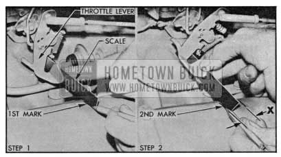
1955 Buick Checking Vacuum Switch Timing on Car
- With ignition switch turned on, slowly open throttle while holding scale in position against throttle lever. At point where the cranking motor is just energized, hold the throttle lever and make a second mark on rocker arm cover at front edge of scale. See figure 10-1, Step 2.
- If vacuum switch is correctly timed, the distance (X) between pencil marks on rocker arm cover will be 29/32″ to 1 7/16;” with a 2-barrel carburetor, or 9/16″ to 15/16″ with a 4-barrel carburetor.
- If necessary, retime switch by changing the number of timing shims. See 1954 Shop Manual, Par. 10-29, c. When switch is correctly timed, set engine idle speed at 450 RPM when hot, and make sure that throttle linkage and dash pot are correctly adjusted.
- Bench Check of Switch Timing on Carter Carburetor
- Bench Check of Switch Timing on Stromberg Carburetor
- Connect a 12 volt battery and test lamp across switch terminals so that lamp will light when switch makes contact.
- Block choke valve open so that fast idle cam is at slow idle position, and back off throttle stop screw to permit full closing of throttle valve.
- While holding throttle valve fully closed, hold a scale (or other strip of metal 5/8″ or more wide against the choke unloader arm of throttle lever and make a pencil mark on float bowl at opposite edge of scale. See figure 10-2, Step 1.
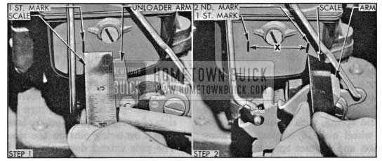
1955 Buick Checking Carter Vacuum Switch Timing
- Slowly open throttle while holding scale in position against unloader arm. At point where the test lamp just lights, make a second mark on float bowl at same edge of scale. See figure 10-2, Step 2.
- If switch is correctly timed, the distance (X) between pencil marks on float bowl will be 15/16″ to 1 5/16″ on the 2-barrel carburetor, or 3/4″ to 1 1/16″ on the 4-barrel carburetor.
- If necessary, retime switch by changing shims as required.
- Connect a 12 volt battery and test lamp across switch terminals so that lamp will light when switch makes contact.
- Block choke valve open so that fast idle cam is at slow idle position, and back off throttle stop screw to permit full closing of throttle valve.
- While holding carburetor in normal upright position, insert a 17/64″ drill between wall of throttle body and lower edge of one throttle valve, at the center. With valve closed against the drill, the switch should make contact and light the test lamp.
- Remove the 17/64″ drill and insert a 9/64″ drill in same position. With valve closed against drill, the switch should be open so that test lamp does not light.
- If switch does not operate within the limits specified, retime it by changing shims as required. See 1954 Shop Manual, Par. 10-29, c.
10-2 HORN BUTTONS
The horn button used with the Series 40 standard steering wheel has a cap with a rubber retainer in its rim which snaps over the rim of a contact cup mounted in the wheel hub. The cap may be pried out with a thin bladed tool and the contact cup and other parts may then be removed by removing the attaching screws and insulating spacer bushings.
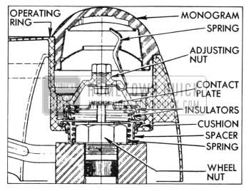
The horn button used with the Deluxe steering wheel has a large operating ring mounted over the wheel hub and spokes. To remove the operating ring, (1) pry out the monogram which is held by the prongs of a retaining spring, (2) unscrew and remove the adjusting nut, (3) remove the contact p)ate arid spring, with insulators, (4) re move steering wheel nut, 5) remove operating ring with cushion and contact spacer. See figure 10-3.
1955 Buick Horn Operating Ring Installation
Install operating ring by reversing the procedure for removal. The steering wheel nut is self-locking and does not require a lock washer. When the con tact adjusting nut is being installed, turn it down until contact is made and horns blow, then back nut off 1/2 turn to provide a proper clearance between contact plate and spacer.
10-3 DIRECTIONAL SIGNAL SWITCH
- Operation
The direction signal switch and its operating mechanism are enclosed in a switch housing on the steering column just below steering wheel.
The switch is operated by a lever projecting from the left side of switch housing. Moving the control lever clockwise sets the switch to indicate a right turn and moving lever counterclockwise indicates a left turn.
The control lever is threaded to screw into a stub shaft anchored to a plate in switch housing which operates the switch. The stub shaft fits into a recess in the housing to provide a bearing or pivot point for the lever and plate. A groove in right side of the lever plate engages the bakelite handle of the switch which is mounted in the lower side of housing below the lever plate. A detent spring mounted in the housing bears against a roller mounted on the lever plate to hold the plate in whatever position it may be set. Bosses in the housing provide stops for the plate when set for either turn. See figure 10-4.
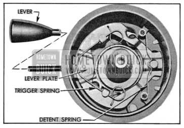
1955 Buick Direction Signal Switch
The trip mechanism for returning the switch to the “off” position after a turn is completed consists of a trigger spring on the lever plate and two switch centering pins on the steering wheel hub. The pins extend down through the lever plate, but when the switch is in the “off” position the lever plate is centered so that the pins ca con tact the trigger spring as the steering wheel is turned.
When the control lever is moved clockwise to set the switch for a right turn the lever plate is moved down, thereby moving the switch handle down and also bringing the upper loop of the trigger spring in to the path of the centering pins. As the steering wheel is turned right and a centering pin contacts the trigger spring, the spring yields to permit the pin to pass without interference. As the wheel is turned left at completion of the right turn, the centering pin pushes the loop of trigger spring against a stop on the lever plate, and this forces the lever plate and switch back to the “off” position.
A similar action but in the opposite direction takes place when the switch is set for a left turn. If the switch is erroneously set to indicate a turn in one direction and the turn is made in the opposite direction, the opposite centering pin will contact the triggering spring and return the switch to the “off” position as the wrong turn is started.
- Replacement of Signal Switch Parts
- Remove steering wheel.
- Set signal switch for a right turn, remove the two switch housing attaching screws, loosen clamp where wiring harness emerges from column
- jacket, then lift housing assembly up over steering shaft. 3. Remove detent spring, unscrew control lever (has two flats near housing for wrench ), then push against lower end of stub shaft to remove lever plate from switch housing.
- If switch and wiring harness require replacement, disconnect wires from fuse block under the cowl and carefully pull harness out of steering column jacket.
- Lay switch housing flat on bench, remove switch attaching screws, switch back with wiring harness, carrier with contactors, and the four small steel balls. See figure 10-5.
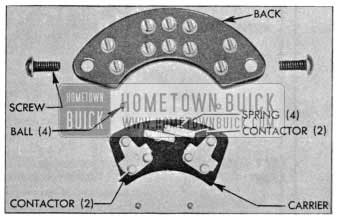
1955 Buick Signal Switch Parts
- When switch parts are being installed, use a small amount of petroleum jelly to hold a steel ball in each of the four bearing grooves in carrier and place carrier in switch housing. Install springs and contactors in carrier as shown in figure 10-5, then install switch back with two screws.
- When switch assembly is reinstalled, tighten wiring harness clamp on column jacket, then connect switch wires to fuse block as shown in the chassis wiring circuit diagrams.
- Before installing the lever plate, apply a light coat of Lubriplate to the switch handle and to the stub shaft of lever plate.
- Install steering wheel and adjust horn ring.
- Figures 10-6, 10-7 and 10-8 show the direction signal circuits when signal switch is set for No Turn, Right Turn, and Left Turn.
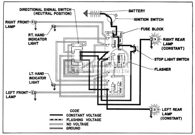
1955 Buick Direction Signal Lamp Circuit Diagram-No Turn Indicated
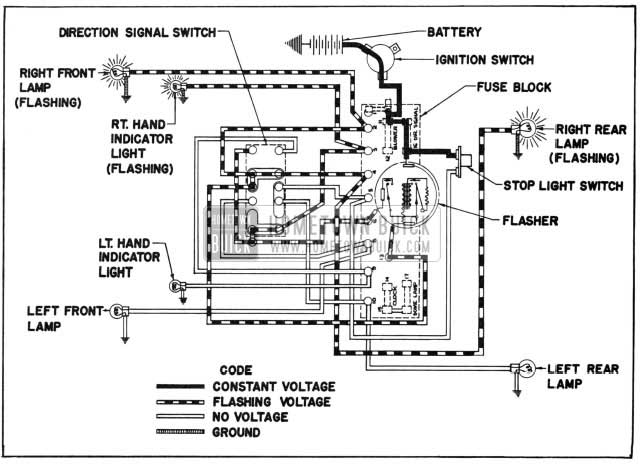
1955 Buick Direction Signal Lamp Circuit Diagram-Right Turn Indicated
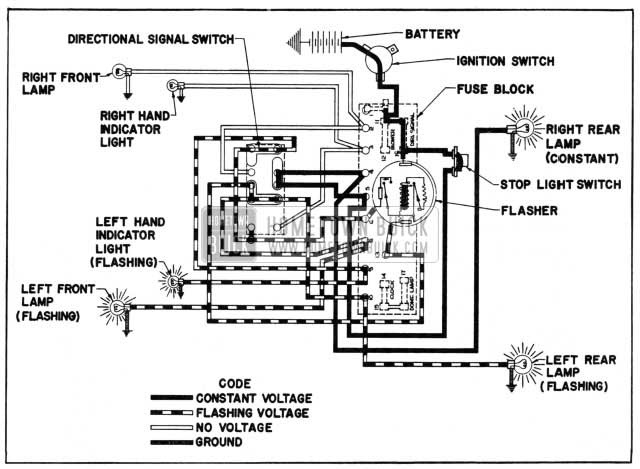
1955 Buick Direction Signal Lamp Circuit Diagram-Left Turn Indicated
Direction signal switch wiring is also shown in the chassis wiring circuit diagrams in figures 10-9, and 10-10.
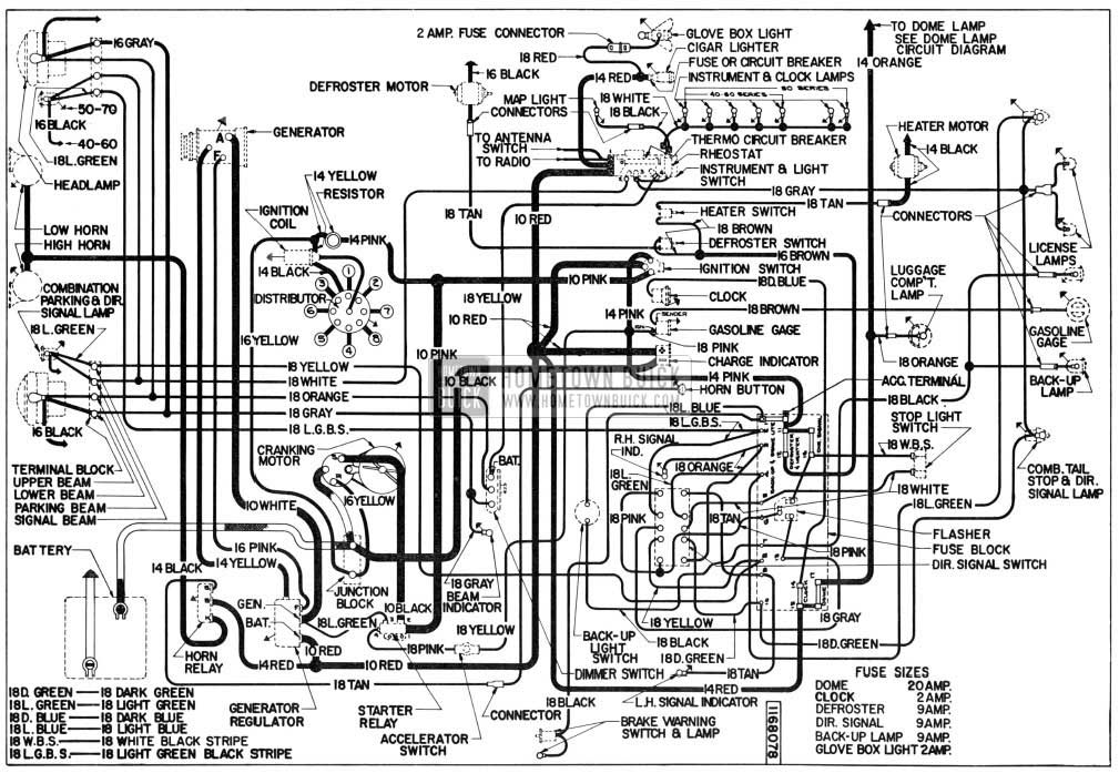
1955 Buick Chassis Wiring Diagram – Synchromesh Transmission
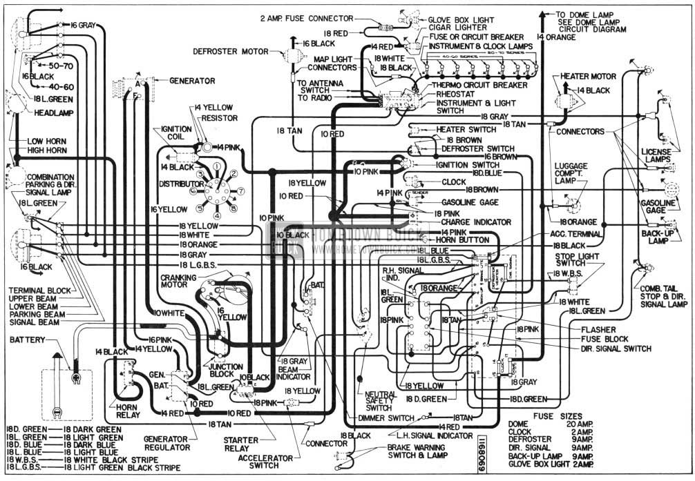
1955 Buick Chassis Wiring Diagram – Dynaflow Transmission
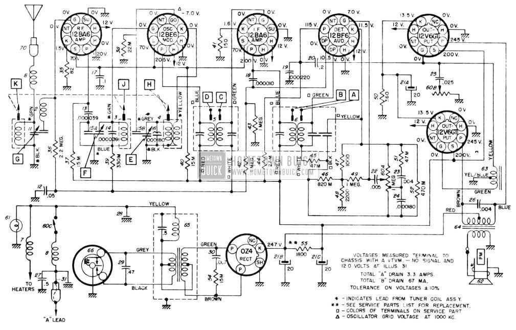
1955 Buick Sonomatic Radio Circuit Schematic
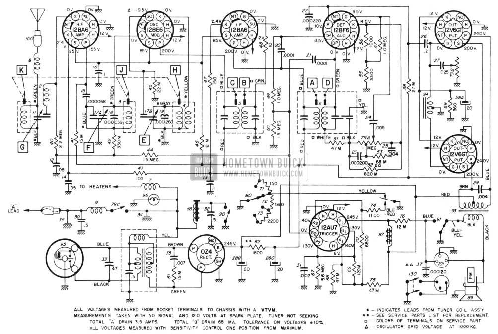
1955 Buick Selectronic Radio Circuit Schematic
1955 Buick Essential Service Tools
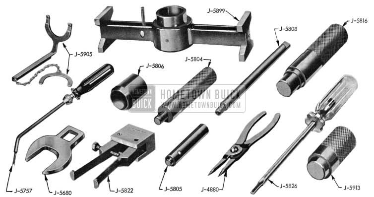
1955 Buick Essential Tools
Part Number – Description
J-4880 – Truarc Pliers
J-5680 – Worm Bearing Adjusting Nut Wrench
J-5757 – Mechanical Weatherstrip lnst.
J-5804 – Mainshaft Endplay Gauge
J-5805 – Air Valve Piston Shim Gauge
J-5806 – Stator Installing Tool
J-5808 – Dial Indicator Support Rod
J-5816 – Reaction Flange Shaft Bushing Installer
J-5822 – Reaction Flange Shaft Bushing Remover
J-5826 – Stator Assembly Screw Remover and Replacer
J-5899 – Converter Clearance Gauge
J-5905 – Pinion Bearing Spacer
J-5913 – Front Stator Blade Carrier Bushing Installer
Leave A Comment
You must be logged in to post a comment.