The Description, Operation, and Service Procedures for the Standard Hydraulic Brakes remain unchanged from 1954, however the Power Brake Cylinder is completely new for 1955. The New Power Brake Cylinder assembly is an air-suspended unit which means that atmospheric pressure is present on both sides of the Power Cylinder Piston when the brakes are in the unapplied position.
Complete details, covering Description, Operation, and Service Procedures appear on the following pages exactly as they will be presented in the 1955 Buick Shop Manual.
Paragraph: Subject
9-15: Description of Power Brake Mechanism
9-16: Removal, Installation, Adjustment of Power Brake Cylinder
9-17: Disassembly, Inspection, Assembly of Power Brake Cylinder
9-15 DESCRIPTION OF POWER BRAKE MECHANISM
- General Description
Wheel brake assemblies used with power brake mechanism are identical with the regular (foot powered ) brake equipment, except that a high pressure type of brake shoe lining is used on the front secondary shoes. This lining is identified by its black colored edge.
The power brake installation has a vacuum actuated power brake cylinder in place of the master cylinder used in the regular hydraulic brake system. The brake cylinder is mounted on the car frame under the body and is connected to the brake pedal by an extended push rod. Reserve fluid is carried in a separate reservoir located under the hood, on the left side, and connected to the hydraulic section of the brake cylinder by a short pipe.
The power brake cylinder utilizes engine manifold vacuum in its operation, as described later, therefore it is connected to the intake manifold through pipes and flexible connections. A vacuum reserve tank of approximately 180 cubic inches capacity is connected into the vacuum line near the power brake cylinder to insure quick and smooth response of the brake cylinder on all power brake applications. A check valve, installed in the vacuum line, closes to maintain existing vacuum at the power cylinder and in the reserve tank whenever manifold vacuum falls below that in the brake system.
When the engine is stopped and check valve is closed, the tank provides sufficient reserve vacuum for two or three normal power brake applications. When reserve vacuum does not exist, the brakes can be applied manually in the same manner as the regular (foot powered) brakes, except that some what more effort is required because of the reduced leverage of the power brake pedal. Since brake application is normally assisted by vacuum, low pedal leverage is used to reduce the total pedal travel.
- Construction of Power Brake Cylinder
The power brake cylinder is the “air suspended” type, meaning that atmospheric pressure is present on both sides of the power piston in the unapplied stage. In the “vacuum suspended” type used in 1953-54 models, vacuum exists on both sides of power piston in the unapplied stage, when engine or vacuum pump is running.
As shown in figure 9-13, a cover closes the forward end of the cylinder housing to form a large chamber in which the power piston and related parts operate. The section on the cover side of the piston will be called the air chamber since it is open to atmospheric pressure at all times. The section on the opposite side of the piston will be called the vacuum chamber since it is subjected to manifold vacuum during power application of brakes. All air entering the cylinder housing passes through an air cleaner core.
The rim of power piston carries a spring expanded leather cup and a felt lubricating wick to seal against passage of air, and an attached guide provides a bearing in the cylinder housing. A flexible rubber hose connecting the piston with a vacuum tee on the side of cylinder housing permits the piston to move back and forth while connected to manifold vacuum. Air is exhausted out of the vacuum chamber through passages in the piston and the vacuum hose when the control valve is set for power application.
The related parts which operate in the cylinder housing with the power piston form a separate assembly composed of: the air valve, floating control valve, hydraulic piston, and the reaction mechanism housed in a pivot plate and cover. This valve and hydraulic piston assembly moves with the power piston as one unit during power application of brakes, but moves alone during manual application, as explained later. A relatively heavy coil return spring is used for the power piston and a smaller and lighter return spring is used for the valve and hydraulic piston assembly.
The hydraulic piston is a solid steel plunger which extends into the hydraulic cylinder through a rubber vacuum cup seal and rubber secondary and primary cups. To prevent vacuum from drawing brake fluid out of hydraulic cylinder in case of seal leakage, the space between the vacuum cup seal and the secondary cup is vented to atmosphere through a hole which is kept open by a loose wire.
Movement of the piston rearward into the fluid filled cylinder displaces a corresponding volume of the fluid, which is forced out into the brake pipes and wheel cylinders. Compensating ports in rear end of the piston permit return of surplus fluid to reservoir when brakes are released. The check valve and spring in the hydraulic cylinder maintains static pressure in brake pipes and wheel cylinders.
- Operation of Power Brake Cylinder
Description of power brake cylinder operation will cover (1) Unapplied Stage (2) Applied Stage (3) Reaction Pressure (4) Poised Stage (5) Releasing Stage (6) Manual Application.
- Unapplied Stage. See figure 9-13.
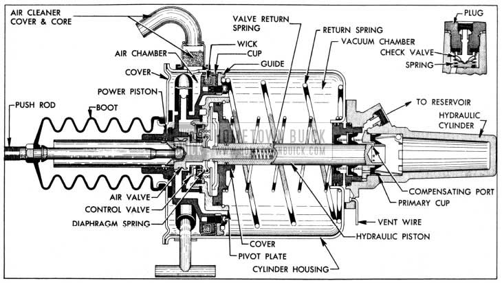
1955 Buick Power Brake Cylinder Unapplied Stage
The pedal return spring holds the push rod and attached air valve forward so that the air valve is held clear of the floating control valve. At the same time, the valve diaphragm spring holds the floating control valve against its seat on the power piston, thereby closing the passage connected to manifold vacuum.
Atmospheric pressure enters through the air cleaner into the air chamber, flows through the boot and air valve into the space between the air valve and the floating control valve, then flows through passages in power piston and out between piston and pivot plate into the vacuum chamber. With the vacuum passage closed and the vacuum chamber open to outside air, the power piston is balanced by atmospheric pressure on both sides and is held against the housing cover by the return springs.
The compensating ports in rear end of hydraulic piston are forward of the primary cup, permitting flow of brake fluid between the reservoir and hydraulic cylinder as required. The check valve is seated to maintain static pressure in the brake pipes and wheel cylinders.
- Applied Stage. See figure 9 14.
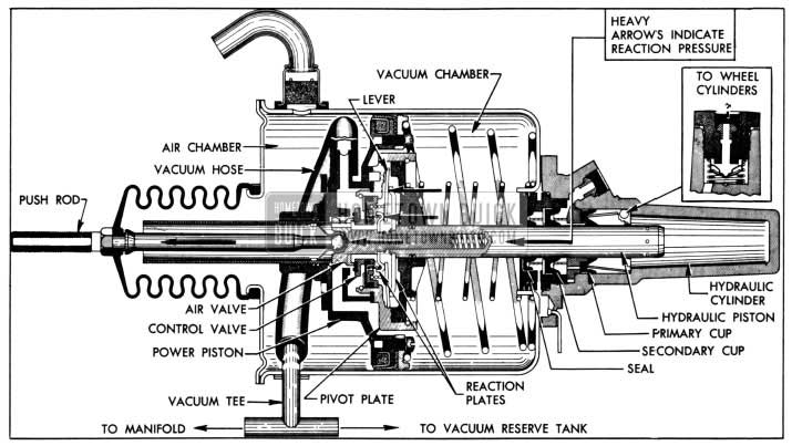
1955 Buick Power Brake Cylinder Applied Stage
As the brake pedal is depressed the push rod moves the air valve rearward until its annular seat contacts the floating control valve, at which point atmospheric pressure is sealed off from the vacuum chamber.
Further movement of the air valve pushes the floating control valve away from its seat on the power piston, thus connecting the vacuum chamber to manifold vacuum through passages in power piston and the attached vacuum hose. As air is exhausted out of the vacuum chamber, atmospheric pressure in the air chamber moves the power piston rearward toward the hydraulic cylinder. The pivot plate is sealed to the power piston and the valve and hydraulic piston assembly moves rearward as a unit with the power piston.
As the hydraulic piston is forced into the hydraulic cylinder, escape of fluid into the reservoir is cut off when the piston compensating ports pass through the primary cup, and the fluid displaced by the piston is then forced out into the brake pipes and wheel cylinders to apply the brake shoes. At the same time, a reaction pressure is transmitted back to the brake pedal to give the driver an indication or “feel” of the pressure being applied to the brake shoes.
- Reaction Pressure. As pressure is built up in the brake pipes and wheel cylinders during brake application, the hydraulic piston is subjected to the same hydraulic pressure. Since the piston is free to move forward in the pivot plate cover, the pressure on the piston is transmitted through the attached reaction plate to the six reaction levers. The outer ends of the levers press against pivot points in the pivot plate and the inner ends press against the valve reaction plate which now bears against a shoulder of the air valve. See figure 9-14.In this manner approximately 40% of the load on the hydraulic piston is transferred through the air valve and push rod to the brake pedal to oppose the foot pressure applied by the driver. This reaction pressure gives the driver a definite indication or “feel” of the pressure being applied to the brake shoes so that he has positive control over the braking operation at all stages.
- Poised Stage. When the desired brake apply pressure is reached and brake pedal is held poised, the power piston continues rearward momentarily until it contacts the floating control valve. See figure 9-15.
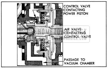
1955 Buick Valves at Poised Stage
At this point, the air valve is also in contact with the control valve so that the passages to the vacuum chamber are sealed off from atmospheric pressure as well as vacuum; therefore the power piston remains stationary or poised, ready to move in either direction as dictated by brake pedal movement.
- Releasing Stage. When foot pressure on brake pedal is released, the pedal return spring pulls the push rod forward to relieve pressure on the air valve. The valve return spring forces the air valve away from the floating control valve, which is seated against the power piston to close the vacuum passage. Since both sides of the power piston are now open to atmospheric pressure, the piston return springs force the power piston and related parts forward to the unapplied position (figure 9-13).As the hydraulic piston moves out of the hydraulic cylinder the fluid from the wheel cylinders flows back into the hydraulic cylinder through the check valve. When the compensating ports in the piston pass forward through the primary cup, any surplus fluid in the hydraulic system can return to the reservoir. The check valve spring presses the check valve against its seat with sufficient pressure to maintain some static pressure in the brake pipes and wheel cylinders.
- Manual Application. When the engine is not running and reserve vacuum is exhausted, the brakes are applied entirely by foot pressure on the brake pedal. As the pedal is depressed, a shoulder on the air valve pushes against the end of the hydraulic piston so that pedal pressure is applied directly to the piston to force it into the hydraulic cylinder. As the valve and hydraulic piston assembly moves rearward, the power piston remains in the unapplied position, where it is held against its stop by its return spring. See figure 9-16.
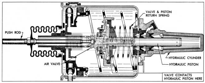
1955 Buick Power Brake Cylinder-Manual Application
This separation of the power piston from its related parts eliminates compression of the heavy return spring, friction of the leather piston cup against the cylinder housing, and movement of air out of the vacuum chamber; consequently the pedal pressure required for manual application is much lighter than if the power piston had to be moved. The only resistance offered in the cylinder housing is the relatively light spring used to return the valve and hydraulic piston assembly to the unapplied position on release of brake pedal.
If the engine should start running while brakes are being manually applied, manifold vacuum would exhaust air from the vacuum chamber through the wide open passages in the power piston, and the power piston would move rear ward and seal to the pivot plate as shown in figure 9-14.
9-16 REMOVAL, INSTALLATION, ADJUSTMENT OF POWER BRAKE CYLINDER
- Removal, Installation of Cylinder
- Adjustment of Brake Pedal and Push Rod
- Remove cranking motor splash pan.
- Disconnect return spring, loosen lock nut on cylinder push rod, remove clevis pin at brake pedal, then unscrew pedal push rod from cylinder push rod.
- Disconnect air inlet hose at air filter on brake cylinder, and disconnect hoses from vacuum tee on opposite side of cylinder.
- Disconnect the reservoir to hydraulic cylinder pipe, allow reservoir and pipe to drain. Disconnect distributor to cylinder pipe and allow to drain. Discard old fluid and cover pipe ends with tape to exclude dirt.
- Remove nuts and lock washers attaching power cylinder to its support and remove cylinder from car.
- Install power cylinder by reversing the procedure for removal. Adjust push rod as described below (sub. par. b ) before installing splash pan.
- After installation is completed, bleed the hydraulic system (par. 9-7 ) and then make sure that reservoir is filled to proper level.
- Check brake system for fluid leaks while applying heavy pressure on brake pedal, with engine running.
- Make certain that brake pedal is properly lubricated and moves freely on its shaft, also that it does not bind on floor mat.
- Make certain that push rod is securely locked in air valve of power cylinder and that boot is properly seated on push rod and flange of housing cover.
- Connect pedal push rod to brake pedal with clevis pin and cotter pin, then check for free movement of pedal and push rod. If a bind exists, loosen pedal shaft bracket bolts to permit bracket to shift to a free position and tighten bolts securely.
- Connect the pedal return spring, then screw the cylinder push rod in or out of pedal push rod until pedal grommet is compressed to approximately 3/4″ after it contacts toeboard with pedal in released position.
- Start engine and apply brakes several times, then check for full release of brakes at each wheel. If brakes drag, readjust push rod. If push rod is too long, compression of the pedal grommet may prevent proper opening of cylinder air valve in brake released position.
9-17 DISASSEMBLY, INSPECTION, ASSEMBLY OF POWER BRAKE CYLINDER
- Disassembly of Brake Cylinder
NOTE: Refer to figures 9-13 and 9-14for identification of parts not otherwise illustrated .
- Mount power brake cylinder in vise with hydraulic cylinder down, being careful not to damage the loose vent pin in flange of cylinder. Tighten vise only enough to hold cylinder firmly; excessive tightening will distort or crack cylinder.
- Remove push rod boot and retainer from housing cover. Do not attempt to remove push rod which is anchored in air valve by a spring type lock.
- Remove air cleaner assembly and disassemble it by removing the screw, gasket, filter core, and spring from the cover.
- Remove housing cover bolts, cover, and gasket. While holding power piston down, disconnect vacuum hose from vacuum tee and remove tee and gasket from housing. See figure 9-17.
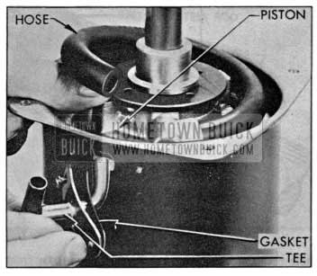
1955 Buick Removing Vacuum Tee
Slowly release power piston to control the pressure of piston return springs as piston and attached parts emerge from housing. Make sure that lip of leather piston cup does not catch in holes in housing.
- Remove power piston from air valve, figure 9-18, then place the valve and hydraulic piston assembly where the polished surfaces of valve and piston will not be damaged by contact with other parts.
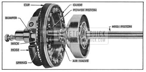
1955 Buick Power Piston With Air Valve and Hydraulic Piston Assembly
- Remove eight screws with lock washers, piston guide, piston cup (leather) , and the felt lubricating wick with expander spring from power piston. Remove rubber stop bumper but leave the O-ring inside piston hub and the vacuum hose for later inspection.
- Support the valve and hydraulic piston assembly in an 8″ length of 3″ pipe, or its equivalent, with push rod up. Remove snap ring then lift the air valve with attached control valve out of pivot plate, and remove the reaction spring. See figure 9-19.
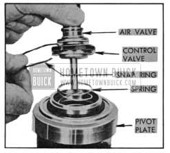
1955 Buick Removing Air Valve with Control Valve
- Remove lock ring, using No. 2 Truarc Ring Pliers J 4880, then remove valve reaction plate, valve diaphragm spring, and control valve and diaphragm assembly from air valve. See figure 9-20.
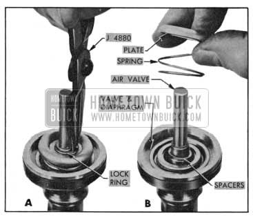
1955 Buick Removing Control Valve from Air Valve
NOTE: One to jour spacers (washers) may be on the middle shoulder of air valve, but some assemblies require none. Note the number of any spacers present, then remove spacers from air valve.
- Remove diaphragm retainer from valve diaphragm, carefully pry off the valve spring retainer, then remove diaphragm and retainer plate from control valve. See figure 9-25.
- Remove air valve return spring from bore of hydraulic piston. Remove snap ring, lift piston with cover out of pivot plate, and remove reaction levers. Remove snap ring, reaction plate, and cover from piston. See figure 9-21.
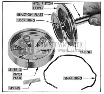
1955 Buick Hydraulic Piston and Attached Parts
- Remove piston return springs from cylinder housing. Remove four nuts and lift housing from hydraulic cylinder. Remove gasket.
- Unscrew and remove cylinder plug from hydraulic cylinder body, using Spanner Wrench J 5794 (fig. 9-22) , then remove secondary cup, cup support, retainer, and vacuum cup seal.
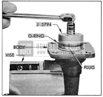
1955 Buick Removing Cylinder Plug
- Remove cup retainer, piston bearing, cup ring, primary cup, and primary cup retainer from cylinder body.
- Remove head nut with gasket, check valve and spring from cylinder body.
- Cleaning, Inspection, Replacement of Parts
As an aid in determining the cause of improper power brake operation, wipe fluid from all rubber parts, then carefully examine these parts for nicks, cuts or other damage. After examination discard all these parts.
Thoroughly clean the remaining parts in diacetone alcohol or clean brake fluid.
CAUTION: Do not use anti-freeze alcohol, gasoline, kerosene , or any other cleaning fluid that might contain even a trace of mineral oil, as this could cause serious damage to all rubber parts in the brake system.
Carefully examine the cleaned parts for nicks, burrs, stripped threads, or other damage. Make certain that the small compensating ports in end of hydraulic piston are clear. If these ports are plugged, clean them thoroughly and flush the hydraulic system to remove all dirt.
If the outer surface of the air valve or the hydraulic piston show evidence of abrasion, polish out light scores with crocus cloth or very fine polishing paper, then wash and dry thoroughly.
If any parts indicate that heavy abrasive action has resulted from severe contamination of the brake fluid, replace damaged parts and be sure to thoroughly flush the reservoir and wheel cylinder lines.
Make sure that the loose pin is properly retained in vent hole in flange of hydraulic cylinder body, and that vent hole is clear.
Do not remove push rod from air valve unless one part is damaged so that replacement is required. To unlock the push rod, prepare a piece of 3/16″ steel rod about 7″ long by filing flats on one end to reduce size to 5/32″, then use as a punch to bend both arms of push rod lock as shown in figure 9-23.
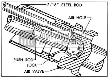
1955 Buick Bending Push Rod Lock
Grip hex of push rod in vise and pull on air valve to separate these parts, then insert thin metal strips through air holes in valve to remove the lock. Use care to avoid damaging the annular seat on air valve.
The Power Brake Cylinder Overhaul Kit (Group 4.898) contains all necessary replacement parts for the power brake cylinder. When reassembling the brake cylinder use all the new parts in the kit regardless of whether the old parts appear fit for use. In addition, replace any other parts which inspection indicates to be unfit for use.
- Assembly of Brake Cylinder
NOTE : Refer to figures 9-13 and 9-14 for identification and location of parts not otherwise illustrated.
- Mount hydraulic cylinder body in vise with flanged end up.
CAUTION: During assembly make certain that no grease or mineral oil comes in contact with internal parts of hydraulic cylinder .
- Install new valve seat washer and new gasket on head nut. Place spring and new check valve (concave side outward ) in cylinder body then install head nut and tighten securely.
- Place primary cup retainer in cylinder body with notched end inward. Dip new primary cup in clean brake fluid and install with flat side outward, using care that cup lip is not turned back at any point. Center the primary cup ring on cup and install piston bearing with notched face outward, pressing bearing down against shoulder in body.
- Dip new vacuum seal and secondary cup in clean brake fluid. Install seal in cylinder plug with flat side inward, center the seal retainer in seal , then install cup support against shoulder in plug. Install secondary cup with flat side inward against the support. Place new 0-ring in the two outer grooves of plug and lightly coat them with silicone grease.
- Center the secondary cup retainer on piston bearing and screw cylinder plug down into cylinder body, using care not to damage 0-ring or secondary cup. Tighten plug firmly, using Spanner Wrench J 5794 (fig. 9-22).
- With housing gasket placed on hydraulic cylinder so that one notch is at vent hole, install cylinder housing with the two large holes for air cleaner on the same side as head nut; install four nuts and tighten securely.
- Install new O-rings on hydraulic piston and the reaction cover, lubricating both 0-rings and the bore of cover with silicone grease. Install piston reaction plate with concave side of rim toward shoulder of piston and install lock ring. Slide cover over piston with concave side toward reaction plate, using care to avoid damaging O-rings.
- Place the six reaction levers in their slots in pivot plate. Install hydraulic piston and cover assembly in pivot plate and install snap ring. Install new rubber seal in groove in small end of pivot plate and lightly coat seal with silicone grease.
- Check for the number of spacers that may be required for proper location of the valve reaction plate, as follows:
- Support pivot plate in 3″ pipe with hydraulic piston downward so that the piston reaction plate rests against the cover and all levers rest on the plate.
- Center the valve reaction plate on reaction levers with rounded side of rim against levers.
- Install Spacer Gauge J 5805 on reaction plate so that long end of plunger extends through to rest on upper end of hydraulic piston. Then note whether upper ends of gauge plunger and sleeve are at same level. Any slight difference in level may be felt with a finger. See figure 9-24.
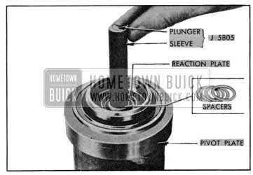
1955 Buick Gauging for Selective Spacers
- Hold the selected spacers, if any, for installation in Step 11.
- (d ) If necessary, install one or more spacers around the plunger and between sleeve and reaction plate until plunger and sleeve are level. If exact level cannot be obtained, select the number of spacers that places end of plunger slightly above rather than below end of sleeve.
- Place fiat side of retainer plate against fiat side of valve diaphragm, push hub of floating control valve through plate and diaphragm, fitting flange of diaphragm into groove in valve, then press spring retainer over hub of valve. Slip outer flange of diaphragm over the smaller side of diaphragm retainer. See figure 9-25.
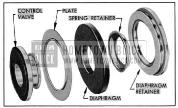
1955 Buick Control Valve and Diaphragm-Disassembled
- Place spacers selected in Step 10 on shoulder of air valve and install floating control valve and diaphragm assembly with rubber valve seat against the seat on air valve. Place valve diaphragm spring over the spring retainer, install valve reaction plate with concave side of rim against the spring, then depress these parts and install lock ring. See figure 9-20.
- Place air valve return spring in bore of hydraulic piston and center the reaction spring on the reaction levers. Lubricate small stem of air valve and rim of rubber diaphragm with silicone grease, install air valve with control valve in pivot plate and install snap ring. See figure 9-19.
- Push one end of vacuum hose all the way up on its tube on power piston, turning hose so that it lays flat against piston. Install rubber stop bumper in groove of piston hub.
- Place the felt lubricating wick in the expander spring, saturate wick with oil specified for Dynaflow transmission, then install in groove of power piston with spring fingers outward and pointing toward bumper end of piston. With leather piston cup retained in the cardboard ring in which it is shipped, install cup over expander spring, making sure it is centered, then install piston guide and attaching screws with lock washers. See figure 9-18.
- Install new 0-ring in the largest groove inside the hub of power piston, coat it with silicone grease and fill the two outer grooves with this grease. Lightly coat rubber seat of control valve with same grease then slide power piston into place over the air valve, using care to avoid damaging O-ring.
- Apply an even coating of Dynaflow oil to inside of cylinder housing, being careful to keep this oil out of hydraulic cylinder. Coat surface of the power piston leather cup with the same oil.
- Center the small piston return spring in cylinder housing, then place the large return spring around it with its smaller end downward, locating the bent end of spring wire between one of the bolt heads and the adjacent dimple pressed in cylinder housing.
- Wipe off hydraulic piston with a clean cloth to remove any oil or grease and apply a film of clean brake fluid to surface of this piston only.
- Remove cardboard retainer ring and place power piston with attached parts on the large return spring so that the bent end of spring wire rests between two of the round bosses on piston guide. Locate the piston so that when it is pressed into housing the side of boss opposite the vacuum hose clears the vacuum tee hole in housing by approximately 3/4″. See figure 9-26.

1955 Buick Position of Piston in Housing
- Push power piston down into cylinder housing, entering the hydraulic piston into hydraulic cylinder, and hold piston down while installing vacuum tee with gasket and two screws. Push end of vacuum hose up on tee about 5/8″.
- Push power piston down and allow springs to return it several times to check for free operation and proper position on springs (step 19), then install gasket and cover on cylinder housing with four bolts, lock washers and nuts tightened securely.
- Place hair pin spring and filter core in air cleaner cover, snap the rubber gasket over flanged edge of cover, and install this assembly on housing with screw and gasket. The tube must point toward air valve.
- If push rod was removed from air valve, place a new lock over ball end of push rod and press parts into air valve until both ends of lock snap into place behind the shoulder inside air valve.
- Install push rod boot so that it fits on groove on rod and over the flange on housing cover. Wrap the retainer around boot where it fits over cover and lock in place.
NOTE: To assist in parts identification, an exploded view of the Power Brake Cylinder for 1955 is shown in figure 9-27.
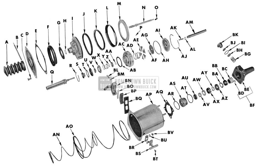
1955 Buick Power Brake Cylinder
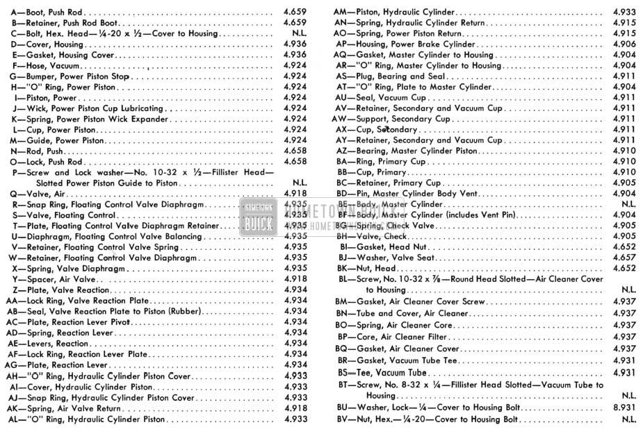
1955 Buick Power Brake Cylinder Legend
Leave A Comment
You must be logged in to post a comment.