3-1 FUEL SYSTEM CHANGES
- Carburetors
A new larger 4-barrel carburetor is used .on Series 60-50-70 engines. A 4-barrel carburetor replaces the 2-barrel carburetor previously used on Series 50 engines. The 1955 carburetor has increased throat diameters which increase efficiency and power output, and is 5/16″ lower in height which allows a decrease in hood line.
Both Stromberg and Carter carburetors are equipped with a Carter vacuum switch assembly. Service procedures remain basically the same as 1954 except for vacuum switch timing which is described in Par. 10-1.
- Air Cleaner and Silencer
A new air cleaner and silencer assembly is used on Series 60-50-70 engines in 1955. The air cleaner itself is unchanged but since it is mounted on a 5/16″ lower carburetor, the silencer has been made smaller in diameter and therefore the top of the complete assembly is 5/16″ lower than in 1954.
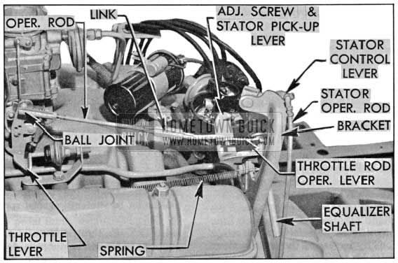
- Throttle and Stator Linkage
A revised version of 1954 Throttle Linkage is used for 1955, having been developed to meet the needs of the new transmission with a variable pitch stator. The throttle linkage serves a dual purpose, operating the carburetor throttle valves from fully closed to wide open position, and regulating the transmission stator blades in either its “Cruise” (low angle) or “Performance” (high angle) position. The main part of accelerator pedal travel operates the carburetor throttle valves only (with the stator blades in the low angle position ) while the last one-half inch of travel operates the stator control valve linkage which shifts the stator blades to the high angle position.
To simplify description and operation of throttle linkage, the mechanism will be described in two sections; throttle control and stator control linkage.
Throttle control mechanism consists of an equalizer shaft with a lower lever extending to the accelerator pedal and an upper lever connected to the throttle operating rod. The throttle operating rod is equipped with a link which provides adjustment so that the throttle control mechanism can operate the stator control mechanism before or after the throttle valves reach the wide open position.
Stator control mechanism is incorporated with the throttle mechanism and consists of a stator pick up lever which is in position on the equalizer shaft to be rotated with the upper throttle operating lever whenever the throttle valves are opened. When the throttle valves reach a pre determined opening, the pick up lever engages a stator valve operating lever which pivots on the upper mounting bracket to operate linkage to the stator control valve. See figures 3-1 and 3-2.
1955 Buick Throttle and Stator Control Linkage-Closed Throttle
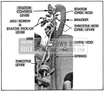
1955 Buick Throttle and Stator Control Linkage-Open Throttle
All Dynaflow equipped cars shipped from the factory will be set to have full throttle and stator high angle position reached simultaneously. With this set up, the throttle operating rod is adjusted to become a solid rod between the throttle lever and equalizer shaft.
Another adjustment is provided so that the carburetor throttle valves are in the wide open position before overtravel in the control mechanism allows stator control linkage to shift the stator blades to the high angle position. With this arrangement, the throttle operating rod is adjusted so that further travel of the accelerator pedal, after the throttle valves are fully open, will merely compress an overtravel spring in the link and literally “stretch” the operating rod to con tact stator control linkage.
Either arrangement is available through adjustment described in Paragraph 3-3.
3-2 INTAKE AND EXHAUST
- Intake Manifold
New and larger intake manifolds, which reduce flow restrictions by increasing the cross sectional area of the inlet branches, are being used on all engines for 1955. The inlet passages in both the 2-barrel manifold (used on Dynaflow engines) and 4-barrel manifolds (used on both Synchromesh and Dynaflow engines) remain identical to each other, the only difference between these two manifolds being in the carburetor mounting pad.
On the 40 Series Synchromesh cars, a new manifold will be used in which a revised heat jacket is employed. The exhaust heat passes under and around the carburetor riser providing better warm-up characteristics. In other respects, the manifold is similar in design to those used on Dynaflow engines.
3-3 THROTTLE AND STATOR LINKAGE ADJUSTMENT
- Carburetor
NOTE: Before attempting adjustment of throttle and stator control linkage, be certain the following carburetor settings are correct:
- Hot Idle (450 RPM)
- Fast Idle
- Choke Unloader
- Adjustment to Obtain Stator High Angle Position, Simultaneously with Wide Open Throttle
Prior to making any adjustments be certain the floor mat is properly positioned, the linkage up to the carburetor lubricated and free, the attaching screws, bolts, etc, are properly tightened, and that the accelerator pedal can move the throttle valves smoothly from the fully closed, to the wide open position. Also be sure the return spring is strong enough to fully close the throttle valve.
- Disconnect the throttle return spring, then detach the throttle operating rod from the rod operating lever and loosen the clamp bolt which secures the lever to the equalizer shaft.
- Back off the stator pick-up lever adjusting screw until the screw end is flush with the lever surface.
- Adjust the carburetor end of the operating rod until approximately 5/8″ threads remain exposed, then tighten lock nut.
- Rotate link on rod (as if threading a R.H. nut) toward the front of the throttle rod until the rod cannot be stretched against spring tension of the link-figure 3-3.
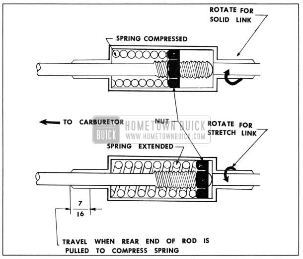
1955 Buick Stretch Link-Throttle Operating Rod Assembly
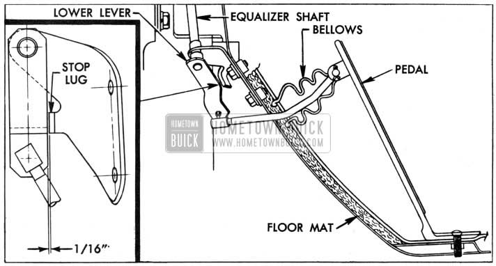
1955 Buick Lower Lever to Stop Lug Clearance
A minimum clearance of 1/16″ should exist. Then depress the accelerator pedal firmly against floor mat, checking to see if choke unloader is operating properly.
- Adjustment to Obtain Stator High Angle Position after Wide Open Throttle
- Disconnect the throttle return spring, then detach the throttle operating rod from the rod operating lever and loosen the clamp bolt which secures the lever to the equalizer shaft.
- Back off the stator pick-up lever adjusting screw until the screw end is flush with the lever surface.
- Adjust the carburetor end of the operating rod until approximately 5/8″ threads remain exposed, then tighten lock nut.
- Rotate link in rod (as if removing R.H. nut, see figure 3-3) from the front of the throttle rod until the rod can be stretched approximately 7/16″ against spring tension of the link. (Measure stretch at forward end of link.)
- With the throttle lever in the hot idle position and the accelerator pedal held fully upward, position the throttle rod operating lever on the equalizer shaft so that the operating rod will extend approximately 1/16″ past hole in lever. Tighten clamp bolt.
- Attach the operating rod to the throttle rod operating lever, making certain the retaining clip is in place, then connect the throttle return spring to the pick-up lever.
- With the throttle lever in the hot idle position, check the clearance between the lower equalizer lever and the stop lug on the cowl mounting bracket. A minimum clearance of 1/16″ should exist. Then depress the accelerator pedal firmly against the floor mat, checking to see if choke unloader is operating properly.
- If the 1/16″ clearance in Step No. 7 does not exist or if the choke unloader is not operating properly, readjust the operating rod length at the carburetor (threaded ) end, or change the position of the throttle rod operating lever on the equalizer shaft one serration at a time until proper settings are obtained.
- With the pedal firmly depressed against the floor mat, thread the stator pick-up lever adjusting screw against the stator operating lever, raising it until all vertical play is removed from the stator operating rod, then back screw off 1/2 turn. In this position a slight clearance should exist between stator crank operating lever and stop pin on high accumulator.
- When linkage is set for over-travel, the stop on the throttle lever must contact boss on throttle body before accelerator pedal can be pressed to floor mat against tension of stretch link spring.
- Recheck linkage for smooth operation and adjust dash pot.
NOTE: Since carburetor and stator control linkage operate together, if one section of the linkage is disturbed for any reason, the other should be checked for correct settings.
Leave A Comment
You must be logged in to post a comment.