The 1953 Buick Twin Turbine Dynaflow transmission has a completely new 4-element torque converter. The new converter has two turbines interconnected through a simple planetary gear set in place of the single turbine previously used.
Compared with previous models, the Twin Turbine converter has one pump in place of a primary and a secondary pump, one stator in place of two, and consequently only one free wheeling clutch (in stator) instead of three. The new reaction shaft is shorter and the input shaft and bell housing have been changed to accommodate new converter parts.
The 1953 Buick Twin Turbine Dynaflow installation with the V-8 engine includes the following additional changes:
- Rear bearing retainer and output shaft are 5 1/4″ longer.
- Planet carrier and reverse ring gear revised.
- Speedometer gear located higher.
- Access hole and cover added for adjustment of valve operating rod.
- Oil cooler mounted under rear bearing retainer.
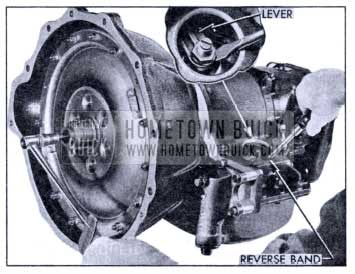
- New shift lever, range indicator, lever and roller type detent, and stop plate in steering column.
The turbine planetary gear set and improved vane design in all elements provides higher torque multiplication at stall and better car performance at low speeds. Under stall conditions, the maximum torque multiplication in the new converter is 2.45 to 1, compared to 2.25 to 1 in the 1952 converter. The improvement in relationship between car speed and engine revolutions (for M/52) is shown in the following table.
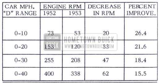
1953 Buick Engine RPM
TWIN TURBINE CONYERTER CONVERTER PUMP

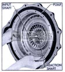
1953 Buick Twin Turbine Dynaflow Converter Assembly
The converter pump is similar to the primary pump used in previous models except that the vanes are of different form and the hub is cut off where the secondary pump was formerly mounted. The hub of the pump cover is changed to conform with changes in the turbine mounting.
TWIN TURBINE ASSEMBLY

1953 Buick Twin Turbine Dynaflow Pump, Turbines and Stator
The twin turbine assembly consists of a first turbine, a second turbine, and a planetary gear set that connects the first turbine to the second turbine and the transmission input shaft.
The first turbine has a narrow band of vanes located between the pump exit and the second turbine. The second turbine is located inside the first turbine in position to receive all oil that flows through it from the pump. This turbine has a broad band of vanes which are shaped to direct the oil flow back into the stator in a direction opposite to converter rotation.

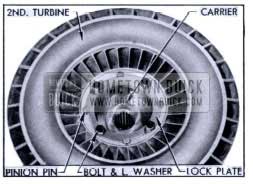
1953 Buick Twin Turbine Dynaflow Converter Turbine Mountings
The second turbine is bolted to a turbine carrier which is splined to the input shaft, therefore the second turbine and shaft rotate at the same speed.
The first turbine is mounted on a disk and hub assembly which has a bearing on the hub of the turbine carrier. This turbine is connected to the carrier and input shaft through the planetary gears, therefore its speed relative to the input shaft is governed by gear action.

1953 Buick Twin Turbine Dynaflow Turbine Planetary Gears
The first turbine hub contains internal ring gear teeth which mesh with four planet pinions mounted in the turbine carrier on steel pins and needle bearings.
The planet pinions mesh with a sun gear which is supported by a bearing on the input shaft. The sun gear is coupled to the stator free wheel cam so that the gear is held stationary whenever the stator is held stationary by the free wheel clutch.
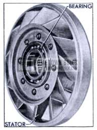
CONVERTER STATOR

1953 Buick Twin Turbine Dynaflow Converter Stator
Improved vane design in all elements permits smooth redirection of oil flow from turbine to pump with the single stator that replaces the primary and secondary stators used in previous models. The stator is mounted on the reaction shaft by means of a free wheeling clutch similar to previous stators.
When the transmission is used with the 8-in -line engine the stator has 12 broad vanes; when used with the V -8 engine the stator has 20 narrow vanes. This difference in stator design adapts the one converter to the different output torques of the two engines. All other converter parts are identical for all series.
OPERATION OF TWIN TURBINE CONVERTER
The hydraulic principles by which the Twin Turbine converter multiplies engine torque are the same as for previous models, which are explained in detail in the 1952
Shop Manual. Operation of the converter has been simplified by elimination of the secondary pump and one stator, but a new operating feature has been added by the geared first turbine.
When the car is stationary, with transmission in Direct Drive and engine idling, the engine driven converter pump projects a rotating cylinder of oil into the first turbine, through which it flows into the second turbine. At idling speed the force of oil flow against the vanes is not sufficient to move either turbine, therefore, the oil flows through the turbines into the stator without transmitting any appreciable amount of torque.
As the oil emerges from the second turbine near its center, the backward curvature of the exit ends of the vanes causes the oil to spin backward with reference to pump rotation as it flows into the stator. Pressure of oil against the forward face of the stator vanes causes the free wheeling clutch to lock and hold the stator (and sun gear) stationary. The curved stator vanes then change the direction of flow so that the oil enters the pump rotating in the same direction as the pump is turning.
When the throttle is opened the engine speeds up and rapidly approaches its torque peak. With increased speed, the converter pump now projects a large volume of oil into the first turbine at high speed. The resulting force of oil against the vanes causes the turbine to rotate in the same direction as the pump.

1953 Buick Twin Turbine Dynaflow Turbine and Gear Operation
As the first turbine rotates it absorbs part of the energy transmitted by the oil stream and converts this energy into torque, which is imparted to the ring gear in its hub. The ring gear rotates the planet pinions, causing them to “walk” around the stationary sun gear so that turning force is applied to the turbine carrier in which the pinions are mounted. The carrier transmits this torque to the input shaft.
The gear tooth combination gives a ratio of 1.6 to 1 when the sun gear is stationary, meaning that the first turbine turns 1.6 revolutions to one revolution of the input shaft. This reduction gearing increases the torque trans mitted through the first turbine.
The second turbine absorbs energy from the oil stream after it leaves the first turbine and converts this energy into torque which is imparted directly to the input shaft through the turbine carrier on which it is mounted.
As the car gains speed and momentum the demand for torque decreases so that the applied torque causes the speed of both turbines to rapidly approach pump speed. Accompanying the reduction in speed differential between the turbines and pump is a corresponding decrease in the effectiveness of the first turbine, thus lowering the torque reaction on the sun gear until this reaction is entirely eliminated.
With increased speed of the second turbine the direction of oil flow changes from the forward to the rear faces of the stator vanes, thus gradually eliminating the force holding the stator stationary. Pressure against the forward face of the stator vanes and torque reaction against the sun gear ceases at approximately the same speed, after which the stator and gear free wheels. The free wheeling stator presents little or no interference with the flow of oil between the second turbine and the pump.
When the sun gear is released by the stator free wheeling clutch the first turbine ceases to be effective. The speed of the second turbine increases until both turbines are rotating at nearly the same speed as the pump. During this same period the speed of the freewheeling stator and sun gear increases and approaches turbine speed.
At this point the torque converter functions as an efficient fluid coupling, transmitting torque at a 1 to 1 ratio. Sufficient speed differential remains between pump and turbines to enable transfer of oil from pump to turbines where the oil gives up energy and returns to the pump for recirculation.
The transition from a maximum torque multiplication of 2.45 to 1 under stall conditions to a 1 to 1 ratio when operating as a fluid coupling is made without noticeable steps or stages. The described operations of the turbines and stator do not occur at set car speeds but are dependent on torque requirements imposed by car operating conditions.
With light loads and steady driving conditions, torque multiplication may cease at very low car speeds, but with continued acceleration some degree of torque multiplication may be present throughout the major portion of the car speed range. When operating conditions change to increase torque demand, the converter automatically adjusts itself to meet this demand with out driver manipulation of any controls.
TWIN TURBINE CONVERTER SERVICE OPERATIONS

1953 Buick Twin Turbine Dynaflow Converter – Front View
REMOVAL OF CONVERTER UNITS
- Remove large hex plug and gasket from hub of converter pump cover, then remove the socket set screw and lock washer located in the hub, using hex wrench (5/16″ across flats).
- Remove all nuts, plain washers, and bolts attaching cover to converter pump. A punch inserted through bell housing hand hole into a drive bolt hole will hold pump from turning.
- Remove cover from pump, tapping or prying against the edge to loosen it. Check the cover seal for damage or evidence of oil leakage before removing it from cover.
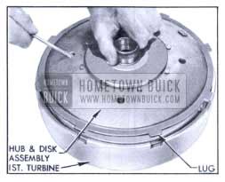
1953 Buick Removing Dynaflow Twin Turbine Assembly
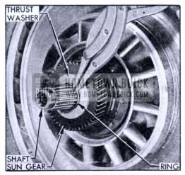
1953 Buick Retaining Ring, Washer and Sun Gear
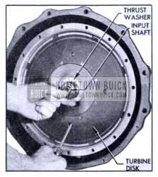
Insert screwdriver into a hole in the first turbine disk to aid in removing the twin turbine assembly from the input shaft. Push inward on shaft to avoid with drawing it. Remove bronze thrust washer from turbine hub.
1953 Buick Stator Installation
1953 Buick Removing Converter Pump
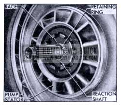
Remove retaining ring from groove in reaction shaft and slide the converter stator and free wheel roller race from reaction shaft. Remove stator bearing from reaction shaft if it did not come out with the stator.
DISASSEMBLY OF CONYERTER UNITS
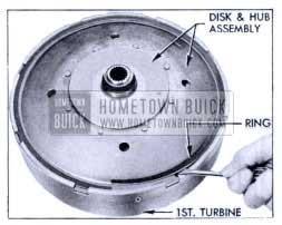
1953 Buick Removing Retaining Ring
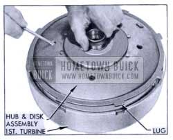
1953 Buick Removing Disk and Hub Assembly
- Pry disk retaining ring out of groove in first turbine, insert screwdriver in a hole in the disk and lift disk and hub assembly out of first turbine. Tap on center of second turbine to separate the parts if necessary.
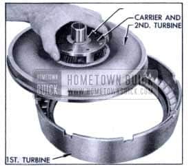
1953 Buick Removing Turbine and Carrier Assembly
Lift the second turbine and carrier assembly out of first turbine.
1953 Buick Turbine, Carrier and Lock Plate
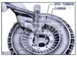
1953 Buick Removing Carrier from Turbine
Remove four turbine-to-carrier bolts and lock washers, then remove the pinion pin lock plate.
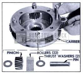
1953 Buick Disassembling Turbine Carrier
Remove pins and planet pinions from turbine carrier, then remove thrust washers and bearing rollers (22) from each pinion.
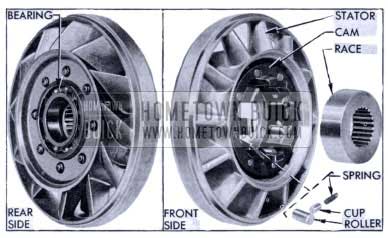
1953 Buick Stator and Free Wheel Parts
Remove ball bearing from rear side of converter stator, push the free wheel roller race out of the free wheel cam in front side of stator, then remove all rollers, cups, and springs from the cam.
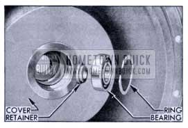
1953 Buick Input Shaft Pilot Bearing and Retainers
Pry the pilot bearing retaining ring out of its groove in hub of converter pump cover 1 then push the pilot bearing and bearing retainer out of the hub.
INSPECTION OF CONVERTER PARTS
- Wash all parts in clean solvent and dry thoroughly.
- Inspect all bearings, thrust washers, bushings, and related bearing surfaces for excessive wear, scoring or other damage.
- Inspect rear edge of first turbine hub (at ring gear) and the mating thrust surface on second turbine (around carrier) for wear, scoring or other damage.
- Inspect all planetary gear teeth for wear or scoring.
- Inspect converter pump hub for scores and for wear caused by the front oil pump seal and inspect the seal in oil pump for wear or damage.
- Inspect free wheel roller springs for distortion and check rollers and race for nicks or burrs. Small nicks or burrs should be removed with an Arkansas stone and polished with crocus cloth.
- Inspect vanes of converter pump, turbines and stator for damaged or cracked vanes.
- Replace all worn or damaged parts.
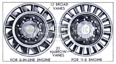
1953 Buick Two Types of Stators
If a stator is replaced, make certain that the new part is correct for the transmission. In a transmission used with the 8-in-line engine the stator has 12 broad vanes; when used with the V-8 engine the stator has 20 narrow blades.
ASSEMBLY OF CONVERTER PARTS
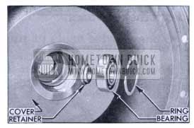
1953 Buick Pilot Bearing and Retainers
- Place the input shaft pilot bearing retainer in the hub of converter pump cover with the shouldered side upward.
- Push the pilot bearing into hub of cover until the outer race bears against shoulder in hub.
- Install retaining ring in groove in hub above the bearing.
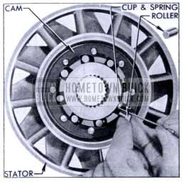
1953 Buick Installing Free Wheel Roller
1953 Buick Bearing Installed in Stator
Install springs and cups and the free wheel roller race in the cam on front side of converter stator, then use a suitable thin blade to depress the cup and spring while inserting each of the free wheel rollers.
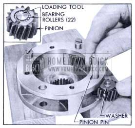
1953 Buick Installing Pinion in Carrier
Support the turbine carrier on two wood blocks with the hub side down, then assemble and install four pinions as follows.
NOTE: A loading tool made locally of steel rod 3/8″ in diameter by 11/16″ long will simplify loading and installation of pinion.
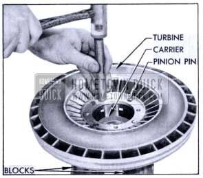
1953 Buick Installing Turbine on Carrier
Use a hammer and hardwood dowel or other soft punch to tap the turbine down over the carrier. Avoid distortion of turbine by using light blows applied mid way between holes and alternated from side to side to keep parts square with each other.
NOTE: If turbine cannot be assembled on carrier with moderate force, remove it and check for burrs in counter bored recess.
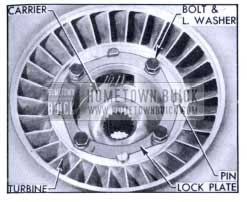
1953 Buick Lock Plate Installation
1953 Buick Installing Disk and Hub Assembly
Install pinion pin lock plate so that it enters the notches of all pins, then install the four turbine to-carrier bolts with lock washers.
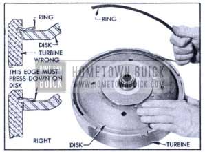
1953 Buick Installing Disk Retaining Ring
Note that the turbine disk retaining ring is “dished”. Place the ring in position with the “dish” upward. so that the inner edge will bear firmly against the disk when the ring is engaged in the groove in first turbine.
INSTALLATION OF CONVERTER UNITS
- Install the converter pump on reaction shaft, turning it until lugs on pump hub enter the slots in front oil pump driving gear.
1953 Buick Stator Installation
Make sure that the ball bearing is properly seated in the converter stator, then install this unit on the reaction shaft. Push against the roller race to keep it from sliding out of place.
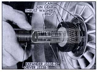
1953 Buick Installing Retaining Ring
Install sun gear on input shaft and mesh it with free wheel cam in the stator, then install the bronze thrust washer on shaft.
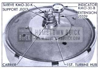
1953 Buick Dial Indicator on Turbine
Use Sleeve KM0-30-K to mount Dial Indicator KMO-30-B on Support J 1013. Attach Extension J 5339 to plunger of indicator.
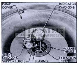
1953 Buick Dial Indicator on Pump Cover
Support converter pump cover in a horizontal position and lightly tap the input shaft pilot bearing down against shoulder in hub of cover.
The following thrust washers are available:
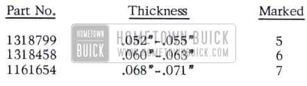
1953 Buick Thrust Washer Thicknesses
- Install twin turbine assembly on input shaft, turning it as required to mesh the planet pinions with the sun gear.
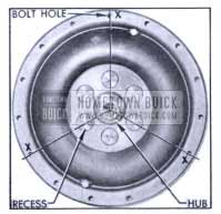
1953 Buick Location of Driving Bolt Holes
Looking at front face of converter pump cover, select the three bolt holes (X) that are aligned with the center of the hub and one of the counterbored recesses adjacent to hub. Mark these holes for later installation of the flywheel-to-pump driving bolts.
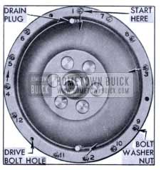
1953 Buick Bolt Tightening Sequence
Install bolts with plain washers and special nuts in all but the three driving bolt holes, but do not tighten bolts.
When tightening bolts, insert a wide screwdriver blade between flat side of bolt head and the pump to pre vent a corner of bolt from digging into pump casting.
1953 Buick Tightening Set Screw
Screw the socket set screw with lock washer into the input shaft through opening in pump cover hub.
1953 BUICK TWIN TURBINE DYNAFLOW TRANSMISSION CONTROLS
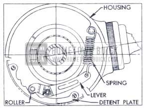
1953 Buick Detent Lever and Plate
The transmission control mechanism in the Series 50 steering column has been redesigned for easier shifting.
The control lever housing is externally mounted on the upper end of the column jacket. The housing contains a spring loaded lever and roller which engages notches in a detent plate anchored to the underside of the signal switch housing. When the control lever rotates the housing and control shaft during shifts, the detent roller moves easily along the notches in the plate but provides a firm detent in the selected position.
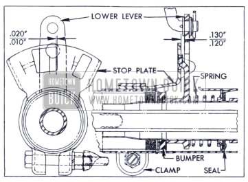
1953 Buick Lower Lever and Stop Plate
A stop plate is mounted on the column jacket in position to engage a tongue on the control shaft lower lever. The control lever must be raised toward the steering wheel when shifting into Reverse, Neutral or Parking. The control lever raises the control shaft against pres sure of a return spring, and this lifts the lower lever clear of the stop plate.
With control lever in “Drive” position, a clearance of .120″ to .130″ (1/8″) must exist between the lower lever and stop plate. A clearance of .010″ to .020″ must also exist between the tongue on lever and the nearest edge of the large hole in stop plate. The stop plate may be adjusted as required after loosening the clamp bolt.
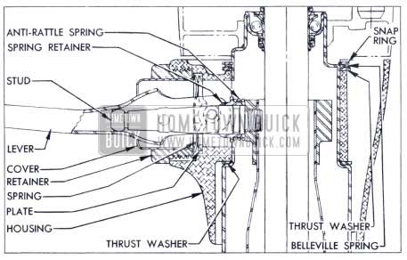
1953 Buick Control Lever and Housing Parts
The control lever and related parts may be removed by first unscrewing the lever retainer from housing, then removing the lever cover, retainer spring, retainer plate, and lever. Remove the anti-rattle spring retainer and spring from the control lever stud, then unscrew the stud from control shaft.
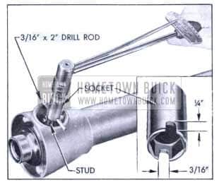
1953 Buick Installing Control Lever Stud
When the control lever stud is installed in control shaft, it is very important to tighten it to 25-30 ft. lbs. torque. Use a torque wrench equipped with a long 9/16″ socket which has notches cut to fit a piece of 3/16″ (.187″) drill rod inserted through the hole in stud. See details in figure D-39.
Adjustment of 1953 Buick Twin Turbine Dynaflow manual control linkage is similar to procedure given in the Shop Manual for 1952 Models. This procedure is given in revised form in the 1953 Product School Manual.
Leave A Comment
You must be logged in to post a comment.