The large bore and short stroke with use of short connecting rods, combined with the V-type cylinder arrangement, permits a very compact 1953 Buick fireball engine design of minimum height, width, length and weight. The new 1953 Buick fireball engine is 13.6 inches shorter and weighs 213 pounds less than the 1952 Series 70 8-in-line engine.
In addition to compactness, the large bore and short stroke design permits lower piston speeds and decreased piston travel which are beneficial in reducing wear of pistons, rings, and cylinder walls. Friction is also reduced, permitting more of the fuel energy to be delivered as output power.

1953 Buick Fireball V8 Engine – End Sectional View
The compact design permits a more rigid crankshaft having a lower moment of inertia around its center of rotation. The more rigid crankshaft with the lowered moment of inertia increases the critical speeds of torsional vibration to well above the maximum operating speed of the 1953 Buick fireball engine.
CYLINDER CRANKCASE
The cylinder crankcase has two banks of four cylinders each, which form a 90 degree angle (V). The crankcase section extends below the centerline of the crankshaft to form a continuous flat surface with the rear bearing cap and the timing chain cover, permitting installation of the lower crankcase with a one-piece gasket. The upper portion of the flywheel housing is cast integral with the cylinder crankcase.
The right bank of cylinders (as viewed from rear) is set slightly forward of the left bank so that connecting rods of opposite pairs of cylinders can be connected to the same crankpin. Starting at front end, cylinders in the right bank are numbered 1-3-5-7 and cylinders in the left bank are numbered 2-4-6-8.
CRANKSHAFT AND BEARINGS
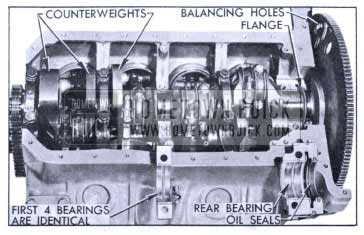
1953 Buick Crankshaft and Bearings
The crankshaft is supported in the crankcase by five steel-backed full precision type bearings, all having the same nominal diameter. The first four bearings are identical, but the rear bearing is longer and flanged at both ends to match flanges on the crankshaft which control end thrust.
The crankshaft is counterbalanced by weights forged integral with crank cheeks. Maximum counter weighting in the space available is obtained by machining the weights to a contour which allows a minimum uniform clearance with cylinder barrels and piston skirts.
Additional counterbalancing is obtained by holes punched in the flywheel and by a heavy section of metal on one side of the fan driving pulley. This engine does not use a harmonic balancer.
CONNECTING RODS AND PISTONS
Connecting rods are 2 1/4″ shorter than rods used in the 1952 Series 70 engine. The lower end of each rod is fitted with a steel-backed full precision type bearing. The slotted upper end of the rod has a bolt for clamping the piston pin, which floats in the bosses in the piston.
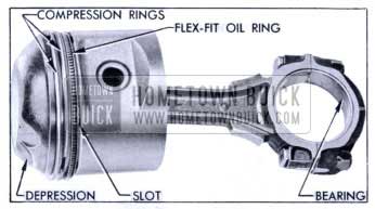
1953 Buick Connecting Rod and Piston Assembly
The Anodized aluminum alloy pistons have full skirts and are cam ground. Each piston has two cast iron compression rings and one Flex-Fit oil control ring located above the piston pin. Two transverse slots in the oil ring groove and six small slots at lower edge of groove extend through the piston wall and permit drain back of oil collected by the oil ring.
An important design feature is the flattened dome shape of the piston head. The sides of the dome conform closely to the contour of the combustion chamber in the cylinder head. Shallow depressions cast into the dome provide clearance between the piston and valves in operation.
COMBUSTION CHAMBERS
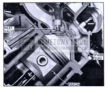
Each combustion chamber in the cylinder head is machined to a dome shaped contour which is somewhat elongated to accommodate the valve ports located in the upper side. With the flattened dome shaped piston head it provides a very compact chamber having a minimum length of flame travel from the centrally located spark plug to the extreme edge of the effective portion of the combustion space.
All valves are mounted vertically in the cylinder head and in line from front to rear, so they operate at 45 degrees to the centerline of cylinders. The angle and location of the inlet valve and port causes the incoming fuel-air charge to sweep angularly downward to one side of the cylinder centerline, resulting in a whirling action which thoroughly mixes the charge and produces a beneficial turbulence during the compression stroke. High turbulence is produced by the close clearance space around the sides of the piston head dome as it comes up into the head chamber at end of the compression stroke.
With the spark plug located centrally in top of the combustion chamber the point gap is well exposed to the sweep of the incoming charge. This reduces the concentration of exhaust gases that may have remained in this area after exhaust of the previous charge. As non combustible exhaust products are removed from the area around the spark plug the tendency toward misfiring at part throttle is reduced.
1953 Buick Combustion Chamber
The central location of the spark plug causes burning of the fuel charge to proceed uniformly outward in all directions toward edges of the combustion space. The short flame travel speeds up the combustion process, causing the fuel mixture to burn in a shorter period of time than that at which detonation is likely to occur.
High turbulence on the compression stroke and short flame travel following ignition permits the use of a higher compression ratio with present day fuels. The overall result is an increase in power and fuel economy.
VALVE MECHANISM
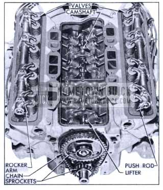
1953 Buick Valve Mechanism
The camshaft, is located in the angle of the cylinder block above the crankshaft where it is supported in five steel-backed, babbitt-lined bearings. It is driven from the crankshaft by sprockets and a single outside guide type chain. Thrust of the camshaft is taken on a plate mounted behind the sprocket, and proper end play is provided by a spacer between the sprocket and the cam shaft front bearing journal.
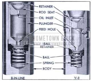
1953 Buick Hydraulic Valve Lifters
Hydraulic valve lifters and solid one-piece steel push rods are used to operate the overhead rocker arms and valves of both banks of cylinders from the single cam shaft. This system requires no lash adjustment at time of assembly or in service; therefore, the rocker arms do not have adjusting studs.
The hydraulic valve lifters are similar to the lifters used in the 8-in-line engines but are smaller in size and are fed with oil through galleries in the crankcase instead of through the push rods. Oil enters each lifter through grooves and feed holes in the lifter body and the plunger.
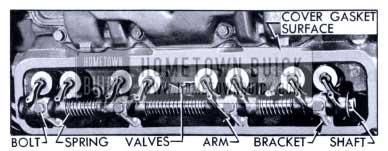
1953 Buick Rocker Arms and Valves
The eight rocker arms for each bank of cylinders are mounted on a tubular steel shaft supported on the cylinder head by four die cast brackets. The rocker arms are offset to accommodate the different planes of movement of the valves and the push rods which pass through the cylinder head to one side of the valves.
The valves operate vertically in guides pressed into the cylinder head and each valve has two concentric springs to insure positive seating throughout the operating speed range. Inlet valve heads are 1 3/4″ and exhaust valve heads are 1 1/4 in diameter. Valves and rocker arms are protected by a cover which seats against a raised horizontal surface on each cylinder head, and a cork gasket insures against oil leaks.
ENGINE LUBRICATION SYSTEM
1953 Buick Oil, Pump and Screen
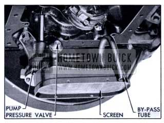
The helical geared oil pump is mounted on the lower side of the crankcase at the rear end, where it extends down into the oil sump. The pump shaft is coupled to the ignition distributor shaft, which is driven from the camshaft through spiral gears.
The pump inlet is equipped with a horizontal stationary screen of ample area. If the screen should become clogged for any reason, oil may be drawn into the pump through a vertical U-shaped tube which provides a bypass around the screen.
A spring-loaded valve regulates the pump output pressure to 35 pounds at 35 MPH under normal operation. Drilled passages in pump body and crankcase conduct all oil from the pump to the oil filter.
1953 Buick Oil Filter
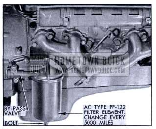
The AC full flow type oil filter is externally mounted on the right side of crankcase at the rear end. The filter contains a replaceable Aluvac filter element which permits rapid passage of oil with a minimum drop in pressure.
Normally, ALL engine oil passes through the filter element. If the element becomes restricted enough to produce 4 to 5pounds difference in pressure between the inlet and outlet ports of the filter, a spring-loaded ball type valve in the filter body will open to by-pass the element and route oil directly into the main oil gallery.
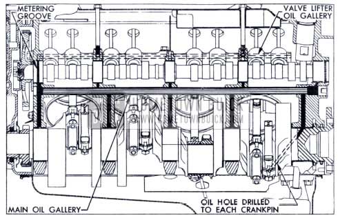
1953 Buick Oil Galleries
The main oil gallery, running full length of the crankcase in the angle below the camshaft, is formed by a steel tube cast in place. Through connecting passages drilled in the crankcase it distributes oil at full pres sure to all crankshaft and camshaft bearings.
Holes drilled in the crankshaft carry oil from the crank shaft bearings to the connecting rod bearings. Pistons and cylinder walls are lubricated by oil forced through a small notch in the bearing parting surface on connecting rod, which registers with the hole in crankpin once in every revolution. Piston pins are lubricated by splash.
Oil holes in the crankcase and camshaft front bearing align with a groove in the camshaft front bearing journal which meters the flow of oil from the main oil gallery to the valve lifter oil gallery in each bank of cylinders. The drilled oil gallery, running full length of each cylinder bank, cuts into the lower sides of all valve lifter guide holes to supply an adequate volume of low pressure oil to each hydraulic valve lifter. Oil enters each lifter through grooves and holes in the lifter body and the plunger.
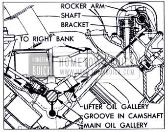
1953 Buick Oil Supply to Lifters, Rocker Arms and Valves
The rocker arms and valves on each cylinder head are supplied with low pressure oil from the valve lifter oil gallery through connecting passages drilled in the front end of cylinder block and head.
The oil passage in cylinder head ends in a counterbored recess surrounding the bolt which attaches the rocker arm shaft front bracket. The oversize bolt hole through the bracket permits oil to flow up into the hollow rocker arm shaft, which is plugged at both ends.
Each rocker arm receives oil through a hole in the shaft, and parallel grooves in the rocker arm assure proper lubrication of the bearing surface. Oil is metered to the push rod ball seat and to the valve stem through holes drilled in the rocker arm. Excess oil drains off and returns to the oil pan through passages in cylinder head and cylinder block.
ENGINE COOLING SYSTEM
The water pump uses the same type of packless seal and ball bearing shaft as in 8-in-line engines but is other wise new and more compact in design.
The inlet pipe cast on the pump cover feeds into the passage formed by the cover and the front face of the impeller, which is mounted on the bearing shaft with the vanes facing rearward. Coolant flows through the inlet passage to the low pressure area at the center, where it then flows rearward through six holes in the impeller.
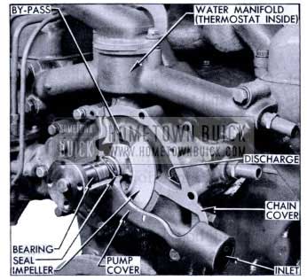
1953 Buick Water Pump Installation
Vanes on the rotating impeller cause the coolant to flow radially outward into two discharge passages cast in the timing chain cover, and these passages deliver an equal quantity of coolant to each cylinder bank water jacket.
Water jackets extend down below the lower limit of piston ring travel and the coolant completely surrounds each cylinder barrel to provide uniform cooling. After flowing upward through connecting passages the coolant leaves the cylinder heads through a water manifold that provides a common connection between both heads and the radiator.
The water manifold houses the radiator thermostat and provides the by-pass through which coolant returns to water pump when the engine is cold and thermostat is closed. A new “pellet” type thermostat, opening at 157 degrees – 162 degrees F. replaces the bellows type thermostat previously used. Since pressure does not affect the pellet type, it gives the same results with alcohol as the bellows type which opens at 151 degrees F.
CRANKCASE VENTILATION
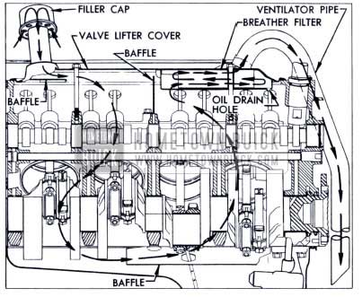
1953 Buick Crankcase Ventilation
Crankcase ventilation is provided by the ventilating type oil filler cap located at front end of the valve lifter cover and the crankcase ventilator pipe connected to the rear end of lifter cover. The filler cap contains a gauze filtering element to exclude dirt. A gauze filled breather filter is built into the rear end of the lifter cover to remove oil from the air stream before it leaves the crankcase.
The ventilator pipe extends down to near the bottom of engine so that air passing the open end will create suction when the car is moving forward. The middle trans verse web of the crankcase and a baffle mounted above it form a partition which causes the draft of air to be drawn downward through the front section of the crank case and upward through the rear section. As the air stream reverses direction in the filter, oil is separated and drained back through a hole in rear end of filter.
ENGINE FUEL SYSTEM
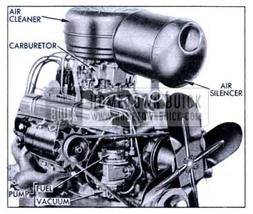
1953 Buick Fuel Pump, Carburetor, Air Cleaner and Silencer
The combination fuel and vacuum pump is mounted on the right side of the timing chain cover and is actuated by a hardened, chrome-plated, stamped steel eccentric mounted on front side of the camshaft sprocket. The fuel section is mounted above the vacuum section, has extra large valves, and has a built-in air dome with diaphragm to dampen out pulsations in the fuel stream. The pump construction is otherwise similar to the 1952 Series 40-50 pump.
A new inverted elbow type air cleaner and silencer is mounted lengthwise on top of the engine. Air enters the silencer first and then passes through the heavy duty ml bath air cleaner located directly above the carburetor . This location allows the mesh of the cleaner element to act as a flame arrester in case of backfire through the carburetor.
The 4-barrel carburetor (Carter or Stromberg) is similar to the unit used in 1952 except for slight modifications of external linkages and internal features. New calibrations of the metering, idling and venting systems are separately furnished in the tabulated specifications.
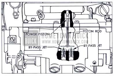
1953 Buick Stromberg Power System
The Stromberg choke piston has been modified to reduce the possibility of sticking due to dirt. To provide independent metering control for each primary barrel, a separate power by -pass jet has been installed in each barrel, instead of the single jet previously located in a passage connecting both barrels. Both by-pass jets are operated by a cross bar attached to the single power piston rod.
The Carter low speed jets and passages have been moved from the air horn to the main body, for manufacturing reasons.
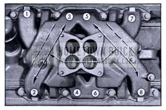
1953 Buick Intake Manifold Distribution
A low-restriction, dual (2 section) intake manifold is bolted to the inner edges of both cylinder heads, where it connects with all inlet ports. The carburetor feeds one primary and one secondary barrel into each section of the manifold. Each manifold section feeds four cylinders- two in each bank.
An important feature in the intake manifold design is that the end branches of each section run at 90 degrees to the connecting middle branch, thereby forming a T- junction at the dividing point. This T- junction dividing system assures a more uniform division and distribution of fuel to the cylinder inlets than can be attained with the “Y” type system commonly used on V-8 engines.
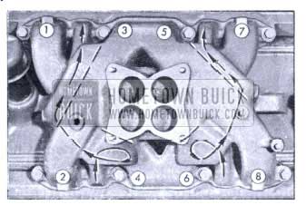
1953 Buick Intake Manifold Heat Chambers
The intake manifold is heated and hot spots are pro vided at the T-junction dividing points by crossover chambers cast along the outer walls of each end branch. These chambers connect to the two middle exhaust passages in each cylinder head.
A manifold heat control valve with a bi-metal thermostat is located in the left exhaust manifold. When the engine is cold and the thermostat closes the valve, the resulting back pressure in the manifold forces exhaust gas through the crossover chambers to the right exhaust manifold. As the engine warms up and the thermostat releases the valve, the flow of hot gas through the crossover chambers is reduced. Restricted openings in the metal intake manifold gaskets further reduce the flow of gases through the manifold when the engine is warm and the heat valve is open.
Hot spots located at the dividing junctions aid in vaporizing the heavier particles of fuel which are swept against the outer walls due to their greater momentum. The heated intake manifold also aids in obtaining a uniform fuel distribution.
Warmed air for operation of the automatic choke thermostat is supplied through an insulated pipe connected to the thermostat housing and to an alloy steel heating tube in the right exhaust manifold. The heat tube is mounted horizontally inside the manifold with the en trance end opening into a heating chamber located on the outside of manifold.
ENGINE EXHAUST SYSTEM
Each cylinder exhausts through an individual port into a separate branch of the exhaust manifold, which IS mounted on the outer side of each cylinder head. Use of individual exhaust ports instead of the customary “Siamese” type of porting permits valve timing that improves engine efficiency, minimizes exhaust valve burning, and effects more complete scavenging of exhaust gases from cylinders.
Both exhaust manifolds discharge into one front. exhaust pipe. This pipe crosses under the front of engine from the left manifold to meet with the right manifold in a “Y” joint that provides a common, low-restriction connection with the rear exhaust pipe attached to the muffler on right side of the frame.
The muffler is an oval-shaped, dynamic flow type having very low back pressure. It is double wrapped. of heavy gauge sheet steel with a layer of asbestos placed between wrappings to aid in reduction of noise transfer and prevents any “oil-canning” effect. The. muffler and exhaust pipes are supported by free hanging, rubber-fabric mountings which permit free movement but eliminate transfer of noise and vibration into the passenger compartment.
ENGINE ELECTRICAL UNITS
As compression pressure is increased, the secondary voltage required at the spark plugs is also increased. Secondary voltage higher than normal requirements must provided to insure freedom from misfiring under adverse conditions such as a cold engine, lean fuel mixture, dirty or improperly adjusted spark plugs.
The high compression pressure in the Buick V-8 engine demands secondary voltage that is very near the maximum obtainable with a 6-volt primary system. To insure adequate voltage for positive ignition the 12-volt primary system was adopted, and this is the primary reason for use of all 12-volt electrical equipment in models equipped with the V-8 engine.
Except for differences in operating, test and adjustment specifications due to the higher voltage, the 12-volt electrical units are basically the same as the 6-volt units used in cars equipped with the 8-in -line engine. The 12-volt test equipment and the specifications separately furnished in tabulated form must be used when servicing these units; otherwise, the procedures are the same as given for 6-volt equipment.
BATTERY
The Delco-Remy 12-volt battery is mounted on the left front fender skirt under the hood. The top is protected by a removable cover because the cell connector straps are exposed for better cooling.
The battery has 6 cells with 11 plates per cell, a capacity of 70 ampere-hours, and a rating of 840 watt-hours. The previously used 17 plate 6-volt battery had a rating of 720 watt-hours.
GENERATOR
The Delco-Remy 12-volt generator is mounted in the right exhaust manifold in position to be driven by the fan belt. It has a rated output of 30 amperes at 14.0 volts or 420 watts, compared with 360 watts for the 6-volt generator.
SPARK PLUGS
AC Type 44-5 spark plugs having 14 MM threads, short (3/8″) terminals, and gaps of .30″ – .035″ are specified for the V-8 engine. Rubber boots cover the cable terminals at the spark plugs.
The type 55-5 spark plug is not interchangeable with the Type 46-X plug specified for the 8-in-line engine because of the difference in heat range. The Type 44-5 plug is too cold for the 8-in-line engine.
IGNITION COIL, DISTRIBUTOR, AND RESISTOR
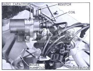
1953 Buick Coil, Distributor and Resistor
The Delco-Remy oil filled ignition coil is mounted on the rear end of the intake manifold. The Delco-Remy ignition distributor is mounted in the top rear end of the crankcase in position to be driven by the camshaft through spiral gears.
A new feature is a resistor, mounted on a bracket beside the coil which is connected in series between the ignition switch and the positive (+) terminal of the coil. The resistor limits to a safe maximum the primary current flow through the coil and the distributor contact points.
Action of the resistor protects the contact points during slow speed operation when they are closed for longer intervals. It also protects against excessive built up of primary current when the ignition switch is closed with engine stopped and contact points closed.
A new terminal on the cranking motor solenoid switch is connected to the ignition coil so that the resistor is by passed during cranking operation. Elimination of the resistor overcomes the effects of reduced voltage due to the cranking motor drain on the battery.
The 12-volt ignition distributor is slightly larger than the 6-volt unit and is designed for CLOCKWISE rotation. The cam is shaped to open and close the contact points faster, to give a longer dwell or closed period in which to build up the primary field in the coil. Contact point opening remains at .0125″ to .0175″.
The distributor upper bearing is provided with a reservoir and external fitting for lubrication with engine oil instead of the chassis lubricant used with the 6-volt unit.
TIMING MARK AND POINTER
Spark timing is set with No. 1 piston at 5 degrees b ore upper dead center. This position exists when the yellow mark on the top edge of one flywheel ring gear tooth is aligned with the pointer located inside the sight hole in left side of the flywheel housing.
A figure “5” is stamped in the front end of the marked gear tooth for identification in case the yellow mark becomes obscured. There is no U.D.C. mark on the V-8 flywheel.
NEUTRAL SAFETY SWITCH
A new combination neutral safety and back-up lamp switch is used with the V-8 engine. It is mounted on the steering column jacket under the cowl and is actuated by the transmission control shaft.
Slotted screw holes permit sidewise movement of the switch for timing adjustment. The correct cut-in point for the cranking circuit is 1/8″ to 3/16″ out of Neutral toward Drive range, using adjustment procedure given in Paragraph 10-34, b of the 1952 Shop Manual. No adjustment is required for the back-up lamp circuit.
Leave A Comment
You must be logged in to post a comment.