STRAIGHT-EIGHT ENGINE CYLINDER HEAD
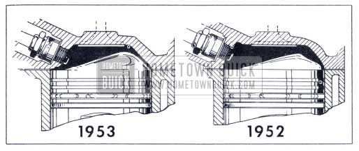
1953 Buick F-263 Engine Combustion Chamber
The cylinder head used with the “F-263″ Straight Eight engine has been redesigned to improve power and economy. Increased compression ratios have been made possible, without adversely affecting detonation characteristics, by changing combustion chamber and piston head shapes to compress the fuel charge into a more compact area. Modification of the combustion chamber shape also permits relocation of the spark plug in a position 5/16” nearer the center of the chamber with a resultant decrease in flame travel.
As in 1952, only one cylinder head will be used on the “F-263″ engine with compression ratio variations accomplished through use of different cylinder head gasket thickness, as follows:
7.0 compression ratio – .075″ gasket
7.6 compression ratio – .015” gasket
CRANKSHAFT
The counterbore in the rear end of the crankshaft has been dimensionally changed to accommodate the new Twin-Turbine Dynaflow pump cover. As a result, the Dynaflow crankshaft cannot be used interchangeably with past model “F-263” engines.
ENGINE FAN SHROUD
For better engine cooling characteristics a shroud is now mounted just behind the radiator. This controls the flow of air through the 4 bladed fan and prevents air from circling back around the outside of the blade tips. By eliminating recirculation of air the shroud improves the idling and low speed cooling without affecting the high speed cooling efficiency.
The shroud is removed by disconnecting the upper radiator hose from the radiator, removing the fan and water pump pulley and removing the six bolts that attach the shroud to the radiator frame.
Should the radiator require removal, it is necessary to disconnect the upper and lower radiator hoses, remove the six bolts securing the shroud to the radiator frame, move the shroud back an inch or two for clearance, arid disconnect the radiator from its supports.
REAR AXLE
AXLE RATIOS
Optional rear axle ratios are not available on 1953 models, other than export cars. Standard ratios are as follows:
Series Ratio
40 Synchromesh 3.9
40 Dynaflow 3.6
50 Synchromesh 3.6
50 Dynaflow 3.6
70 Dynaflow 3.6
FRONT PROPELLER SHAFT OIL SEAL
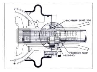
1953 Buick Propeller Shaft Seal
A new type seal will be used in the front of the torque tube to seal the rear end of the transmission on all 1953 cars. This design eliminates the present universal joint oil seal and propeller shaft spline seal. The new seal fits tight in the torque tube front flange with the lip edge to the front of the car, and rides on a sleeve which is pressed on the shaft stub. The sleeve closes off the spline. The seal also acts as the pilot between the torque tube and torque ball. The old cork gasket for the flange joint is replaced by a paper flange gasket. The installation of the seal can be made easily with hand tools.
Caution is necessary to prevent damage to the oil seal caused by permitting sharp impacts or heavy sideways pressure on the propeller shaft stub which may crush the seal or cause it to pop out of place. Such forces are also very damaging to the propeller shaft straightness and balance.
The pinion and propeller shaft assembly may be removed and replaced in service without disconnecting the axle from the torque ball. Care must be taken when installing the shaft, with the axle in the car, to start the propeller shaft stub in through the seal gently. Striking the seal hard with the propeller shaft end will damage the seal retainer causing a leak. Once the shaft is properly centered in the third member, the remainder of installation is as before. It is definitely recommended that the pinion be pressed in rather than driven in with a drift. This can be done by means of a screw or jack pushing from a bar fastened securely across the carrier pedestals. Many hydraulic jack cylinders are adaptable to such a method which is easier, safer, and better for the parts than pounding with a drift. For pinion removal, pullers may be used if they can be adjusted to fit well on the pinion and pull straight without chipping teeth.
The new parts resulting from this change are:
Universal Joint – Shorter rear yoke
Torque Ball – Longer neck to flange, 4 holes
Boot – Larger
Propeller Shaft – Longer stub with sleeve, shorter tube
Torque Tube – Shorter tube, heavy front flange, four bolt holes
Oil Seal – New part
Gasket – New part
CHASSIS SUSPENSION FRONT END SUSPENSION
Steering knuckle support angles on all 1953 Series have been changed to provide zero degrees caster at curb weight. This change is also scheduled for late 1952 production.
Zero caster reduces the tendency of the wheels to shimmy due to irregular tire wear, and provides a reduction in steering effort.
Caster adjustment is made in the same manner as with former models.
Series 50 and 70 front tread is 60″, representing a 1″ increase over comparable 1952 Series.
CHASSIS SPRINGS
Chassis springs used on all Serie70 models have been lightened for use with the lighter engine and car. In view of comparable Series 50 and 70 car weights, spring equipment is identical.
Series 40 front spring rates are revised to provide better all-around balance.
SHOCK ABSORBERS
Shock absorber calibrations on all Series cars are changed to coincide with frame changes that alter ride and hand ling characteristics.
STEERING GEAR POWER STEERING
Power steering is optional, at extra cost, on all 1953 Series. The gear ratio is 21.3, same as 1952 Series 50 and 70 power steering. All Series gears have the integral pump and reservoir construction featured on the 1952 Series 50 gear.
MANUAL STEERING
Steering effort when turning corners and parking has been reduced through use of a 23.6 gear ratio on all Series. This is the ratio formerly used on Series 70 cars only.
BRAKES
The brakes and drums on the Series 40 cars will be identical to those on the 1952 Series 40 and 50 cars.
Rear brakes and drums on Series 50 cars will be increased in width from 1 3/4″ to 2 1/4″. Front drums and linings remain the same (2 1/4″) as used in 1952.
New secondary linings will be used on the Series 70 cars. They are identified by an orange paint mark on the side of the lining. The drums are the same as those previously used. The geometry change which was incorporated in late 1952 cars will also be used. This change consisted of raising the adjusting screws 23/64″ toward the center of the backing plate and lowering the anchor pin 3/16″ toward the center of the backing plate. By doing this the self -energizing action of the shoes is increased providing less pedal effort. This modification does not change the procedure for adjusting the shoe clearance.
FRAME SERIES 40
Stock thickness in Series 40 frame side rails has been increased to .102″, same as 1952 Series 50 frames. This change is accompanied by a reduction in front and rear frame extension thickness and elimination of box section reinforcements in the side rails at the dash line.
Body brackets and bolts have been added at the No. 4 location, slightly forward of the center pillar on 4 door Models, to improve side rail jacking and eliminate the possibility of structural weakness under unusual driving conditions.
SERIES 50-70
The shear plate added to 1952 Series 70 frames, between the front frame extension and side rail at the No. 2 body bracket location, is carried-over into 1953 and also added to Series 50 frames. Body brackets and bolts are added to Model 76R at the No. 4 location.
These changes provide uniform body mounting on all Series cars except that Series 50 and 70 jobs have an inner bolt (in rail) at the No. 6 location, which is for- ward of the rear end side rail kick-up.
ELECTRICAL SYSTEMS
12 VOLT SYSTEM
Electrical components of the 12 volt system are similar in design and operation to 6 volt units. Service procedures are the same except that new calibrations and test figures are required, and 12 volt test equipment is essential. It should also be stressed that 6 and 12 volt units are not interchangeable under any conditions.
Chassis and body wiring circuits for the 12 volt system are unchanged from 6 volt procedure except that 12 volt lamps draw less current and a reduction in wire size has been possible in some circuits.
RADIO AND ACCESSORIES
Sonomatic and Selectronic radios are optional, at extra cost, on all 1953 Series. Separate models are used for 6 and 12 volt operation and they cannot be interchanged.
A feature of 1953 radios is the use of miniature tubes for all purposes with the exception of output and rectifier tubes.
DEFROSTER
Defroster units in Series 50 and 70 cars have been redesigned along Series 40 lines to permit introduction of heated outside air at the lower level on the front seat passenger side. All Series cars use the same defroster inlet housing as used on the 1952 Series 40, but, the Series 50-70 outlet housing will have a different valve arrangement. The defroster air manifold under the instrument panel is retained on Series 50-70 models while Series 40 cars will continue to use individual defroster nozzles.
HEATER AND DEFROSTER HOSE CIRCUITS
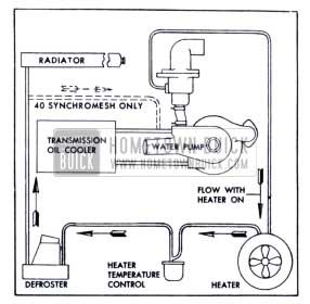
1953 Buick Heater and Defroster Water Flow
Heater, defroster and Dynaflow oil cooler hose circuits have been revised to separate the cooler entirely from the heating system. This results in higher heater and defroster temperatures, particularly during very cold weather.
Hose connections on all Series cars are the same except the Series 40 Synchromesh, in which the water return from the defroster core is to the suction side of the water pump instead of to the bottom of the radiator.
ENGINE HOOD – ALL SERIES
1953 Buick Hood Mounting Pin
A new alligator type hood will be used on all 1953 Models.
This hood will give more room in the engine compartment will be easier to lift, requires no separate braces to keep open and is designed for easier adjustment in fitting to adjacent members.
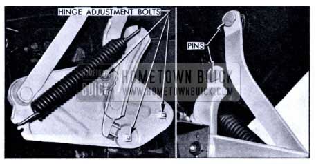
The rear of the hood is mounted through linkage by two brackets – each of these brackets being secured to the body by three bolts.
The brackets may be moved vertically and horizontally for any desired adjustment.
Two pins secure the rear corners of the hood to the linkage. When the hood is in the open position, removal of these pins will disconnect hood from the body.
The hood is held open in any position by two hinge springs located at the rear corners of the hood and operating in conjunction with the linkage and brackets.
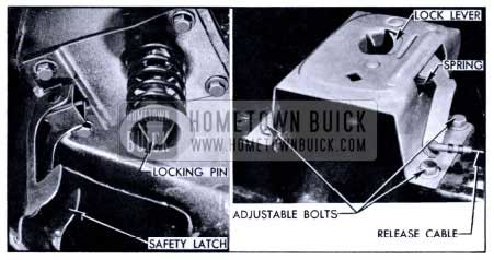
1953 Buick Hook Locking Pin
The front of the hood is secured in place by a single spring loaded pin which is bolted to the hood. This pin mates with a latch which is bolted to a rigid cross member in front of the radiator. The pin is threaded and may be moved up or down for proper tension and positioning. The latch may also be adjusted to mate with the pin.
The hood is opened by pulling a knob located at the lower left side of the instrument panel.
This knob actuates the front lock (through a cable) which raises the hood into the “safety lock” position.
1953 Buick Hood Guide
1953 Buick Hood Guide Plate
The safety latch is released at the front hood lock by lifting a spring loaded lever.
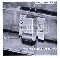
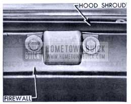
A roller guide is used on the rear center underside of the hood to give clearance as it is raised over the cowl and lower windshield reveal moulding. This guide is also adjustable to obtain proper position with a plate upon which the roller runs: – the plate is bolted to the firewall.
VENTILATOR AIR DUCTS (V-8 ENGINES ONLY)
In order to allow more room in the engine compartment the front section of the ventilator air ducts will be fabricated as an integral part of the fender skirt. This new method of routing in fresh air will also improve temperatures in the car during Summer weather and lessen engine noises heard by the driver and passengers.
The use of round flex tubing to connect the duct in the skirt to the firewall will continue to be used.
From a service standpoint there are no adjustments necessary.
Leave A Comment
You must be logged in to post a comment.