SECTION A – 1958 BUICK FLIGHT PITCH DYNAFLOW SPECIFICATIONS
DESCRIPTION AND OPERATION
1-FLIGHT PITCH DYNAFLOW TRANSMISSION IDENTIFICATION NUMBER
A production identification number is stamped on the lower side of the transmission case directly forward of the left front corner of the oil pan. The identification number consists of a letter followed by a number containing one or more digits.
Since the production identification number furnishes the key to construction and interchangeability of parts in each transmission, the number should be used when selecting replacement parts as listed in the master parts list. The number should always be furnished on Product Reports,
AFA Forms, and correspondence with the factory concerning a particular transmission.
2-FLIGHT PITCH DYNAFLOW GENERAL SPECIFICATIONS
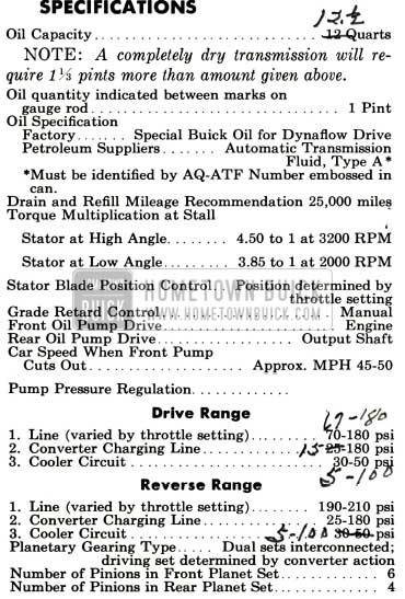
1958 Buick Flight Pitch Dynaflow Specifications
3-FLIGHT PITCH DYNAFLOW TIGHTENING SPECIFICATIONS
Use a reliable torque wrench to tighten the attaching bolts or nuts of the parts listed below.
NOTE: These specifications are for clean and lightly lubricated threads only. Dry or dirty threads produce increased friction which prevents accurate measurement of tightness.
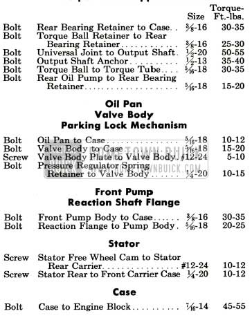
1958 Buick Flight Pitch Dynaflow Tightening Specifications
4-FLIGHT PITCH DYNAFLOW MANUAL CONTROL MECHANISM AND OPERATING CONTROLS
Manual Control Mechanism
The Flight Pitch Dynaflow provides five different control or operating ranges which may be manually selected by the driver through movement of the shift control lever at top of steering column. A pointer on the control lever and a dial located on the instrument panel aid in locating the lever for each range. Letters on the dial, reading from left to right identify each range as follows:
- P=Parking
- R=Reverse
- N =Neutral
- D=Drive
- G =Grade Retard
The control lever can be moved m the same plane from Drive “D” to Neutral “N” by overcoming detent resistance. To shift lever to Parking “P”, Grade Retard “G” or Reverse “R” it is necessary to raise the lever against spring pressure. The control lever actuates a shaft housed in the steering column which is connected by levers and rods to a shift control valve in the transmission. The control shaft also operates a neutral safety switch in the starter motor circuit which does not allow the starter to be energized with the transmission in any range other than Parking “P” or Neutral “N” position.
Parking “P” Range
Parking range is to be used in conjunction with the step-on parking brake to prevent possibility of car motion. The shift control lever must be raised when shifting into or out of Parking range.
Parking range must never be entered when the car is in motion or serious damage to the transmission may result.
Parking range should always be used when it is desirable to run and accelerate the engine without possibility of car movement, as when working in the shop.
When in Parking range a parking lock ratchet wheel on transmission output shaft is engaged by a locking pawl mounted in rear of transmission case, providing a positive mechanical lock for the rear wheels.
The locking pawl is actuated by the transmission control linkage through a system of rollers and apply spring which hold the pawl solidly against the ratchet wheel until engagement is accomplished. If the pawl does not engage the ratchet wheel when first applied it will snap into place as the wheel turns if the car moves slightly. See figure 1.
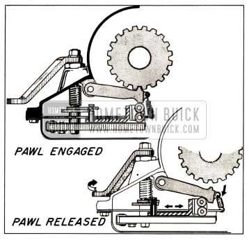
1958 Buick Parking Lock Mechanism
The engine may be started while the shift lever is in Parking “P” position.
Neutral “N” Range
Neutral range may be used when it is desirable to operate the engine without car motion. Should it ever become necessary to push a Dynaflow equipped car to start it, Neutral range should be used until the car has reached sufficient speed to crank the engine in Grade Retard “G” range. The starter may be used to crank the engine in Neutral “N” range.
Drive “D” Range
Drive range is used for all normal driving except when it is desirable to slow the car on descending grades as specified for Grade Retard “G” range.
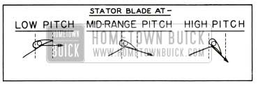
During part throttle operation and light acceleration the Flight Pitch stator blades are in low angle or “cruise” position. When extraordinary acceleration is required the blades are automatically positioned at a higher angle as the accelerator pedal is depressed beyond the half throttle position. The stator blade position is infinitely variable; the blades being positioned at maximum high angle “performance” position as wide open throttle is reached.
Grade Retard “G” Range
Grade Retard range is used when additional engine braking is desired to descend hills or grades safely.
With selector lever in Grade Retard “G” range, a hydraulic piston engages a multiple disc clutch housed in the rear of the transmission case which acts on the torque converter components to drive the engine at a greater speed, thereby slowing the car. Light throttle pressure can be used to reduce the effectiveness of the retarder, however, the car should not be accelerated in Grade Retard “G” range. Grade Retard “G” range should not be entered at car speeds above 45 MPH.
Reverse “R” Range
Reverse range is used to move the car to the rear. The shift control lever must be raised slightly to shift into Reverse range.
Rocking Car Between Drive and Reverse
When the car is stuck in deep snow or mud it can be driven out by “rocking” the car back and forth alternately using Drive and Reverse until sufficient momentum is obtained to move car out in desired direction.
After accelerating engine slightly to provide sufficient power, hold shift lever up and move back and forth between Drive and Reverse. Control engine speed and time the movement of control lever so that the rear wheels push firmly against the snow or mud in each direction, but avoid spinning wheels.
Pushing Car to Start Engine
If it becomes necessary to push a Dynaflow equipped car to start engine, place shift control lever in Neutral until car speed reaches approximately 30 MPH. Then shift into Grade Retard “G” range. Increase car speed until engine cranks. After engine starts, return control lever to Neutral for warm-up. It is safer to push car than to tow it.
Towing Disabled Dynaflow Drive Car
A disabled Dynaflow Drive car must not be towed on rear wheels with transmission in any range other than Neutral, because unnecessary damage to transmission may result. It may be safely towed in Neutral (N) only, and towing speed should not exceed 35 m.p.h.
5-PRINCIPAL SECTIONS OF THE FLIGHT PITCH DYNAFLOW TRANSMISSION
To simplify description of construction and operation of the Flight Pitch Dynaflow, it will be divided into the following sections as shown in Figure 2.
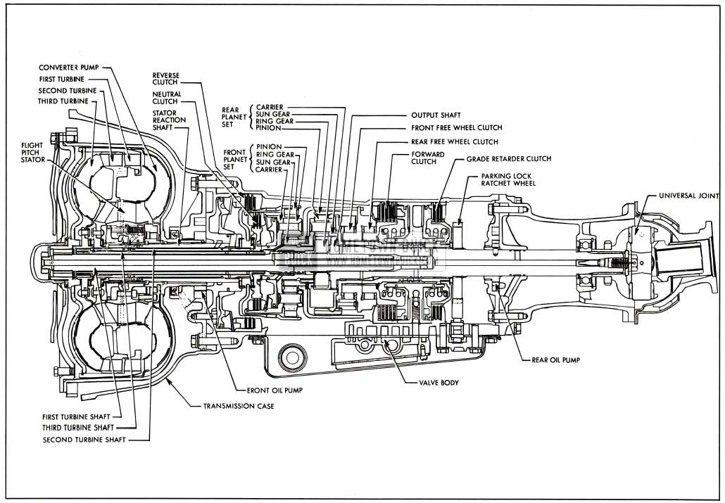
1958 Buick Side Sectional View of Flight Pitch Dynaflow Transmission
Transmission Case
The transmission assembly is bolted to the engine crankcase through the converter housing section of the transmission case. The transmission case and converter housing are one integral cast aluminum part.
Torque Converter and Planetary Gear Sets
The torque converter is coupled to the engine and hydraulically transmits engine torque through two connected planetary gear sets to drive the car. The torque converter automatically provides torque multiplication to meet varying driving conditions. Construction and operation of the torque converter are described in Paragraph 6.
Hydraulic Controls
The hydraulic control system includes devices for controlling forward clutch, reverse clutch, neutral clutch, Flight Pitch stator, and grade retard clutch. The hydraulic system also provides for filling the torque converter and circulation of oil for lubrication and cooling.
Oil pressure is provided by two pumps, one mounted just rearward of the torque converter and driven at engine speed by lugs on converter pump housing hub. The other is located at the forward end of the rear bearing retainer and is driven by the output shaft. The units which regulate oil pressure, govern engagement of forward or reverse clutch, and application of grade retarder, are contained in a valve body mounted on the bottom of the transmission and enclosed by the oil pan. Construction and operation of all hydraulic control units are described in Paragraph 8.
Grade Retarder
A hydraulically operated multiple disc clutch housed at the rear of the transmission case, when engaged, causes the output shaft to turn the first turbine at an accelerated rate thus overdriving the engine. The grade retard clutch is engaged as the selector lever is moved to Grade Retard “G” range. The car should not be accelerated in Grade Retard “G” range. Construction and operation of grade retarder is described in Paragraph 7.
Rear Bearing Retainer and Torque Ball
The rear bearing retainer is bolted to the rear end of the transmission case and the torque ball is assembled on the rear of the retainer. The rear bearing retainer houses the rear oil pump, output shaft rear bearing, and speedometer drive gear.
6-FLIGHT PITCH DYNAFLOW TORQUE CONVERTER
The Dynaflow torque converter is connected to the engine flywheel and serves as a drive through which engine torque (turning force) is transmitted to move the car. The torque converter “steps up” or multiplies the engine output torque whenever car operating conditions demand greater torque than the engine can supply. In this respect it serves the same purpose as the selective reduction gears used in other types of automotive transmissions.
Torque multiplication is always required when a car is started or accelerated at low speeds. Torque multiplication may be required when car is ascending steep grades, moving in deep snow, sand, etc. Torque requirements decrease as the car gains momentum, and when a point is reached where engine torque is adequate, no torque multiplication is required. From this point, the converter functions as an efficient fluid coupling, providing maximum economy.
The Dynaflow torque converter automatically provides the proper ratio of torque multiplication to meet the varying demands imposed by starting and driving under all ordinary driving conditions of load and grade. The transition through the various ratios or torque multiplication is smooth and devoid of steps or change points, since it is accomplished without the use of selective gears or controlled shifts.
The principle elements of the Flight Pitch torque converter are described in sub. paragraphs a, b, and c, and the operation of these units is described in sub. paragraph d.
Converter Pump
The converter pump is bolted to the engine flywheel so it rotates whenever the engine is running. The converter pump and its cover comprise a housing for all converter components. See Figure 2. The converter pump assembly consists of an inner shell, an outer shell and thirty vanes, all welded solidly to the converter pump housing.
The pump operates as a centrifugal pump, picking up oil at its center and discharging the oil at its rim, however, the shell of the pump is shaped to discharge the oil parallel to its axis in the form of a spinning hollow cylinder. The function of the pump is to convert engine torque into an energy transmitting flow of oil to drive the converter turbines, into which the oil is projected.
Triple Turbine Assembly
The Triple Turbine assembly is connected by coaxial shafts to the transmission output shaft through a neutral clutch and two planetary gear sets; the planet gear carriers of which are coupled together to act as a common carrier, a part of the transmission output shaft.
The Triple Turbine assembly consists of:
- A first turbine, first turbine disc and hub assembly, first turbine shaft and rear planet set sun gear. See Figure 3.
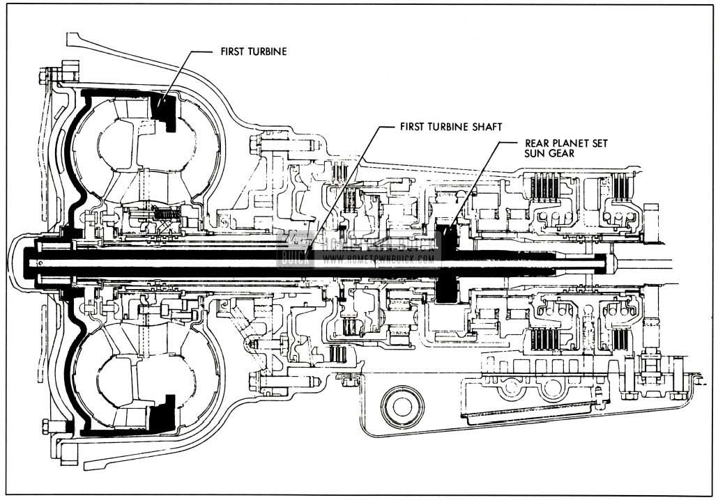
1958 Buick First Turbine, First Turbine Shaft and Rear Planet Set Sun Gear
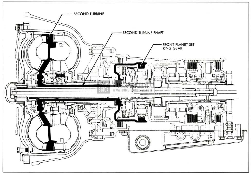
1958 Buick Second Turbine, Second Turbine Shaft, Front Planet Set Ring Gear and Reverse Clutch
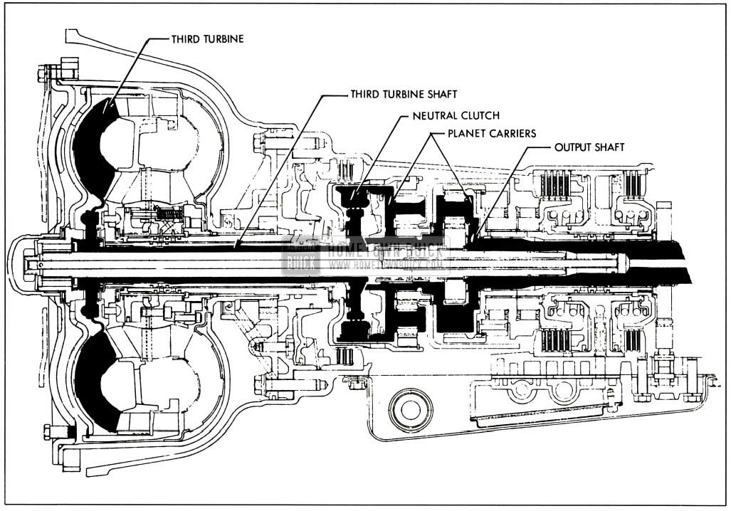
1958 Buick Third Turbine, Third Turbine Shaft, Neutral Clutch Planet Carriers, and Output Shaft
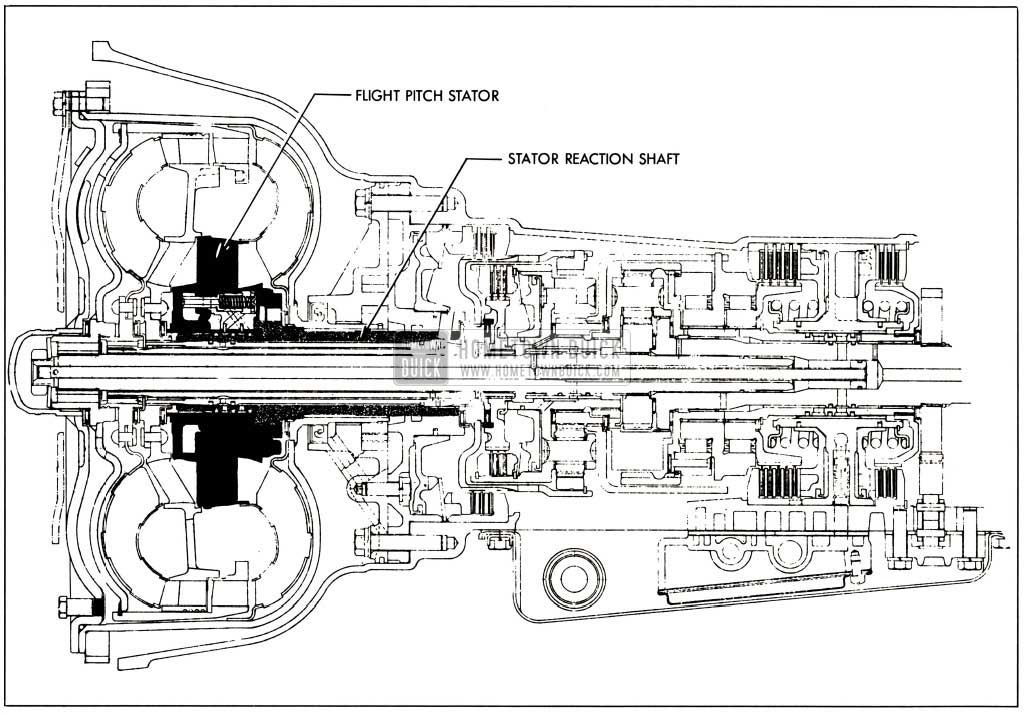
1958 Buick Flight Pitch Stator, Reaction Shaft and Free Wheel Clutch
Each turbine is independently connected to a member of the planetary gear sets, thus gear reduction in the planetary train is determined by relative motion of the turbines. The first turbine has a narrow set of vanes located at the pump exit in position to receive the spinning cylinder of oil projected from the pump. The first turbine is connected to its shaft and rear planet set sun gear by a disc and hub assembly supported on bronze bushings. The second turbine also has a narrow set of vanes positioned to receive oil after it has passed through the first turbine. The second turbine is riveted to a hub and shaft assembly which is supported on bronze bushings and splined to the front planet set ring gear and internally splined plates of the reverse clutch assembly. The third turbine has a broad set of vanes positioned at the second turbine exit and curved to direct the oil back into the Flight Pitch stator in a direction opposite converter pump rotation. The third turbine is riveted to a hub and shaft assembly which, when the neutral clutch is engaged, is solidly connected to the planetary gear carriers and the output shaft. Thus the third turbine, planet carriers and output shaft are an integral unit and turn together at the same rate of speed when the neutral clutch is engaged.
The function of the turbine and planetary gear system is to absorb energy from the oil projected by the pump and convert the energy to torque, the need for which is determined by driver demands and driving conditions.
Flight Pitch Stator
The Flight Pitch stator is located between the third turbine exit and the converter pump entrance. It is mounted on a reaction shaft and is equipped with a free wheel clutch. This clutch allows the stator to turn freely when torque multiplication is not required.
For normal “cruising” operation, the stator blades are set at a low angle relative to the centerline of the converter. Increased torque for acceleration may be obtained by greater throttle opening which accelerates the engine and simultaneously sets the stator blades at a higher angle.
Each of the twenty stator blades is mounted on an individual control crank supported at its outer end by a carrier ring and free to turn in its bearing in the stator blade carrier. The carrier houses a piston which controls the angle of all blades through the control cranks when oil pressure on either or both sides causes the piston to reposition itself as explained in sub. par. d, below.
The function of the stator, when stationary, is to alter the direction of oil flow from third turbine so oil enters converter pump spinning in same direction as pump rotation.
Operation of Torque Converter and Planetary Gear Sets In Forward Range
Description of torque converter operation will begin with the car stationary, transmission in Drive range and engine running at idling speed. The neutral and forward clutches are thus engaged, the converter pump is turning with the engine, and turbine members are stationary.
The engine driven converter pump projects a rotating cylinder of oil into the first turbine, the vanes of which are curved in such a manner that the oil leaving them is directed into the second turbine at a slight angle opposite pump rotation. The vanes of the second turbine are curved at a greater angle than those of the first turbine enabling the second turbine to absorb energy remaining in the oil after passing the first turbine. Oil is discharged from the second turbine into the third turbine and then into the Flight Pitch stator. As oil emerges from the third turbine near its center, the backward curvature of the exit ends of the third turbine causes the oil to spin opposite pump rotation as it enters the Flight Pitch stator. Oil thus striking the forward face of the stator blades causes its free wheel clutch to lock and hold the stator stationary. The stator blades then redirect the oil into the pump in the same direction as pump rotation.
At idling speed the force of oil flow against the turbine vanes is not sufficient to cause motion and oil flows from the pump through the first, second and third turbines, then into the Flight Pitch stator and back to the pump without transmitting any appreciable amount of torque.
When the throttle is opened the engine speeds up and with increased speed the pump projects a large volume of oil into the turbines at high rotary speed. This spinning cylinder of oil is similar to a flywheel in that it has stored energy (torque) which will be transferred to any object opposing its motion. Since the vanes of the turbines oppose the spinning flywheel of oil projected from the pump, the stored energy exerts a powerful impulsion force against the vanes, tending to rotate the turbines in the same direction as the pump. At this point the impulsion force of the oil is not sufficient to move the turbines. The oil flows through the turbine channels and into the stator, spinning at high speed in a reversed direction. It exerts a powerful reaction force against the stator vanes tending to rotate it opposite pump rotation. The stator is prevented from turning opposite pump rotation by its “free wheel” clutch.
(A reaction (rearward force) is exerted by a fluid changing direction or being accelerated. It is reaction force which tends to kick back the nozzle of a firehose when a stream of water emerges under pressure.)
Engine torque applied to the converter pump generates a given amount of energy in the oil projected from the pump against the turbine vanes When the turbines are stationary, the oil passes through the turbines and stator and returns to the pump with almost as much energy as when projected. The amount of energy in the oil thereafter projected from the pump, becomes the sum of the energy in the returning oil plus the energy resulting from engine torque application, or almost double the amount of energy that could be generated by engine torque alone. The greatly increased energy in the spinning flywheel of oil then projected into the turbines produces a corresponding increase in the impulsion and reaction forces acting on the turbine vanes.
The described buildup of forces produces a turning force or torque upon the turbine vanes which is much greater than the torque produced by the engine, therefore torque multiplication is accomplished. It would seem the torque multiplication would increase indefinitely as the cycle repeats itself, but mechanical factors limit the increase of torque multiplication beyond a definite ratio in any given torque converter design.
The buildup of forces against the turbine vanes causes the first turbine to turn in the same direction as the converter pump. The first turbine absorbs part of the energy transmitted by the oil stream and converts it into torque, which is imparted to the rear planet set sun gear, causing its planet pinions to turn and “walk” around the rear planet set ring gear, held stationary by a free wheel clutch. Thus, turning force is applied to the planet pinion carrier through the planet pinion shafts. The planet pinion carriers, the third turbine neutral disc clutch and output shaft are splined together and turn as a unit to drive the car. The ratio of the first turbine to the output shaft is 2.86 to 1. See Figure 7.
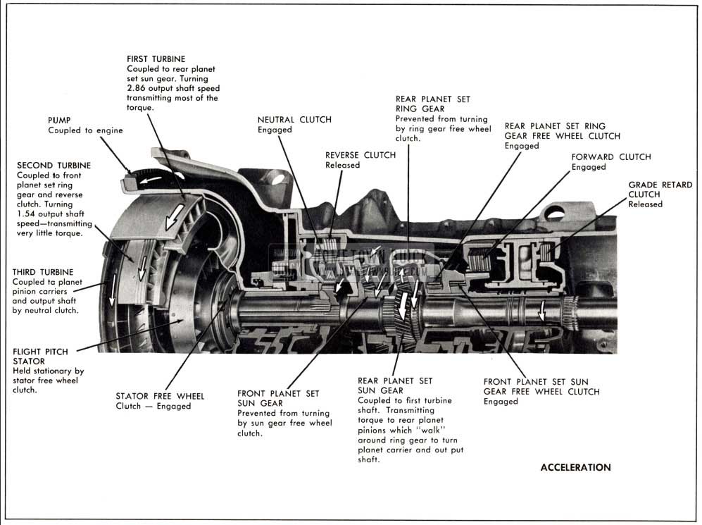
1958 Buick Operation of Components on Acceleration
In this manner the first turbine provides torque at high multiplication to drive the car at very low speeds. During low speed operation the first turbine transmits nearly all the torque to drive the car. As car speed increases more and more energy remains in the oil as it is emitted from the first turbine into the second turbine vanes. This energy is then absorbed and converted to torque which is transmitted to the front planet set ring gear, causing its planet pinions to turn and “walk” around the front sun gear held stationary by a “free wheel” clutch. See Figure 8.
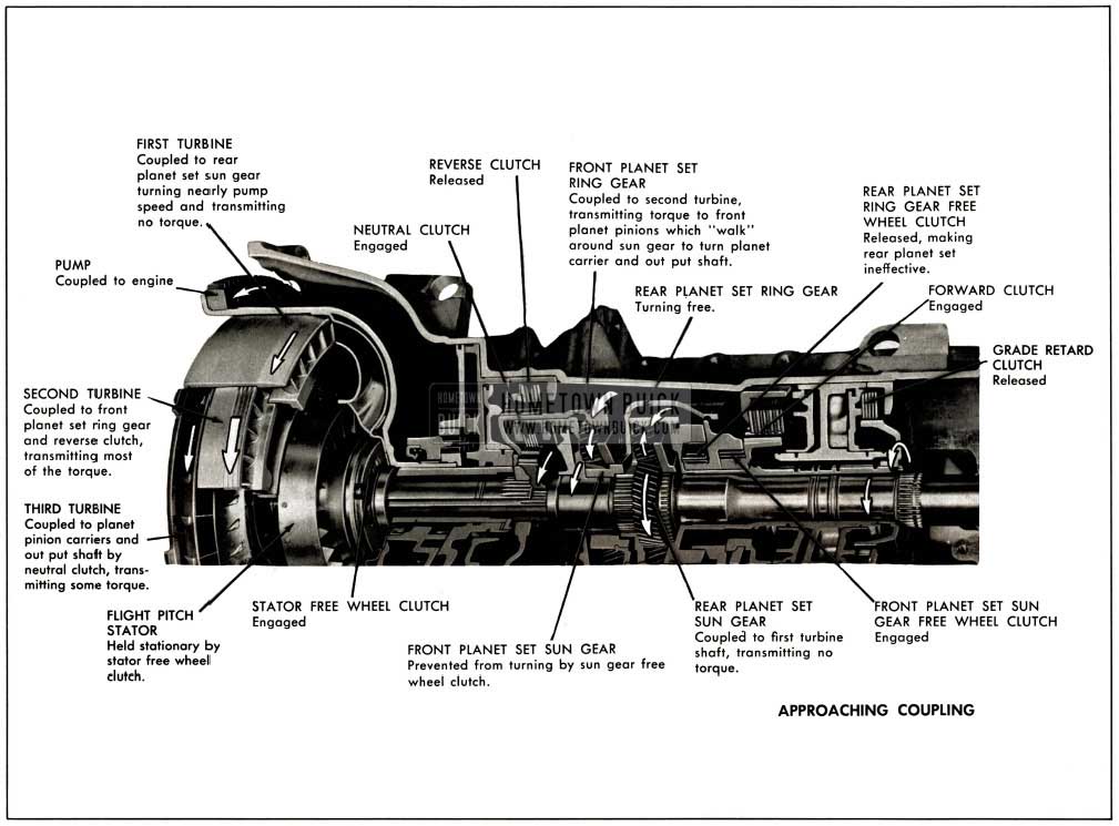
1958 Buick Operation of Components Approaching Coupling
In this manner the second turbine applies force to the front planet carrier which is splined to the rear planet carrier, and it to the output shaft. The ratio of the second turbine to output shaft is 1.54 to 1. Accordingly, at low car speeds both first and second turbines multiply engine torque which is further multiplied by the planet sets to accelerate and drive the car. As car speed increases, the second turbine supplies a greater percentage of driving torque and the first turbine less, until first turbine approaches a speed at which the width and curvature of first turbine vanes do not allow it to absorb energy from oil projected from the pump. The first turbine then “free wheels” turning free in the oil stream offering virtually no resistance to the oil flow from pump to second turbine. As the first turbine no longer transmits torque to rear planet set sun gear, the ring gear “free wheel” clutch is released, thus neutralizing the rear planet gear set. The rear planet set sun gear, planet carrier and ring gear then turn as a unit with the output shaft.
At this point the second turbine is transmitting a greater percentage of engine torque than the third turbine, but as engine and car speed increase, the angle at which oil is emitted from second turbine changes, striking vanes of third turbine at greater angle to axis of converter. The third turbine then transmits a greater percentage of engine torque and the second turbine less, until second turbine approaches a speed at which the width and shape of its vanes allow the second turbine to transmit no more torque to the front planet set ring gear. This action releases front planet set sun gear “free wheel” clutch. The front planet set ring gear, carrier and sun gear then turn as a unit with the output shaft. Accordingly, the second turbine free wheels allowing unimpeded oil flow from pump to third turbine.
The third turbine is now transmitting all engine torque to output shaft. See Figure 9.
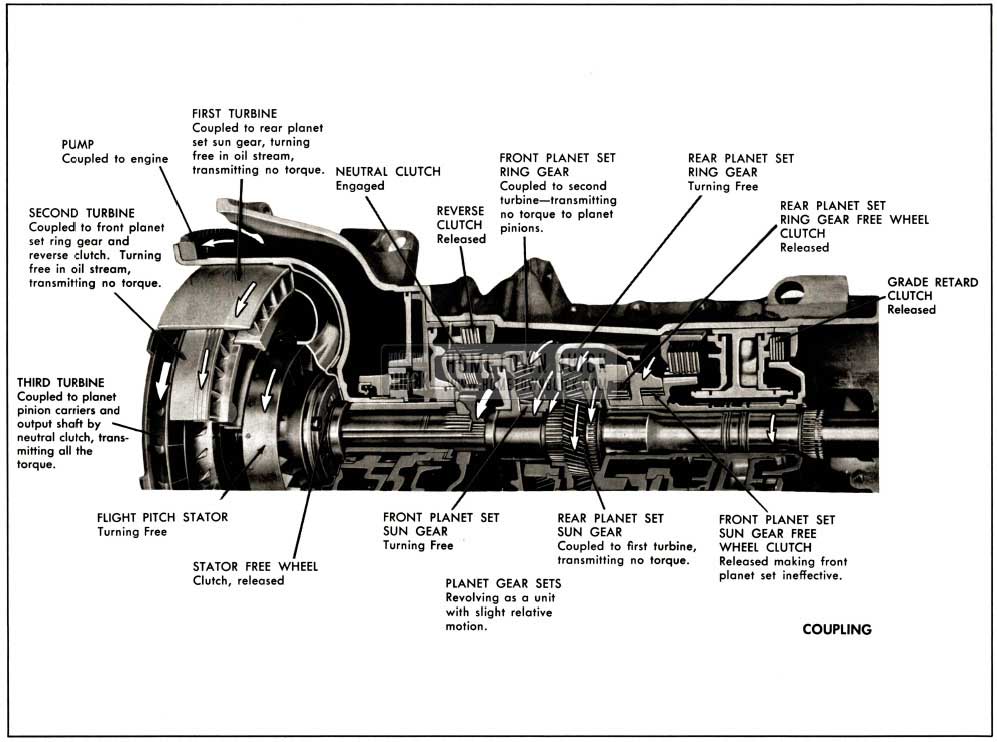
1958 Buick Operation of Components of Coupling
Oil flows from pump through third turbine and as third turbine vanes are curved to emit oil at an angle opposite pump rotation, the oil strikes the front (concave) face of the Flight Pitch stator blades. As the stator free wheel clutch prevents the stator from turning backward, the oil is redirected to the pump entrance spinning in the same direction as pump rotation. See Figure 10.
1958 Buick Oil Flow Through Stator
As the car reaches cruising speed, torque requirements decrease so applied torque causes third turbine speed to rapidly approach pump speed. As this occurs it is important for torque multiplication to taper off so car speed can be maintained at minimum engine speed. This tapering off occurs automatically because centrifugal force generated in the rotating mass of oil in the third turbine creates an outward counter force which opposes the flow of oil from the pump.
Reduction of oil flow and pump output energy effects a decrease in impulsion and reaction forces on the turbine so multiplication of engine torque rapidly tapers off as third turbine speed increases.
As speed of third turbine increases, the angle at which oil leaves the third turbine changes, until it strikes the rear face of the Flight Pitch stator blades, causing the stator to free wheel. The stator then offers no resistance to flow of oil from third turbine to pump.
At this point the torque converter functions as an efficient fluid coupling transmitting torque at a 1 to 1 ratio. However, sufficient speed differential remains between pump and turbine to permit flow of oil from pump to third turbine where the oil gives up energy and returns to pump.
The operation described has occurred without reaching half throttle position; therefore, the Flight Pitch stator blades have remained in the low angle “cruise” position. If the accelerator pedal is depressed to the half throttle position, or beyond, the stator blades will be shifted to a higher angle through the hydraulic control action described in Paragraph 9. As the angle of the stator blades is increased the stall speed and torque multiplication of the converter are increased providing higher performance for rapid acceleration.
The position of the stator blades is infinitely variable between low angle and high angle and entirely governed by throttle operation (beyond the half throttle position). High stator blade angle is reached simultaneously with wide open throttle.
The various stages of the turbines and stator described do not occur at set speeds, but are dependent upon torque requirements imposed by car operating conditions. With light load and steady driving, torque multiplication may cease at very low car speeds, but with continued acceleration, some torque multiplication may be present through the major portion of the car speed range. When the torque converter is operating as a fluid coupling and car operating conditions change so that increased torque is demanded, the converter automatically adjusts to meet the demand.
When the drive through the converter is reversed so turbine speed is greater than pump speed, (as on deceleration or when descending grades,) the converter functions as a fluid coupling to permit normal engine braking.
Operation of Torque Converter and Planetary Gear Sets In Reverse Range
As the transmission selector is moved to Reverse range, the reverse and neutral clutches are hydraulically engaged and the forward clutch released. Engagement of reverse clutch holds second turbine and front planet set ring gear stationary. See Figure 11.
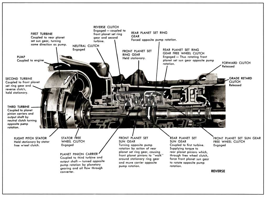
1958 Buick Operation of Components in Reverse Range
Description of torque converter operation in Reverse range will begin with car stationary, transmission in Reverse range and engine running at idling speed. The converter pump is turning with the engine and turbine members are stationary.
As engine is accelerated, oil projected from the pump strikes the first turbine vanes causing a buildup of torque. Upon development of sufficient force, the first turbine begins to move, turning its shaft and rear planet set sun gear.
This action causes rear planet set pinions to revolve the rear planet set ring gear opposite pump rotation. The rear planet set ring gear free wheel clutch thus engaged rotates the front planet set sun gear “free wheel” clutch, and forward clutch hub, with it opposite pump rotation. The front planet set sun gear turning opposite pump rotation
causes the front planet pinions to turn and “walk” around the stationary ring gear, turning the planet carrier and output shaft opposite pump rotation accomplishing reverse operation. The second turbine, held stationary, functions in a manner similar to a stator, aiding effective reverse operation.
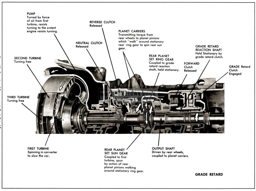
7-GRADE RETARDER
Construction
The grade retarder consists of:
A piston operated multiple disc clutch splined to a coaxial shaft operating outside transmission output shaft and coupled to the rear planet set ring gear.
Operation
As the transmission control is moved to Grade retard “G” position the forward clutch, neutral clutch and reverse clutch are disengaged and the grade retard clutch engaged, holding the grade retard reaction shaft and the rear planet set ring gear stationary. Forward motion of the car turns the output shaft and causes the rear planet pinions to “walk” around the stationary ring gear, spinning the rear planet set sun gear, first turbine shaft and first turbine in the same direction and faster than the converter pump. As the first turbine turns in the converter it tends to act as a pump, forcing converter oil forward through the second turbine, third turbine and back through the stator into the engine coupled converter pump which accelerates in speed and resists turning to the extent that the engine resists turning. Sufficient power is absorbed by the engine to allow safe descent of grades with the transmission in this range “G”.
1958 Buick Operation of Components in Grade Retard Range
8-FLIGHT PITCH DYNAFLOW HYDRAULIC CONTROL SYSTEM
The Flight Pitch Dynaflow transmission is supplied with sufficient oil to keep the torque converter filled when in operation and approximately four additional quarts for lubrication and operation of controls. Two oil pumps are used to provide oil circulation and pressure.
The hydraulic control system consists of the following main components:
- Front oil pump
- Rear oil pump
- Front and rear pump check valves
- Pressure regulator valve
- Manual control valve
- Stator control valve
- Stator modulator valve
- Stator piston control valve
- Limit valve
- Reverse Boost Valve
- Lubrication oil pressure pop-off valve
Oil Pumps
Two internal gear type oil pumps are used to provide oil circulation and pressure, to engage the clutches, control the stator valve and fill the converter and supply the necessary cooling and lubrication oil. The front oil pump, driven by lugs on the converter pump hub, is in operation whenever the engine is running. The rear oil pump is smaller than the front and is driven by the transmission output shaft; therefore it is in operation only when the rear wheels are turning.
The front oil pump is sufficient for all normal operation with engine running. When pushing the car to start engine, oil pressure is required to engage grade retard clutch. Under these conditions the front pump is not operating, but the rear pump, driven by the rear wheels, provides the necessary oil pressure and circulation.
The oil pumps are inter-connected by oil channels provided with check valves so they can operate together or independently. The pressure regulator valve and check valves are arranged in such a manner that a minimum of power is used in driving the pumps.
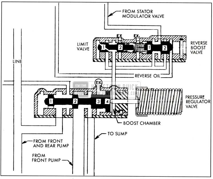
Pressure Regulator Valve
The pressure regulator valve operates in the valve body to regulate “line” pressure to a predetermined value under any operating condition, raising oil pressure during periods of heavy load or acceleration and lowering oil pressure in the system to a safe minimum during “cruise” operation.
Oil from the front and /or the rear pump enters the area between the first and second and second and third lands of the valve and flows through a hole in the first land to fill the cavity between the end of the valve body and the first land of the pressure regulator valve. Upon sufficient build-up of pressure against the end of the valve, the valve is moved against the pressure of the pressure regulator valve spring, opening an exit port between the first and second land of the pressure regulator valve which directs oil through the converter and oil cooler, accomplishing line pressure regulation at low car speeds.
At higher car speeds, the oil pump output is great enough to move the regulator valve further against its spring, opening a second exit port which directs oil to the front pump intake and sump. This causes a drop in front pump pressure which allows the front pump check valve spring to close the valve and rear oil pump pressure to hold the front pump check valve closed. The rear pump then supplies oil under pressure to the hydraulic system. The front pump under these circumstances absorbs very little power as it is not operating under pressure. See Figure 13.
1958 Buick Pressure Regulator Valve and Limit Valve
Manual Control Valve
The manual control valve has five lands that serve to open and close the proper ports to determine the operating range of the transmission and is connected by linkage to the transmission selector lever on the steering column. It can be set in five positions: Park, Reverse, Neutral, Drive, and Grade Retard.
Stator Control Valve and Stator Modulator Valve
The stator control valve and modulator valve govern the supply of oil at varying pressures to raise “line” pressure for more positive engagement of clutches during acceleration and to position the stator piston control valve. The stator control valve is connected to the carburetor linkage, and its position is determined by throttle opening.
As the throttle is opened, linkage moves the stator control lever to depress the stator valve which moves the stator modulator valve by means of a spring between the two valves. Movement of the modulator valve toward the end of the valve body opens a port between the modulator valve lands to oil at “line” pressure, which flows through a hole in the second land of the valve into a cavity between the second land and the end of the valve body. Build up of pressure in this cavity moves the modulator valve against spring pressure to partially shut off oil entry. This action accomplishes modulation or governing of “line” oil pressure.
Oil at modulated pressure flows between the lands of the modulator valve through an exit port and enters the stator control valve between the first and second lands. Upon sufficient throttle opening, an exit port is uncovered which directs oil through the reverse boost valve and limit valve to a boost chamber of the pressure regulator valve, which has the effect of increasing the pressure regulator valve spring pressure. Increased regulator valve spring pressure requires a higher oil pressure to move the regulator valve and consequently “line” pressure is raised.
Stator Piston Control Valve
Position of the Flight Pitch stator blades is determined by the position of the stator piston control valve as described in the Flight Pitch stator section.
Limit Valve and Reverse Boost Valve
Pressure of oil entering the boost chamber of the pressure regulator valve is governed by the limit valve and reverse boost valve. As described above, oil at modulated pressure enters the reverse boost valve between its lands and exits to the limit valve without affecting the reverse boost valve.
At the first stage of operation of the limit valve, modulated oil pressure is not great enough to build up pressure sufficient to move the limit valve against its spring. As a result, oil at a low modulated pressure is directed to the boost chamber of the pressure regulator valve. This stage of limit valve operation is not illustrated.
The second stage of operation occurs when modulated oil pressure is sufficient to move the limit valve against its spring to regulate (limit) the pressure of oil entering the boost chamber of the pressure regulator valve to approximately 12 p.s.i.
The third stage of limit valve operation occurs in reverse range. With the shift control valve in reverse “R” range, oil from the shift control valve is channeled to the reverse clutch and to the cavity between the second land of the reverse boost valve and the valve body. Oil under pressure in this area moves the boost valve against its spring and opens an exit port to direct oil to the space between the first and second lands of the limit valve. Oil flows through the hole in the first land of the limit valve and builds up pressure against the valve body and limit valve to move the valve. As spring pressure against the valve is increased by the change in position of the reverse boost valve, much higher oil pressure is required to move the limit valve. Under these circumstances, the limit valve directs oil at approximately 40 p.s.i. to the boost chamber of the pressure regulator valve, accomplishing an increase in line pressure for positive engagement of the reverse clutch. See Figure 13.
Lubrication Oil Pressure Pop-off Valve
Oil returning to the transmission from the oil cooler is used to lubricate the moving parts of the transmission. The pressure of the lubricating oil is maintained at approximately 30 p.s.i. by a spring loaded ball valve in the output shaft support.
Operation of Hydraulic Controls In Neutral “N” Range and Parking “P” Range
During operation in neutral the manual control valve is positioned as shown in Figure 14, “Oil Flow in Parking and Neutral.”
1958 Buick Oil Flow in Neutral and Park Range
The manual control valve is positioned further to the left during operation in parking. In both Parking and Neutral ranges, the neutral clutch piston oil supply is cut off and an exhaust port opened to disengage the neutral clutch. The forward and reverse clutches are also disengaged in a similar manner. Thus, the turbine members are allowed to turn but transmit no torque to the output shaft when operating in Parking or Neutral range.
The route of oil to the neutral clutch is illustrated and discussed in the Trouble Diagnosis Section.
Operation of Hydraulic Controls In Drive “D” Range 60 MPH-Cruise
During operation in Drive “D” range, the manual control valve is positioned as shown in Figure 15, “Oil Flow in Drive “D” Range 60 MPH Cruise.”
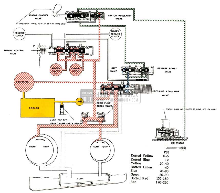
1958 Buick Oil Flow in Drive Range, 60 MPH Cruise
With the manual control valve thus positioned, oil is directed to the neutral clutch and forward clutch pistons solidly connecting the third turbine to the planet carriers and output shaft and preventing rotation of the rear free wheel clutch inner race. The neutral and forward clutches thus engaged, engine torque can be transmitted to the turbine members to drive and accelerate the car. The route of oil to the forward clutch is illustrated and discussed in the Trouble Diagnosis Section.
As the accelerator is depressed the stator modulator valve spring is compressed by the stator control valve (connected to carburetor linkage). Compression of the modulator valve spring provides higher modulated oil pressure exiting from the stator modulator valve chamber. This modulated oil is directed to the Flight Pitch stator piston control valve and to the space between the first and second lands of the stator control valve, which at half throttle is depressed sufficiently to open an exit port directing oil through the reverse boost valve to the space between the first and second lands of the limit valve. A hole in the first limit valve land allows the limit valve to position itself as described previously and direct oil at limited pressure (approx. 12 psi.) to the boost chamber of the pressure regulator valve. This “boost” raises line pressure to 170-190 psi. thus insuring positive engagement of the neutral and forward clutches and insuring ample oil flow through the converter and oil cooler for proper cooling and lubrication of the transmission.
Operation of Hydraulic Controls In Drive “D” Range-Wide Open Throttle
Hydraulic component operation in Drive “D” range at wide open throttle is similar to cruise with the following exceptions: (See Figure 16.)
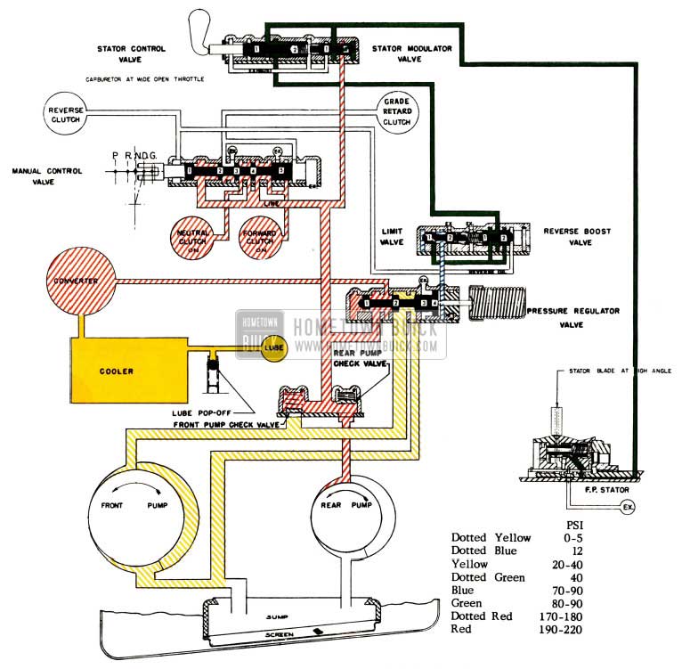
1958 Buick Oil Flow in Drive Range, Wide Open Throttle
The stator control valve at wide open throttle is fully depressed further compressing the stator modulator valve springs. Greater pressure on the stator modulator valve springs provides modulated oil at higher pressure (80-90 psi.). The modulated oil flows to the limit valve which limits the pressure of oil entering the boost chamber of the pressure regulator valve to 12 psi. the same as during cruise operation at half throttle. However, higher modulated oil pressure at the stator piston control valve shifts the valve and allows converter charging pressure to move the stator piston and set the stator blades at high angle as described in the Flight Pitch Stator Section.
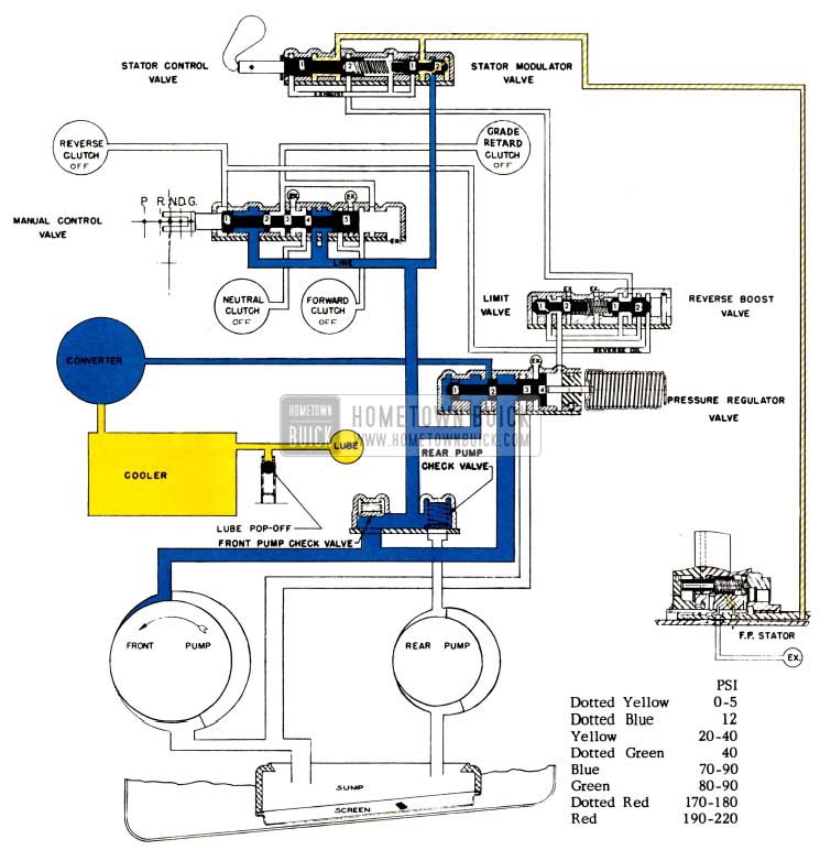
Operation of Hydraulic Controls In Reverse “R” Range
With the transmission selector lever set in Reverse “R” range the manual control valve is positioned as shown in Figure 17, “Oil Flow in Reverse “R” Range”.
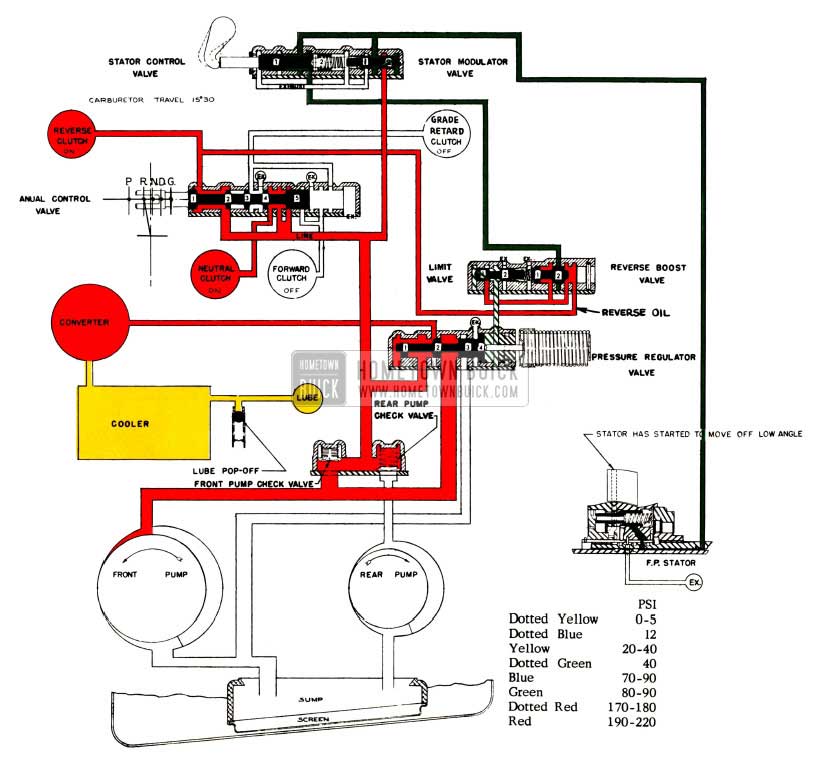
1958 Buick Oil Flow In Reverse Range
Oil supply to the grade retard and forward clutch pistons is thus cut off and exhaust ports opened to allow rapid disengagement of the clutches. Oil at line pressure is channeled to the neutral and reverse clutch pistons and also to the reverse boost valve.
Oil from the reverse clutch piston supply is directed to the space between the second land of the reverse boost valve and the valve retainer. Oil pressure in this space moves the boost valve against spring pressure toward the limit valve, closes the modulated oil entrance port and opens an exit port to the limit valve. The spring between the reverse boost valve and limit valve thus compressed, higher oil pressure is required to move the limit valve. Consequently line boost pressure to the pressure regulator valve boost chamber is raised to approximately 40 psi. raising line pressure to approximately 200 psi. Higher line pressures during operation in Reverse “R” range are necessary to insure positive engagement of the reverse clutch. As previously described, reverse operation of the Flight Pitch Dynaflow is accomplished by holding the second turbine-front planet set ring gear stationary. The second turbine then functions in a manner similar to a stator having sharply curved vanes operating in the oil stream from the converter pump. Thus to preclude the possibility of second turbine-front planet set ring gear rotation during operation in reverse range, a larger more positively engaged clutch is used than is necessary for Forward, Neutral or Grade Retard clutch applications.
Operation of Hydraulic Controls In Grade Retard “G” Range
With the shift control lever positioned in Grade Retard “G” range the manual control valve is positioned as shown in Figure 18 “Oil Flow in Grade Retard “G” Range.”
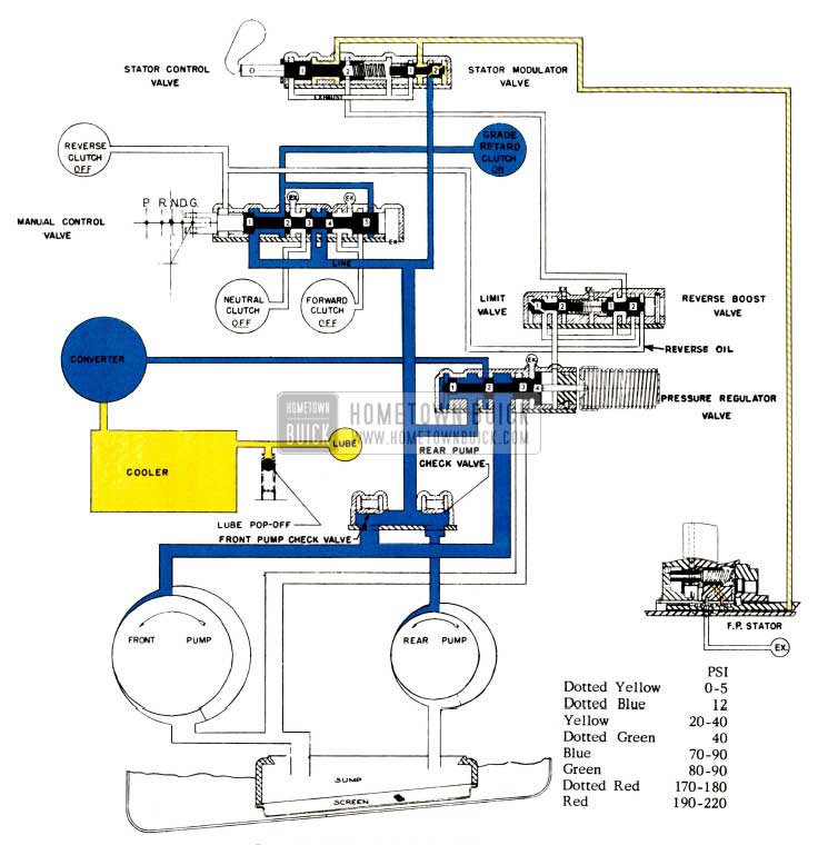
1958 Buick Oil Flow in Grade Retard Range
The valve thus positioned shuts off the oil supply to the forward clutch, neutral clutch and reverse clutch pistons and opens exhaust ports to provide rapid disengagement of the clutches. Oil at line pressure is directed to the grade retard clutch piston engaging the grade retard clutch to slow the car.
The route of oil to the grade retard clutch piston is illustrated and discussed in the trouble diagnosis section.
9-FLIGHT PITCH STATOR
DESCRIPTION
The 1958 Flight Pitch stator consists of:
- Twenty movable stator blades and cranks. See Figure 19.
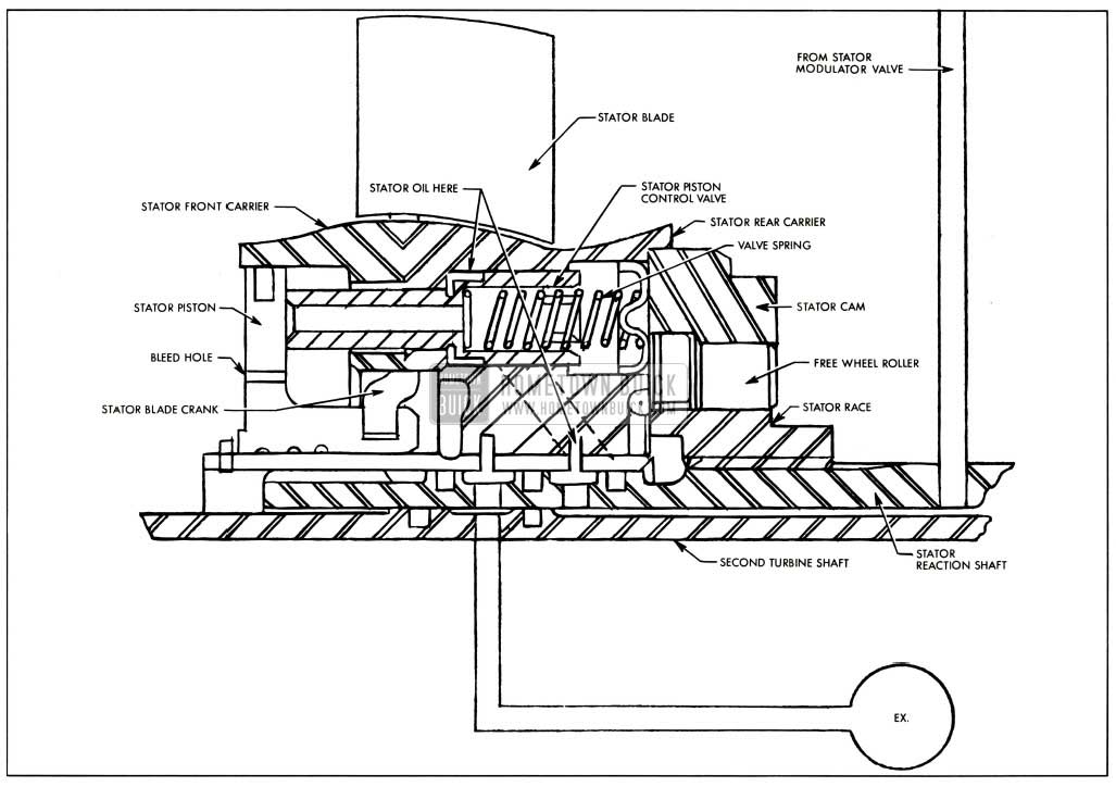
1958 Buick Flight Pitch Stator
- A Stator piston which acts on the cranks to set the blades at any angle from Low to High.
- A stator piston control valve, sensitive to throttle opening, which controls the position of the stator piston.
- A front and rear carrier which supports the blade cranks and houses the piston and valve mechanism.
- A free wheel clutch which allows the stator to free wheel when torque multiplication is not required.
OPERATION
- The stator blades of the Flight Pitch transmission can be set at any position between high and low.
- As the accelerator pedal is depressed beyond approximately half throttle position, carburetor linkage has moved the stator control lever which causes oil under pressure to be directed to a cavity formed by the shoulder of the stator piston control valve and the stator rear carrier. See Figure 19.
- This oil pressure is proportional to throttle opening; that is, the wider the throttle opening, the higher the oil pressure bearing on the shoulder of the piston control valve.
- When the throttle has been opened sufficiently to cause the oil pressure bearing on the shoulder of the control valve to reach 38-40 psi., the valve moves against its spring until the resistance of the spring balances the force of the oil pressure.
- The forward end of the stator control valve extends through a cavity behind the stator piston and bears against the rear face of the piston except when the valve is caused to move by an increase in throttle opening. The stator piston moves in a bore formed by the stator front carrier and a sleeve extending forward from the stator rear earner. The stator piston has a small “bleed hole” which allows oil to fill the cavity behind the piston to nearly equal the converter charging pressure at the front of the piston except when a change of stator blade position is desired. This “bleed hole” is actually the gap in the stator piston oil ring.
Operation During a Change to Higher Angle
Wider throttle opening causes oil at increased pressure to move stator control valve rearward against spring pressure.
- Front end of stator valve leaves rear face of stator piston.
- Oil flows from cavity behind stator piston through center of valve, causing decrease in oil pressure behind piston.
- Converter charging pressure moves piston rearward till it touches valve and oil flows through bleed hole to fill rear cavity.
- As piston moves rearward, it rotates stator blade cranks to set stator blades at higher angle.
Operation During Change to Lower Angle
- Decreased throttle opening lowers oil pressure at valve shoulder.
- Valve spring moves valve forward to touch piston.
- Flow of oil across stator blades forces them to lower angle.
- Valve follows piston forward till oil pressure on shoulder and spring pressure are equal.
Operation with No Change In Blade Angle (Blades Not at Low Angle)
- Oil pressure on shoulder of valve and spring pressure equal-valve does not move in bore.
- Flow of oil across stator blades tends to move them to lower angle.
- Force of oil across stator blades tends to rotate cranks and move piston forward.
- As piston tends to move forward, oil pressure is lost from cavity at rear of piston and piston is immediately moved rearward by converter charging pressure to touch valve and allow oil to “bleed” into cavity. This stator blade angle remains constant till throttle opening is changed.
Leave A Comment
You must be logged in to post a comment.