1958 BUICK FLIGHT PITCH DYNAFLOW DISASSEMBLY, INSPECTION AND REASSEMBLY
BUSHING REPLACEMENT
Special service tools are available which will allow the replacement of most of the bushings used in the Flight Pitch Dynaflow if they are found to be worn or scored. The bushings which cannot be replaced (due to their being machined following assembly) are as follows:
- Front Pump Bushing
- Front Planet Carrier Bushing
- Output Shaft Support Bushing
The procedure for removal of the worn or scored bushing and installation of the replacement bushing follows in sequence the disassembly of the affected part. Care should be exercised when installing a new bushing to be certain that bushing is started squarely into lx>re. The bushing should also be driven fully into bore until tool bottoms.
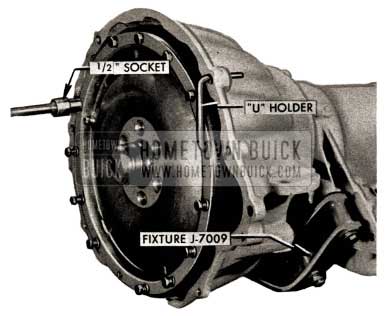
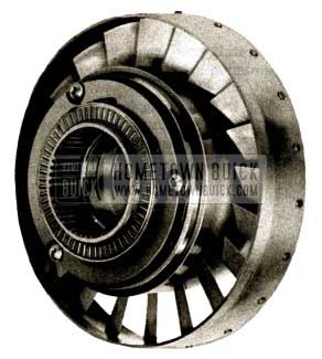
- Assemble Flight Pitch Dynaflow to Fixture, J-7009. Remove twelve converter cover bolts using “U” holder and 1/2″ socket. Mark with paint or chalk position of cover to converter pump. The converter pump and cover are balanced as an assembly and to preserve this balance, these two parts should always be reassembled in the same position.
1958 Buick Flight Pitch Dynaflow Assembly
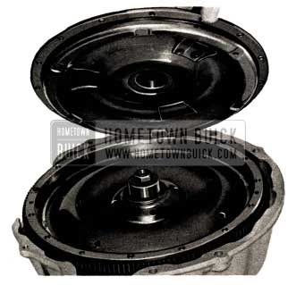
- Pry to loosen, remove cover and, “O” ring. Discard “O” ring.
1958 Buick Flight Pitch Dynaflow Remove O-Ring
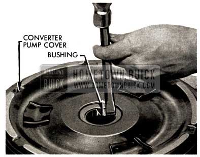
2A. Examine converter pump cover bushing. If worn or scored, collapse bushing with chisel and remove.
1958 Buick Flight Pitch Dynaflow Converter Pump
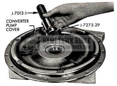
2B. Install new converter pump cover bushing using J-7013-1 Handle and J-7273-29 Installer.
1958 Buick Flight Pitch Dynaflow Install Converter Pump
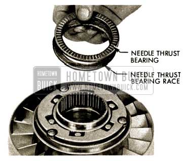
- Remove select fit bearing races and needle thrust bearing. (Between first turbine hub and converter pump cover). Place in converter pump cover.
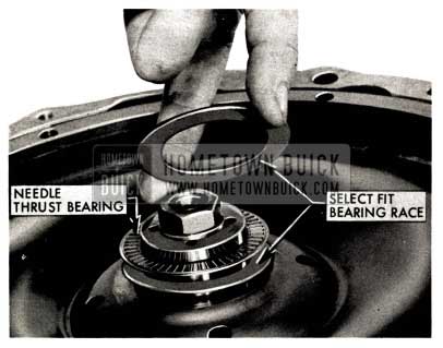
1958 Buick Flight Pitch Dynaflow Select Fit Bearing Races
- Loosen first turbine shaft nut using “U” holder and 15/16″ socket.
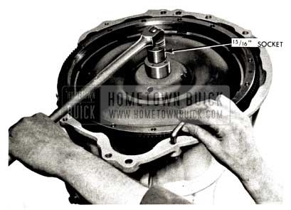
1958 Buick Flight Pitch Dynaflow First Turbine Shaft
- Remove nut and special washer. Discard washer.
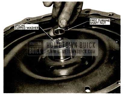
1958 Buick Flight Pitch Dynaflow Install Special Washer
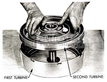
- Use two screwdrivers or other suitable tool to lift the complete 1st, 2nd and 3rd turbine assembly, remove from transmission case.
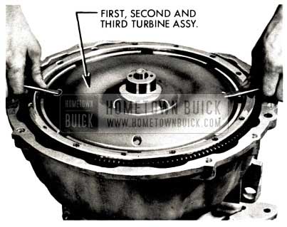
1958 Buick Flight Pitch Dynaflow First and Second Turbine Assembly
Set assembly on bench shafts up.
TURBINE DISASSEMBLY, INSPECTION AND REASSEMBLY
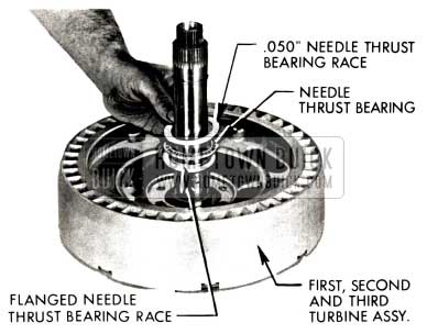
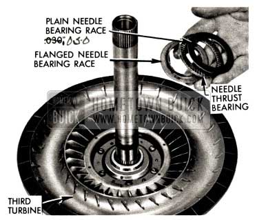
- Remove needle bearing flanged needle bearing race and .050″ plain bearing race from second turbine hub. NOTE: These races and bearing may have remained on top of stator.
1958 Buick Flight Pitch Dynaflow Inspect Flanged Needle Bearing Race
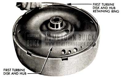
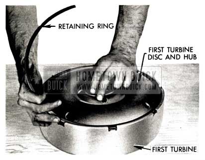
- Set assembly shafts down through hole in bench. Remove first turbine to disc and hub retainer ring. Use a thin bladed screwdriver at inner edge of ring to raise edge of ring. Press on outer edge of ring to slide ring up slope of thin screwdriver over step of first turbine disk and hub.
1958 Buick Flight Pitch Dynaflow Assembly Shafts
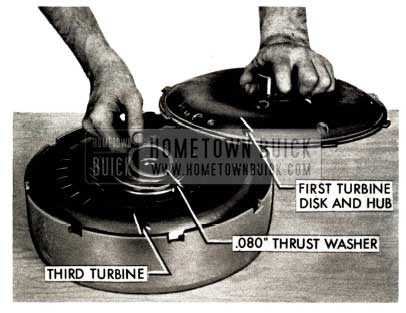
- Remove 1st turbine disc, hub and .080″ bronze thrust washer on 3rd turbine hub.
1958 Buick Flight Pitch Dynaflow Bronze Thrust Washer
- Remove 3rd turbine, flanged needle bearing race, needle bearing and .030″ plain needle bearing race.
1958 Buick Flight Pitch Dynaflow Remove Third Turbine
10A. Examine third turbine front bushing. If worn or scored, cut out bushing with chisel.
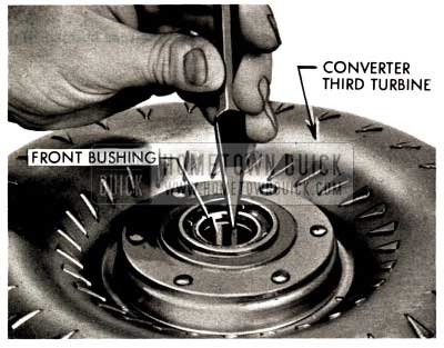
1958 Buick Flight Pitch Dynaflow Third Turbine Front Bushing
10B. Install new third turbine front bushing using J-7013-1 and J-7273-25.
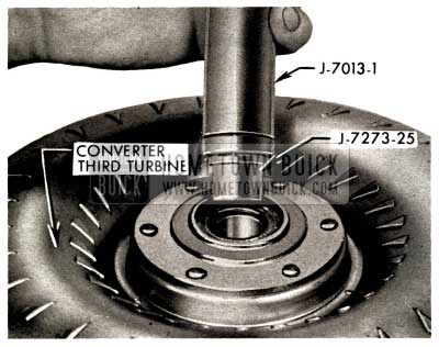
1958 Buick Flight Pitch Dynaflow Install Third Turbine Front Bushing
10C. Examine third turbine rear bushing. If worn or scored, cut out bushing with chisel.
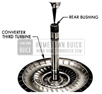
1958 Buick Flight Pitch Dynaflow Third Turbine Rear Bushing
CONVERTER THIRD TURBINE
10D. Install new third turbine rear bushing using J-7013-1 and J-7273-25.
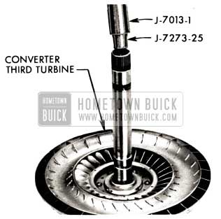
1958 Buick Flight Pitch Dynaflow Install Third Turbine Rear Bushing
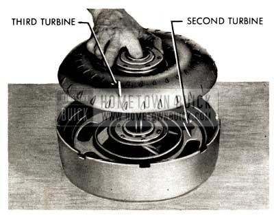
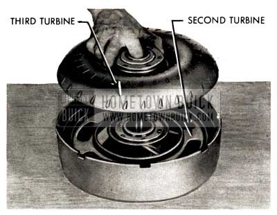
- Remove 2nd turbine.
1958 Buick Flight Pitch Dynaflow Remove Second Turbine
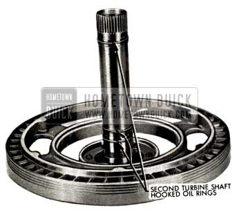
- Inspect and if necessary to replace, unhook, expand and remove three second-turbine shaft hooked oil rings.
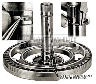
1958 Buick Flight Pitch Dynaflow Remove Second Turbine Shaft
12A. Examine second turbine front bushing. If worn or scored, collapse bushing with chisel and remove.
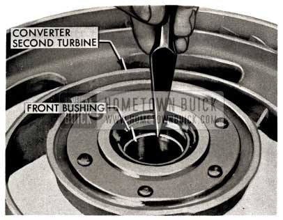
1958 Buick Flight Pitch Dynaflow Examine Second Turbine Front Bushing
12B. Install new second turbine front bushing using J-7013-1 Handle and J-7272-26-6 (Counter bore on 6 toward handle).
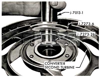
1958 Buick Flight Pitch Dynaflow Install Second Turbine Front Bushing
12C. Examine second turbine rear bushing. If worn or scored, collapse bushing with chisel and remove.
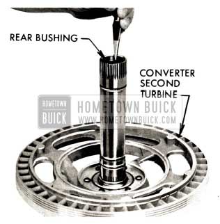
1958 Buick Flight Pitch Dynaflow Examine Second Turbine Rear Bushing
12D. Install new second turbine rear bushing using J-7013-1 Handle and J-7273-26 Installer.
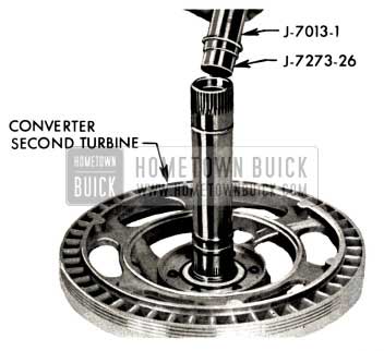
1958 Buick Flight Pitch Dynaflow Install Second Turbine Rear Bushing
- Expand and install new hooked oil rings on 2nd turbine shaft. Hook ends of rings by holding one end firmly in groove and working other end around to hook.
NOTE: Second turbine shaft oil rings are slightly smaller (.050″) than two rings used on the output shaft. These rings must not be interchanged with those used on the output shaft.
1958 Buick Flight Pitch Dynaflow Install Hooked Oil Rings
REASSEMBLY OF TURBINES
- With 1st turbine on bench, insert 2nd turbine with oil rings in place through hole in bench to rest on 1st turbine.
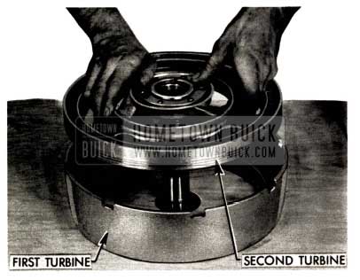
1958 Buick Flight Pitch Dynaflow Reassembly of Turbines
- Inspect and if necessary, install new flanged needle bearing race, flange “up”, needle thrust bearing (1 3/4″ X 2 1/2″), and plain needle bearing race (.030″) on 3rd turbine hub. Hold in place with heavy lube.
NOTE: Always measure needle bearings and races. Some are within .010″ thickness and 1/16″ diameter of each other and can easily be incorrectly assembled.
1958 Buick Flight Pitch Dynaflow Install Flanged Needle Bearing Race
- With needle bearing and races held in place with heavy lube, insert 3rd turbine shaft into 2nd turbine shaft. Lower into position.
NOTE: Heavy lube referred to in this manual can be wheel bearing grease or chassis lube. Use only enough to hold bearings and races in place.
1958 Buick Flight Pitch Dynaflow Flight Install First Turbine Disc
- Inspect and, if necessary, place new .080″ bronze thrust washer on hub of 3rd turbine, and position 1st turbine disc and hub with tangs in slots of 1st turbine
1958 Buick Flight Pitch Dynaflow Bronze Thrust Washer
- Install 1st turbine disc and hub retaining ring so high edge will engage the groove in the 1st turbine and the inner lower edge forces down on the 1st turbine disc and hub. Tap solidly into groove and inspect for proper installation.
1958 Buick Flight Pitch Dynaflow Install First Turbine Disc
- With assembly on bench, shafts up, inspect and, if necessary, install new flanged needle bearing race, flange “up” on second turbine hub, next, needle thrust bearing (1 3/4 ” X 2 1/2″) and last, .050″ bearing race which is thicker than the other plain races used in the turbine build up. Set completed sub-assembly aside if further work is to be done on the transmission.
1958 Buick Flight Pitch Dynaflow Inspect Flanged Needle Bearing Race
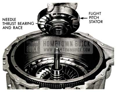
- Lift converter pump until stator race is clear of splines on reaction shaft (approximately 2 1/2″). Lower converter pump and remove the stator. To avoid pinching fingers, use cuation when lowering pump.
1958 Buick Flight Pitch Dynaflow Remove Needle Thrust Bearing
Remove needle thrust bearing and bearing race (Stator cam to converter pump hub).
FLIGHT PITCH STATOR OVERHAUL
- Pull out stator free wheel race by rotating clockwise.
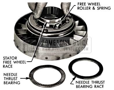
1958 Buick Flight Pitch Dynaflow Flight Pitch Stator Overhaul
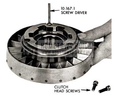
- Remove 3 special clutch head screws from stator cam to stator carrier using Tool 10-167-1.
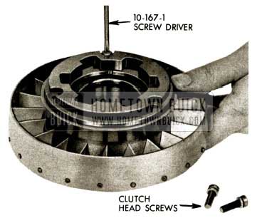
1958 Buick Flight Pitch Dynaflow Assemble Stator Free Wheel Cam
- Pry up stator free wheel cam and bronze washer with screwdriver, using care to avoid damage to washer. Remove cam and washer.
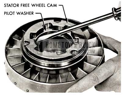
1958 Buick Flight Pitch Dynaflow Stator Free Wheel Cam
STATOR REAR CARRIER ASSY.
- Remove five clutch head front to rear carrier screws using Tool 10-167-3.
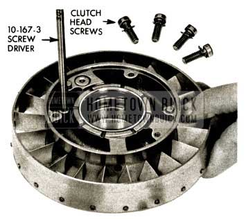
1958 Buick Flight Pitch Dynaflow Install Clutch Head Screws
- Invert assembly, expand and remove stator piston retaining ring from rear carrier to stator piston.
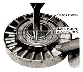
1958 Buick Flight Pitch Dynaflow Remove Stator Piston Retaining Ring
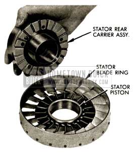
- Invert assembly and rotate all stator blades to extreme high angle position and remove stator rear carrier assembly from front carrier. Remove blades and stator blade ring from stator front carrier and piston assembly.
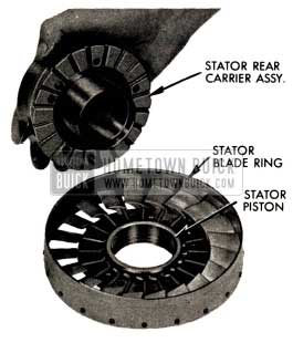
1958 Buick Flight Pitch Dynaflow Stator Blade Ring
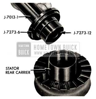
26A. Examine stator rear carrier bushing. lf worn or scored, remove bushing using tool J-7013-1 Handle and J-7273-12 Remover.
1958 Buick Flight Pitch Dynaflow Install Sun Gear Bushing
26B. Install new stator rear carrier bushing using tool J -7013-1 Handle and J -7273-6-12 Installer. (Counterbore on 6 toward handle).
1958 Buick Flight Pitch Dynaflow Install Stator Rear Carrier Bushing Ring
- Remove stator piston and ring from front carrier.
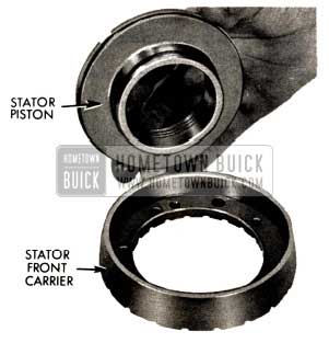
1958 Buick Flight Pitch Dynaflow Remove Stator Piston
- Expand and remove ring from stator piston with snap ring pliers.
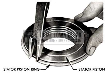
1958 Buick Flight Pitch Dynaflow Remove Ring
- Suitably support stator rear carrier and remove stator piston control valve, spring and retainer from stator rear carrier by rapping sharply on valve with a plastic hammer.
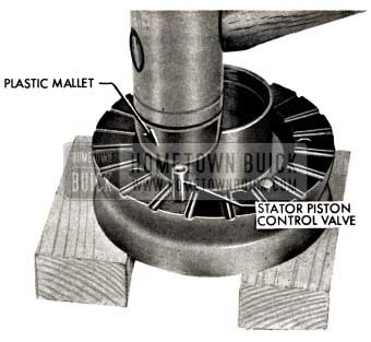
1958 Buick Flight Pitch Dynaflow Stator Piston Control Valve
- For gaging purposes only: assemble stator piston shoulder “up” to rear carrier and press together. Insert valve in bore of rear carrier.
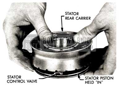
1958 Buick Flight Pitch Dynaflow Stator Control Valve
- Insert gage J-7116 in stator control valve. With piston held against carrier and tool in place, top of tool should be flush with boss of stator rear carrier.
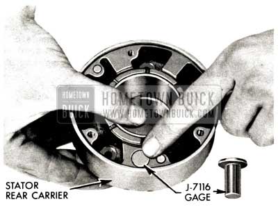
1958 Buick Flight Pitch Dynaflow Gage J-7116
- If gage is below surface of stator rear carrier, add shims to bring gage as close to flush. with surface as possible. Shims are available in two sizes only, .007” and .021″. Total thickness of shims used should not exceed .042″. If thickness of shims required exceeds .042” stator rear carrier, stator piston or stator valve may require replacement.
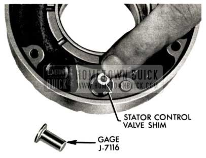
1958 Buick Flight Pitch Dynaflow Stator Control Valve Shim
- After stator valve has been checked and shims added if necessary, assemble valve, spring, and retainer to stator rear carrier. NOTE: Be certain shims lay flat in position inside valve bore.
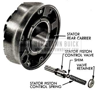
1958 Buick Flight Pitch Dynaflow Stator Rear Carrier
- Tap valve retainer into stator carrier squarely and flush with stator carrier surface to .010″ below. Use flat tool to drive retainer to prevent cocking of retainer during installation.
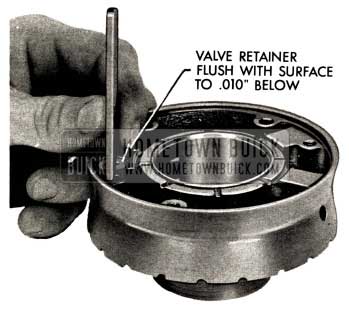
1958 Buick Flight Pitch Dynaflow Valve Retainer Flush
- Insert stator piston ring in bore of stator front carrier. (Check gap with feeler gage – should be .090″ +/- .010″.) NOTE: This gap serves as the piston “bleed” hole for the stator piston.
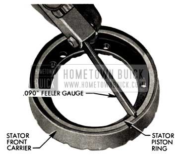
1958 Buick Flight Pitch Dynaflow Stator Piston Ring
- Expand and install stator piston ring on stator piston.
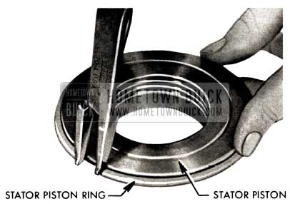
1958 Buick Flight Pitch Dynaflow Install Stator Piston Ring
- Install piston and ring into stator front carrier by tilting and inserting gap side of ring first and then pressing in.
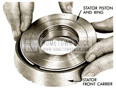
1958 Buick Flight Pitch Dynaflow Install Piston
- Set stator front carrier assembly and piston on stator free wheel cam and pilot washer assembly to hold piston “in.” Support edge of stator blade ring and insert blades into carrier and piston assembly. Be sure edge of ring nearest holes is “down” as pictured.
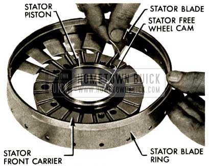
1958 Buick Flight Pitch Dynaflow Stator Front Carrier Assembly
- Install last blade by crowding several adjacent blade cranks together.
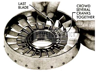
1958 Buick Flight Pitch Dynaflow Install Blades
- With stator blades at extreme high angle position, assemble rear stator carrier assembly to stator front carrier assembly. Note position of dowels and dowel holes.
1958 Buick Flight Pitch Dynaflow Stator Blades
- Install five clutch head screws and lock washers using Tool 10-167-3. Torque to 10- 12 ft. lbs.
1958 Buick Flight Pitch Dynaflow Install Clutch Head Screws
- Install stator piston retaining ring on stator rear carrier sleeve. NOTE: Tangs on retaining ring must enter slots in sleeve. Move stator blades from high to low angle several times. Check for free operation.
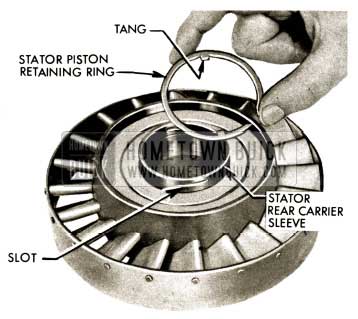
1958 Buick Flight Pitch Dynaflow Install Stator Piston Retaining Ring
- Inspect and if necessary, suitably support stator free wheel cam and remove pilot washer using a plastic hammer and drift.
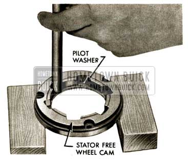
1958 Buick Flight Pitch Dynaflow Inspect Stator Free Wheel Cam
- Install new pilot washer in stator free wheel cam using a plastic hammer. Make sure pilot washer is seated in bore of cam.
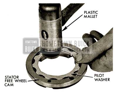
1958 Buick Flight Pitch Dynaflow Install Pilot Washer
- Assemble stator free wheel cam and pilot washer assembly to stator rear carrier with three clutch head screws and lock washers using Tool 10-167-1. Note position of dowels and dowel holes. Torque screws to 10 – 12 ft. lbs.
1958 Buick Flight Pitch Dynaflow Remove Special Clutch Head Screws
- Insert stator free wheel clutch inner race, small diameter end up, into pilot washer. Inner race should rotate freely in pilot washer.
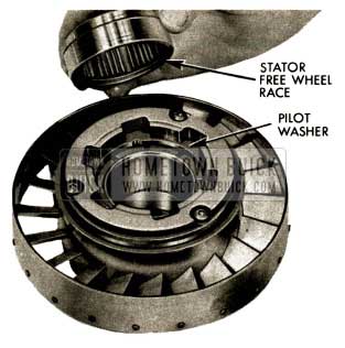
1958 Buick Flight Pitch Dynaflow Insert Stator Free Wheel Clutch
- Install free wheel clutch rollers and springs-roller toward narrow end of cam opening, and spring at wide end of opening. Inner race should rotate freely in clockwise direction and lock on counter-clockwise rotation.
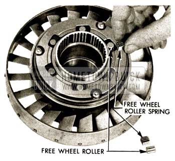
1958 Buick Flight Pitch Dynaflow Install Free Wheel Clutch Rollers
- Apply heavy lube and install bearing race and needle thrust bearing (2 1/4″ I.D. X 3″ O.D.) on stator free wheel race. NOTE: Race next to free wheel rollers and springs.
NOTE: If the needle thrust bearing or race is scored or worn, both should be replaced.
1958 Buick Flight Pitch Dynaflow Install Bearing Race
- Set assembly aside if further work is to be done on transmission.
1958 Buick Flight Pitch Dynaflow Fan Assembly
- Remove converter pump.
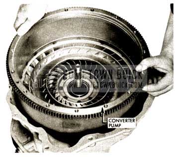
1958 Buick Flight Pitch Dynaflow Remove Converter Pump
- With transmission horizontal remove front pump seal with front pump in transmission using slide hammer and J-7005. Thread tool into seal until threads are engaged with sheet metal portion of seal.
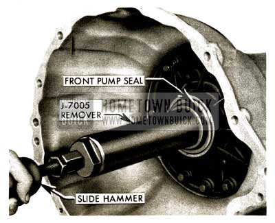
1958 Buick Flight Pitch Dynaflow Remove Front Pump Seal
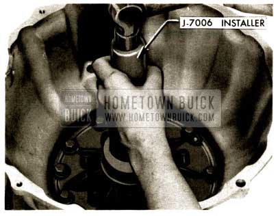
- Install new front pump seal with pump in transmission using Tool J- 7006.
NOTE: It is not necessary to remove the planet sets, first turbine shaft, and output shaft assembly to remove and reinstall the front pump seal or the complete front pump-reverse piston assembly.
1958 Buick Flight Pitch Dynaflow Install Front Pump Seal
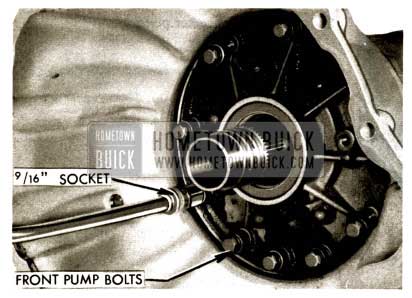
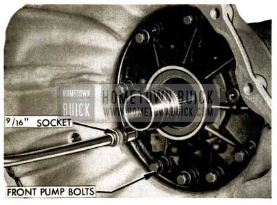
- Remove ten front pump to case bolts (9/16” socket.)
1958 Buick Flight Pitch Dynaflow Remove Front Pump to Case Bolts
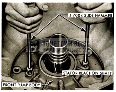
- With transmission front end up install two J-7004 slide hammers in tapped holes of front pump body and hammer evenly to remove front pump, stator reaction shaft and flange, and reverse clutch piston assembly. Set assembly on bench and remove slide hammers.
1958 Buick Flight Pitch Dynaflow Install J-7004 Slide Hammers
DISASSEMBLY, INSPECTION & REASSEMBLY OF FRONT PUMP, STATOR REACTION SHAFT AND FLANGE, & REVERSE CLUTCH PISTON
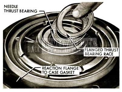
- Remove needle thrust bearing and flanged rear thrust bearing race {between stator reaction shaft and front planet ring gear assembly). Remove reaction flange to case gasket .
NOTE: This bearing and rear race may have stuck to front planet set ring gear carrier during disassembly.
1958 Buick Flight Pitch Dynaflow Needle Thrust Bearing
- Remove reverse clutch piston. Use pliers to grip ribs of piston if piston sticks in bore.
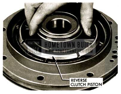
1958 Buick Flight Pitch Dynaflow Remove Reverse Clutch Piston
- Remove reverse piston seal.
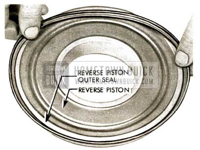
1958 Buick Flight Pitch Dynaflow Remove Reverse Piston Seal
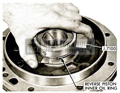
- Inspect and if necessary to replace, unhook reverse piston oil ring, using Tool 1-7100. Assemble tool on ring so ring is forced solidly in groove and movable arm contacts ring approximately 1/4” from end . Press in on movable arm and pry up free end of ring with small screwdriver. Release arm.
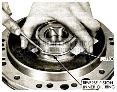
1958 Buick Flight Pitch Dynaflow Reverse Piston Oil Ring
- Expand reverse piston oil ring and remove from reaction shaft flange hub.
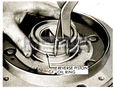
1958 Buick Flight Pitch Dynaflow Expand Reverse Piston Oil Ring
- Expand and install new reverse piston oil sealing ring on reaction shaft. Hook ends using Tool J-7100. Assemble tool on ring so ring is forced solidly in groove and movable arm contacts ring approximately 1/4″ from end. Press in on arm to hook ends.
1958 Buick Flight Pitch Dynaflow Install Reverse Piston Oil Sealing Ring
- Remove front pump body to case sealing ring (square section).
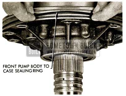
1958 Buick Flight Pitch Dynaflow Remove Front Pump Body
- Inspect flanged needle thrust bearing race (between stator reaction shaft and front planet ring gear assembly).
NOTE: This bearing race is specially hardened and is very brittle. It is not likely it will need replacement; however, if it is to be replaced, be careful to use eye protection as the race may shatter when struck with chisel.
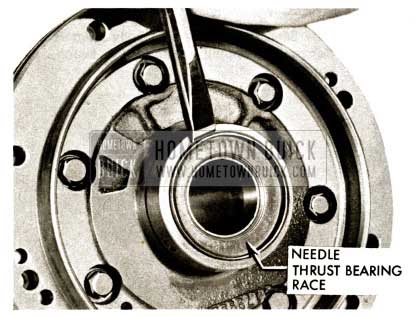
1958 Buick Flight Pitch Dynaflow Inspect Flanged Needle Thrust Bearing Race
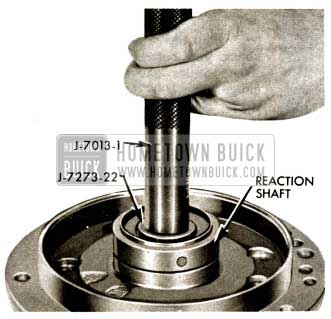
- Inspect reaction shaft end; clean up all burrs and nicks.
Install new flanged needle thrust bearing race in reaction shaft using Tool J-7013-1 Handle, and J-7013-21 Installer.
1958 Buick Flight Pitch Dynaflow Install Second Turbine Shaft
- Remove seven reaction flange to front pump body bolts (1/2″ socket).
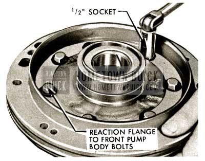
1958 Buick Flight Pitch Dynaflow Reaction Flage
- Separate front pump body from reaction flange by tapping assembly on bench, shaft down.
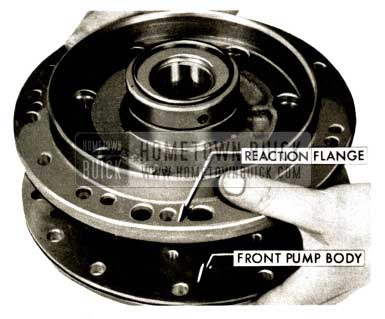
1958 Buick Flight Pitch Dynaflow Front Pump Body
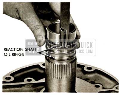
- Inspect and if necessary to replace, unhook and expand the three reaction shaft oil rings. Remove from reaction shaft.
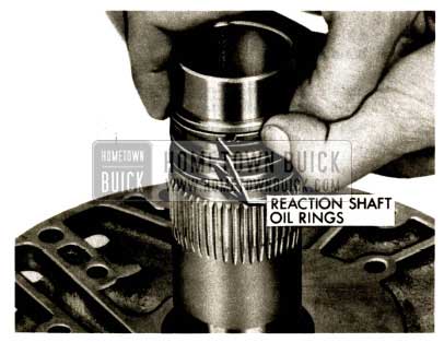
1958 Buick Flight Pitch Dynaflow Reaction Shaft Oil Rings
66A. Examine second turbine shaft to reaction shaft bushing. If worn or scored, collapse bushing with cape chisel. Remove bushing.
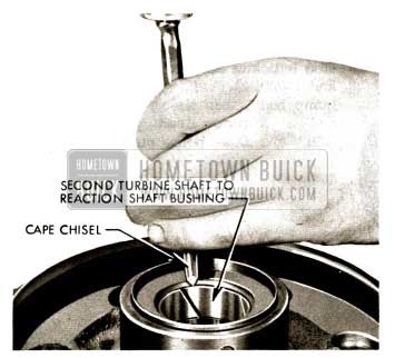
1958 Buick Flight Pitch Dynaflow Second Turbine Shaft
66B. Install new second turbine shaft to reaction shaft bushing using Tool J-7013-1 Handle and J-7273-22 Installer.
1958 Buick Flight Pitch Dynaflow Install Second Turbine Shaft
- Using snap ring pliers, carefully expand and install three new reaction shaft oil rings in grooves.
Hold one end of hooked ring firmly in groove and work other end of ring into position. Rotate hooked ring in groove to check for burrs or dirt that may be present.
1958 Buick Flight Pitch Dynaflow Install Reaction Shaft Oil Rings in Grooves
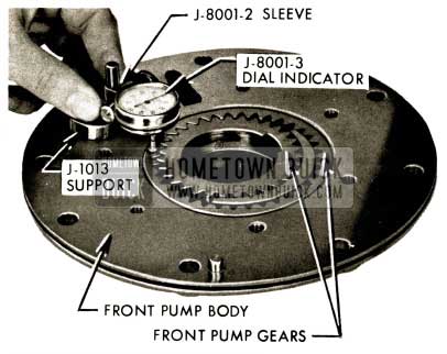
- Check front pump gear end clearance using Dial Indicator Support J-1013, J-8001-2 Sleeve, and J -8001-3 Dial Indicator. Zero indicator on pump body, then slide plunger to rest on gears, one at a time. Reading should be between .001” and .002″ below pump body.
1958 Buick Flight Pitch Dynaflow Check Front Pump Gear End
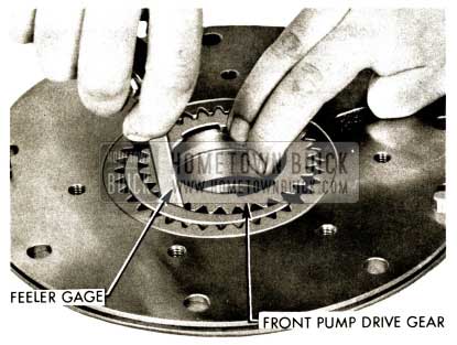
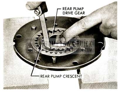
- Hold drive gear away from crescent and check gap between gear and crescent with a .009″ feeler gauge and then a .017″feeler gauge. The .009″ gauge should “go” and the .017″ should “not go”. If the .009″ does “not go” the clearance is less than .010″ required. If the .017″ “goes” the clearance is more than the .016″ maximum allowed . Replace pump if necessary.
1958 Buick Flight Pitch Dynaflow Front Pump Drive Gear
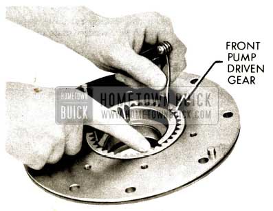
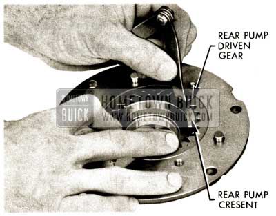
- Hold front pump driven gear away from crescent and check gap between gear and crescent with a .004″ feeler gauge and then a .010″ feeler gauge. The .004″ gauge should “go” and the .010″ should “not go”. If the .004″ does “not go”, the clearance is less than .005″ required. If the 010″ “goes” the clearance is more than the .009” maximum allowed.
1958 Buick Flight Pitch Dynaflow Front Pump Driven Gear
- Remove front pump gears by lifting straight up.
NOTE: All surfaces of these gears are accurately ground and must be protected against nicks, scratches and dirt of any kind.
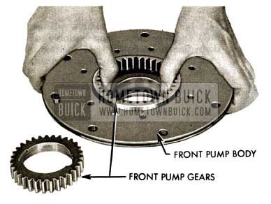
1958 Buick Flight Pitch Dynaflow Remove Front Pump Gears
- If front pump seal is to be replaced at this time rather than with pump in transmission, suitably support pump body and drive out front pump seal using drift and hammer.
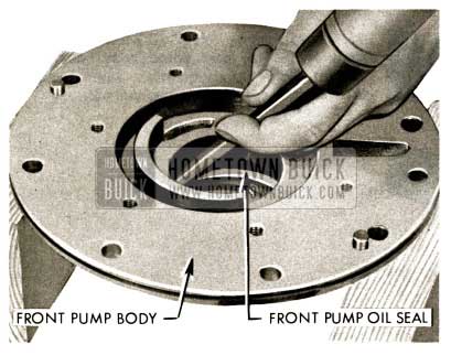
1958 Buick Flight Pitch Dynaflow Front Pump Oil Seal
- Clean and lubricate front pump gears and install in pump body by lowering straight down into body. Do not use force.
NOTE : Front pump drive gear must be installed with notched driving flange “up” and. counter-bored side toward front pump seal.
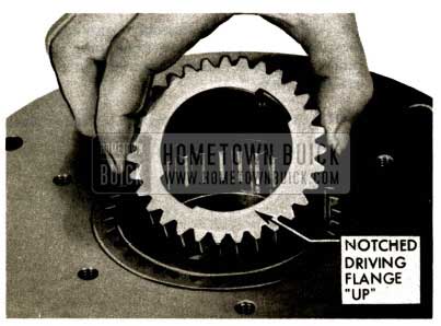
1958 Buick Flight Pitch Dynaflow Lubricate Front Pump Gears
- Lubricate with Dynaflow oil and carefully assemble front pump assembly to reaction shaft flange assembly. Note position of dowel pins in pump body and holes in reaction shaft flange.
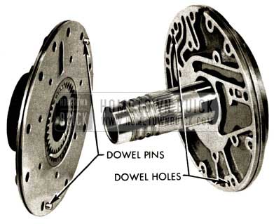
1958 Buick Flight Pitch Dynaflow Lubrication
- Install seven 5/16″-18 X 1 7/8″ reaction shaft flange to front pump body bolts (1/2″ socket). Tighten alternately and evenly to 20 – 25 ft. lbs. using a torque wrench.
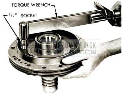
1958 Buick Flight Pitch Dynaflow Reaction Shaft Flange
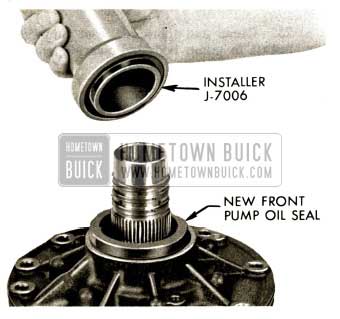
- Suitably support assembly to protect needle bearing race and drive new front pump seal into front pump body using hammer and Seal Installer J – 7006.
NOTE: Reaction shaft pilots tool to insure square seating of seal.
1958 Buick Flight Pitch Dynaflow Install Front Pump Oil Seal
- Install new reverse piston seal with lip away from ribbed side of piston.
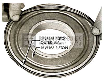
1958 Buick Flight Pitch Dynaflow Install Reverse Piston Seal
- Lubricate reverse piston seal and install piston assembly in bore of reaction flange by running a smooth edged feeler gauge around reverse piston to keep lip of seal down. Use care to prevent damage to seal.
1958 Buick Flight Pitch Dynaflow Lubricate Reverse Piston Seal
- Install new front pump body to case sealing ring squarely in groove of front pump body.
If further work is to be done on transmission assembly, set pump aside, otherwise reinstall pump in case using a new gasket and 3/8″ – 16 guide pins J-7003. Refer to step #259.
IMPORTANT: Be certain the 1 3/4″ X 2 1/2″ needle thrust bearing is correctly positioned in the cupped bearing race at the rear of the reaction shaft. Apply heavy lube to hold needle bearing in place during installation of pump.
1958 Buick Flight Pitch Dynaflow Remove Front Pump Body
VALVE BODY REMOVAL
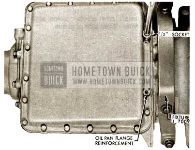
- With transmission upside down, remove twenty oil pan bolts (1/2 ” socket), oil pan flange reinforcement and oil pan.
1958 Buick Flight Pitch Dynaflow Oil Pan
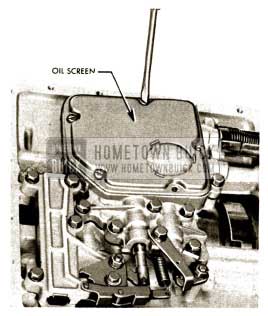
- Remove five oil screen screws, remove screen.
1958 Buick Flight Pitch Dynaflow Remove Oil Screen
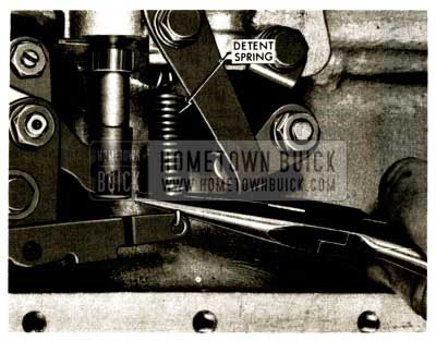
82 . Remove detent spring using needle nose pliers.
1958 Buick Flight Pitch Dynaflow Remove Detent Spring
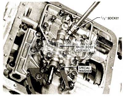
- Remove sixteen valve body bolts and lock washers (1/2″ socket).
NOTE: Special washer on stator control stop bolt.
1958 Buick Flight Pitch Dynaflow Remove Valve Body Bolts
84 . Remove valve body assembly and gasket carefully to avoid dropping valves. Examine gasket for evidence of leakage or improper installation.
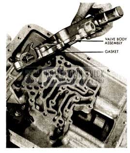
1958 Buick Flight Pitch Dynaflow Remove Valve Body Assembly and Gasket
VALVE BODY DISASSEMBLY
- Use the exploded view of the valve body as a guide during disassembly.
Remove pressure regulator valve spring retainer and spring seat and pin using Tool J-7007 and 7 /16″ wrench.
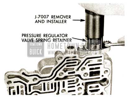
1958 Buick Flight Pitch Dynaflow Remove Valve Body Disssembly
- Remove manual shift valve.
- Remove stator control valve and stop assembly.
- Remove stator modulator valve and springs by rapping valve body against hand.
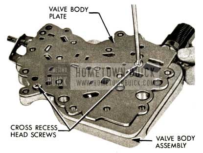
- Remove two valve body cover plate screws with Phillips screwdriver. Remove plate and gasket.
- Examine gasket for evidence of leakage or improper installation.
- Remove front and rear pump check valves and springs.
- Remove pressure regulator guide retaining pin by rapping valve body against hand.
- Remove pressure regulator valve pin guide by rapping valve body against hand.
- Slide out pressure regulator valve.
- While holding in on retainer, remove reverse boost valve retainer pin with needle nose pliers.
- NOTE: Retainer and valve will pop out when pin is removed. Catch valve and retainer to prevent damage.
- Remove reverse boost valve retainer.
- Remove reverse boost valve, spring and limit valve by rapping valve body against hand.
- After thorough cleaning and inspection, assemble valve body as follows.
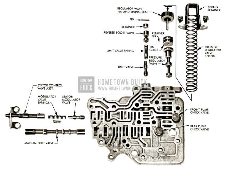
1958 Buick Flight Pitch Dynaflow Valve Body Disassembled
REASSEMBLY OF VALVE BODY
- Use the exploded view as a guide during reassembly.
- Install limit valve, grooved land first. Shake valve body to allow limit valve to reach proper position. The limit valve and the stator modulator valve are the same length and are interchangeable.
- Install reverse boost valve spring, longer than stator modulator valve spring) then install reverse boost valve, narrow land first.
- Insert reverse boost valve retainer.
- Depress reverse boost valve retainer against spring tension and install reverse boost valve retainer pin flush with surface of valve body.
- Insert pressure regulator valve into valve body, small end first.
- Insert pressure regulator valve pin guide so end is flush with edge of valve body. Install pressure regulator valve pin guide retainer pin into valve body and groove of pin guide.
- Insert stator modulator valve into valve body, grooved land first. Shake valve body to allow stator modulator valve to seek proper position.
- Install stator modulator valve springs into valve body. (Shorter than reverse boost spring) Install stator control valve and stop assembly. Install shift control valve, slotted end out.
- Insert pressure regulator valve pin and spring seat into pin guide.
- Install pressure regulator valve spring and spring retainer using Tool 1-7007.
1958 Buick Flight Pitch Dynaflow Remove Valve Body Disssembly
- Before tightening retainer bolts, check clearance between spring seat and retainer with a .010″ feeler gauge. Spring seat must rotate and move in retainer without touching retainer.
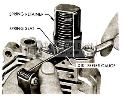
1958 Buick Flight Pitch Dynaflow Retainer Bolts
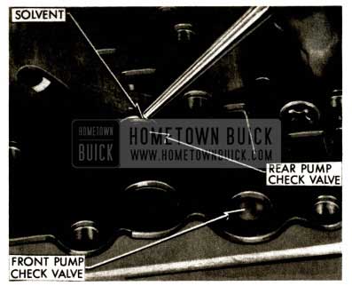
- Install check valve springs and check valves, step sides of valves toward springs.
Be certain that surface of valve body is clear of dirt and has no burrs. Install new valve body plate to valve body gasket. Check and be certain that the pressure regulator valve pin guide retaining pin is in place.
Install valve body plate with two Phillips head screws. Be sure check valves are correctly positioned and operate freely during installation of valve body plate. Be certain that valve body plate gasket lines up with holes in valve body.
1958 Buick Flight Pitch Dynaflow Valve Springs
- Pour small quantity of solvent on each check valve. If valve leaks, it is burred or worn and must be repaired or replaced.
1958 Buick Flight Pitch Dynaflow Rear Pump Check Valve
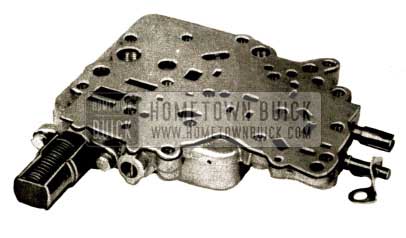
- Completed valve body sub-assembly. If further work is to be done on transmission, set sub-assembly aside.
1958 Buick Flight Pitch Dynaflow Valve Body Sub-Assembly
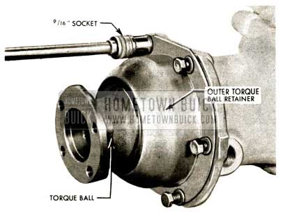
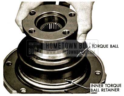
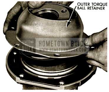
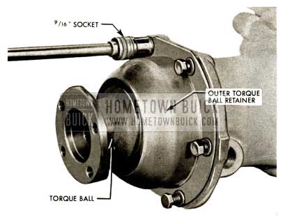
- Remove six torque ball retainer bolts (9 /16″ socket). Remove outer torque ball retainer. Remove torque ball.
1958 Buick Flight Pitch Dynaflow Torque Ball Removal
TORQUE BALL & U-JOINT REMOVAL
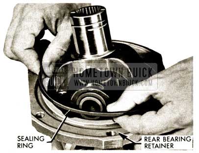
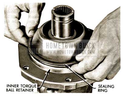
- Remove sealing ring from outside of inner torque ball retainer.
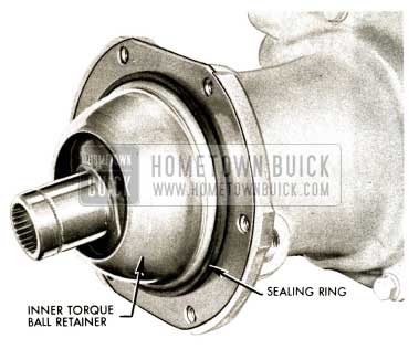
1958 Buick Flight Pitch Dynaflow Remove Sealing Ring
- Remove inner torque ball retainer. Remove sealing ring, inner torque ball retainer to rear bearing retainer.
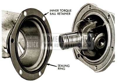
1958 Buick Flight Pitch Dynaflow Remove Inner Torque Ball Retainer
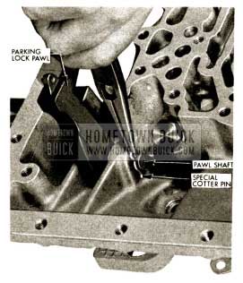
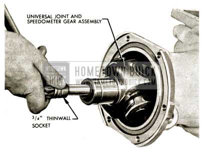
- Engage parking lock pawl. Using a 3/4″ thin wall socket, remove special drilled U-joint bolt, lock washer and plain washer. Remove U- joint and speedo gear assembly.
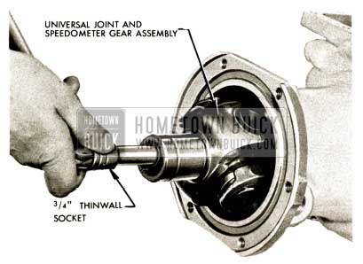
1958 Buick Flight Pitch Dynaflow Parking Lock Pawl
- Remove transmission selector lever shaft nut (5/8″ wrench). Remove selector lever.
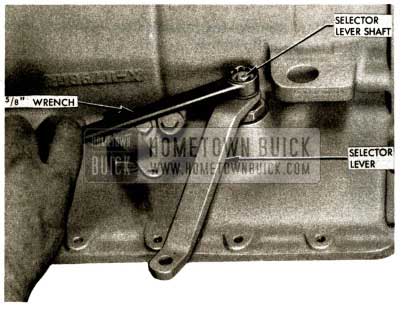
1958 Buick Flight Pitch Dynaflow Remove Selector Lever Shaft
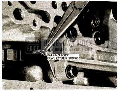
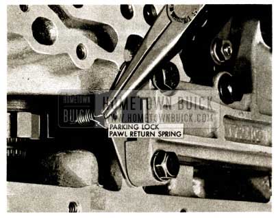
- Remove parking lock pawl return spring using needle nose pliers.
1958 Buick Flight Pitch Dynaflow Remove Parking Lock Pawl
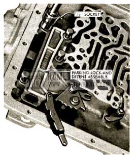
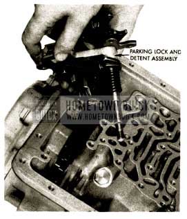
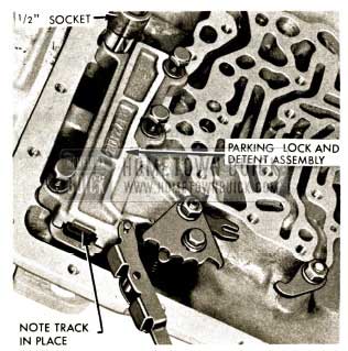
- Remove four parking lock and detent assembly bolts (1/2″ socket).
1958 Buick Flight Pitch Dynaflow Remove Parking Lock Bolts
- Remove parking lock and detent assembly.
1958 Buick Flight Pitch Dynaflow Remove Parking Lock and Detent Assembly
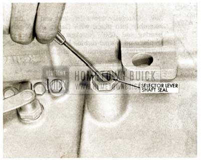
- Remove selector lever shaft seal (pryout).
1958 Buick Flight Pitch Dynaflow Install Selector Shaft Seal
MANUAL CONTROL AND PARKING LOCK DISASSEMBLY, INSPECTION & REASSEMBLY
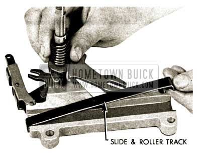
124- Remove slide and roller with slide and roller cover.
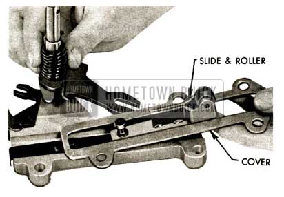
1958 Buick Flight Pitch Dynaflow Install Slide and Roller
- Remove slide and roller track.
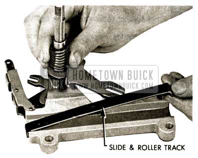
1958 Buick Flight Pitch Dynaflow Install Slide and Roller Track
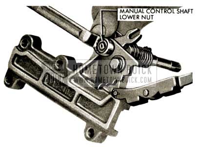
- Remove manual control shaft lower nut (1/2″ wrench).
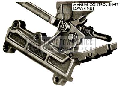
1958 Buick Flight Pitch Dynaflow Install Lower Nut
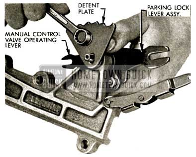
- Remove bolt holding detent plate to manual control valve operating lever. Remove shaft and parking lock lever assembly from parking lock slide body.
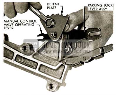
1958 Buick Flight Pitch Dynaflow Assemble Parking Lock
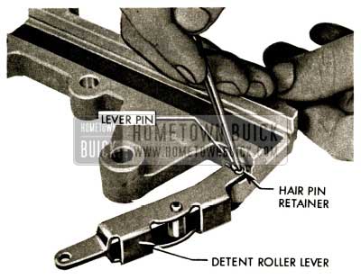
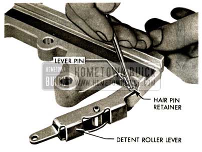
- Remove hair pin retainer from detent roller lever pin, remove pin and roller lever.
1958 Buick Flight Pitch Dynaflow Assemble Roller Lever
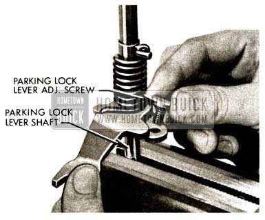
- Clamp lower flats of parking lock lever shaft in vise, rotate lever against spring tension and remove nut from parking lock lever adjusting screw (7/16″ wrench). Remove screw.
1958 Buick Flight Pitch Dynaflow Install Parking Lock Lever Adjusting Screw
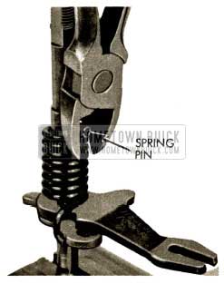
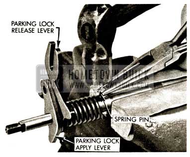
- Rotate lever to release spring tension and pull pin from shaft. Remove spring and parking lock apply lever.
1958 Buick Flight Pitch Dynaflow Spring Pin
REASSEMBLY OF MANUAL CONTROL AND PARKING LOCK
- Assemble spring on shaft with levers as shown in Figure. Reinstall roll pin holding with pliers to start. Use soft jaws on vise to prevent damage to shaft.
1958 Buick Flight Pitch Dynaflow Parking Lock Release Lever
- Clamp lower flats of parking lock lever shaft in vise, raise and rotate lever against spring tension and install parking lock lever adjusting screw, lock washer and nut. Do not tighten.
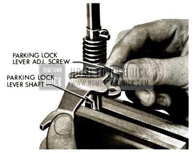
1958 Buick Flight Pitch Dynaflow Parking Lock Lever Adjustment Screw
- Assemble roller lever to slide body with pin and hair pin retainer.
1958 Buick Flight Pitch Dynaflow Remove Hair Pin Retainer
- Assemble parking lock and shaft lever assembly to parking lock slide body. Assemble manual valve operating lever, then detent plate on shaft. (Bolt hole slot in detent plate must be closest to left side of detent plate). Install bolt, flat washer and lock washer. (detent plate to manual control valve operating lever) (7 /16″ wrench).
1958 Buick Flight Pitch Dynaflow Remove Parking Lock Lever Bolt
- Install lower nut and lock washer on manual control shaft (1/2″ wrench).
1958 Buick Flight Pitch Dynaflow Remove Manual Control Shaft Lower Nut
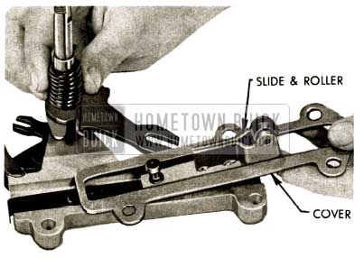
- Install slide and roller track in groove of slide body.
1958 Buick Flight Pitch Dynaflow Remove Slide and Roller Track
- Install slide and roller and cover into slide body, rotate shaft and move slide and roller so slot in lever engages pin of slide and roller. If further work is to be done on transmission, set completed sub assembly aside.
1958 Buick Flight Pitch Dynaflow Manual Remove Slide and Roller
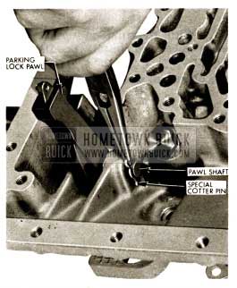
- If the parking lock pawl or the pawl shaft require replacement, follow the instructions below. Otherwise, swing the pawl out of the way .
Remove spring pin from parking lock pawl shaft. Slide shaft rearward. Remove pawl.
1958 Buick Flight Pitch Dynaflow Install Parking Lock Pawl
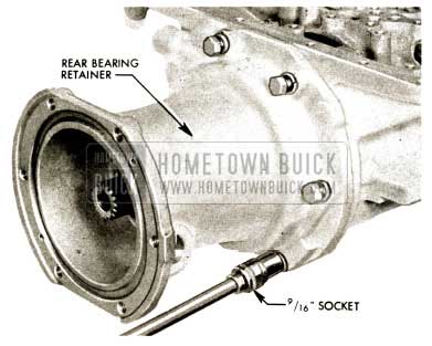
REAR BEARING RETAINER REMOVAL
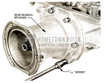
- Remove six rear bearing retainer bolts (9/16″ socket).
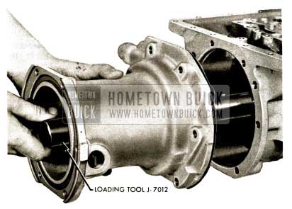
IMPORTANT: A spacer and shim forward of the rear bearing ride on a shoulder of the output shaft. This spacer and shim will fall off the output shaft and lodge in the rear bearing retainer between the rear bearing and rear oil pump if loading Tool J-7012 is not used.
1958 Buick Flight Pitch Dynaflow Remove Loading Tool
- Insert loading Tool J-7012 in end of output shaft to prevent spacer and shim from falling. Hold loading tool forward while sliding rear bearing retainer and rear oil pump assembly away from case. Shim and spacer will be transferred from output shaft to loading tool. Leave loading tool in rear bearing retainer assembly. Remove gasket.
If rear bearing or rear oil pump are not to be inspected or repaired, leave loading tool in place and set assembly aside. Otherwise, proceed with rear bearing retainer – rear oil pump disassembly.
1958 Buick Flight Pitch Dynaflow Assemble Rear Bearing Retainer
REAR BEARING RETAINER -REAR OIL PUMP DISASSEMBLY, INSPECTION & REASSEMBLY
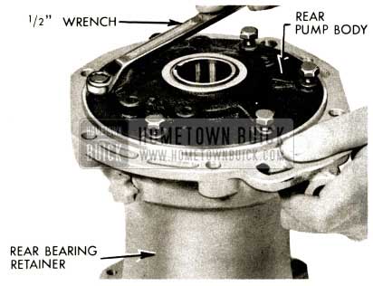
- Remove six rear oil pump body to rear bearing retainer bolts (1 /2″ wrench).
1958 Buick Flight Pitch Dynaflow Rear Bearing Retainer
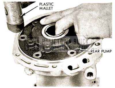
- Remove loading Tool J-7012 from rear bearing retainer assembly. Separate oil pump body from rear bearing retainer by supporting assembly by oil pump and tapping rear bearing retainer with plastic mallet. Remove rear oil pump and gasket.
1958 Buick Flight Pitch Dynaflow Remove Loading Tool J-7012
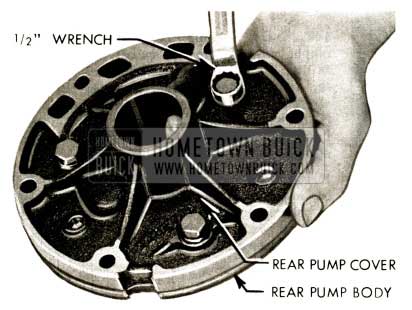
- Remove three rear oil pump cover to body bolts (1/2″ wrench).
1958 Buick Flight Pitch Dynaflow Rear Oil Pump Cover
- Separate rear pump cover from body by rapping two dowels with drift if necessary.
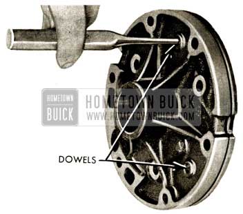
1958 Buick Flight Pitch Dynaflow Remove Rear Pump Cover
- Remove rear pump gears by lifting straight up. Examine gears.
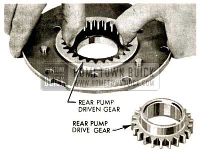
1958 Buick Flight Pitch Dynaflow Remove Rear Pump Gears
145A. Examine rear pump body bushing. If worn or scored, drive bushing out using J-7013-1 Handle and J-7273-8 Remover.
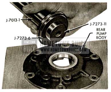
1958 Buick Flight Pitch Dynaflow Install Rear Pump Body Bushing
145B. Install new rear pump body bushing using J -7013-1 Handle and J -7273-6-11 Installer. (Counterbore on 6 toward handle.)
1958 Buick Flight Pitch Dynaflow Install Rear Pump Body Bushing
- Check rear pump gear end clearance using support sleeve and dial indicator. Zero indicator on pump body then slide plunger to rest on gears, one at a time, reading should be between .001″ and .002″ less.
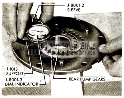
1958 Buick Flight Pitch Dynaflow Rear Pump Gear End Clearance
- Check drive gear clearance using feeler gauge. Should be no more than .006″ to .012″.
1958 Buick Flight Pitch Dynaflow Drive Gear Clearance
- Check driven gear clearance using feeler gauge. Should be between .0045″ and .012″.
1958 Buick Flight Pitch Dynaflow Driven Gear Clearance
- With gears installed in rear pump body, align dowel pins and assemble rear pump body to cover with three bolts. Torque to 20 ft . lbs. with 1/2″ socket.
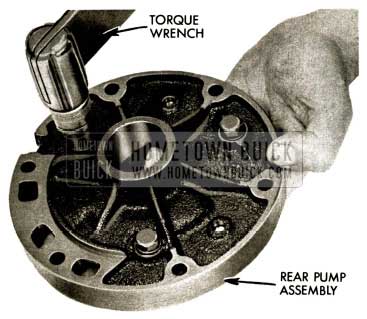
1958 Buick Flight Pitch Dynaflow Assemble Rear Pump Body
- Remove select fit shims and spacer from rear bearing retainer.
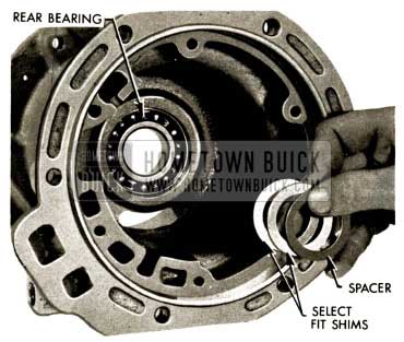
1958 Buick Flight Pitch Dynaflow Remove Select Fit Shims
- Using screwdriver, pry out rear bearing lock.
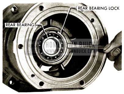
1958 Buick Flight Pitch Dynaflow Rear Bearing Lock
- Support rear bearing retainer web with chamfered edge of Tool J-7077 and drive out bearing with hammer and drift. Drive from front to rear. The rear bearing races are damaged during removal and the bearing must not be reused.
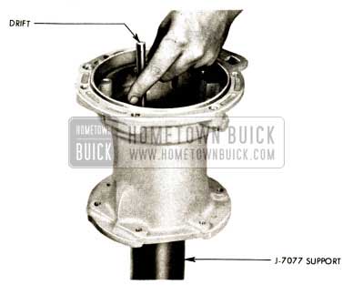
1958 Buick Flight Pitch Dynaflow Tool J-7077
- Support rear bearing retainer web on chamfered edge of Tool J-7077 and install new bearing using J -7013-1 Handle and J -7013-24
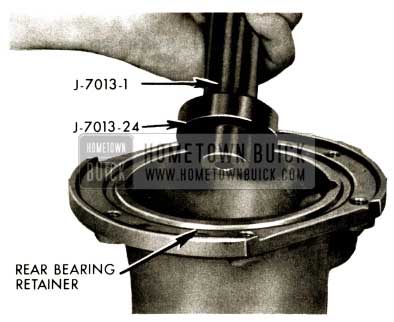
1958 Buick Flight Pitch Dynaflow Support Rear Bearing Retainer
- Install rear bearing lock behind rear bearing by prying in on one end of ring with screw driver in drain slot and forcing ring down into groove with another screwdriver. Use care to avoid dropping aluminum chips in rear bearing. Do not install rear oil pump until output shaft end play has been checked and brought within limits.
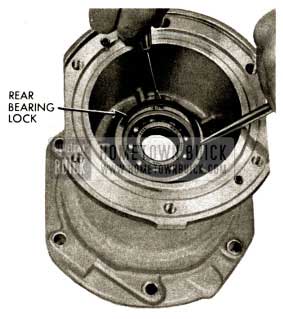
1958 Buick Flight Pitch Dynaflow Install Rear Bearing Lock
OUTPUT SHAFT ASSEMBLY REMOVAL
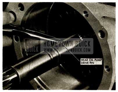
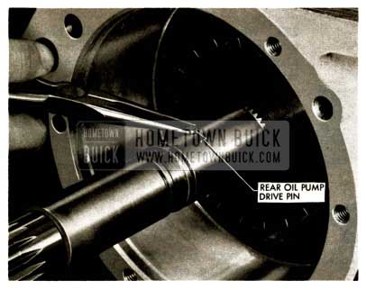
- Remove rear oil pump drive pin using needle nose pliers.
1958 Buick Flight Pitch Dynaflow Rear Oil Pump Drive Pin
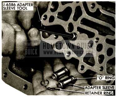
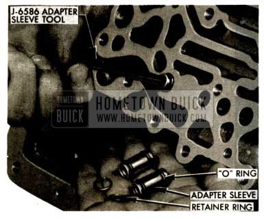
- Remove three of the four adapter sleeves with retaining rings and “O” rings using J-6586 Adapter Sleeve Tool.
1958 Buick Flight Pitch Dynaflow Remove Adapter Sleeves
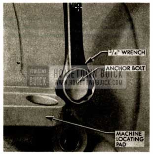
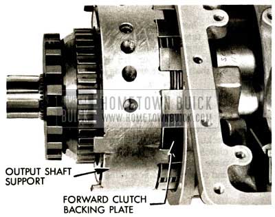
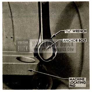
- Remove one of the two output shaft support anchor bolts forward of right rear machine locating pad (outside case). Use 3/4″ wrench.
1958 Buick Flight Pitch Dynaflow Remove Output Shaft Support Anchor Bolts
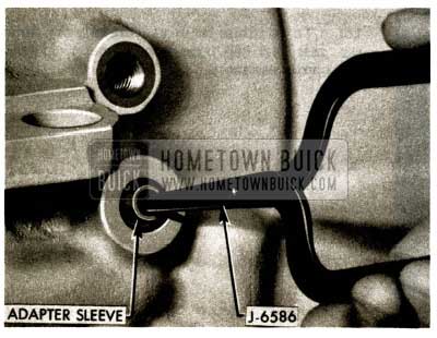
- Remove fourth adapter sleeve with 0 rings at oil cooler return pipe location. (Next to anchor bolt location).
NOTE: No retaining ring.
1958 Buick Flight Pitch Dynaflow Remove Adapter Sleeve
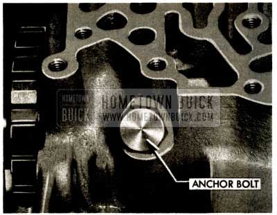
- Remove second output shaft support anchor bolt forward of ratchet wheel (inside case)(3/4″ socket).
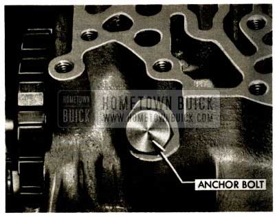
1958 Buick Flight Pitch Dynaflow Install Inner Anchor Bolt
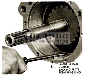
- Remove retaining ring behind grade retard clutch backing plate using a screw driver to pry ring out of groove in transmission case.
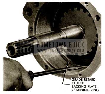
1958 Buick Flight Pitch Dynaflow Install Grade Retard Clutch Backing Plate
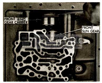
- To facilitate removal, carefully pry front sun gear and hub from front planet ring gear and carrier assembly.
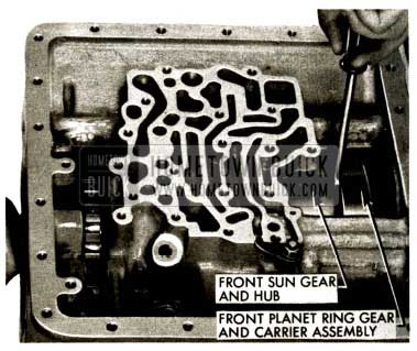
1958 Buick Flight Pitch Dynaflow Front Planet Ring Gear
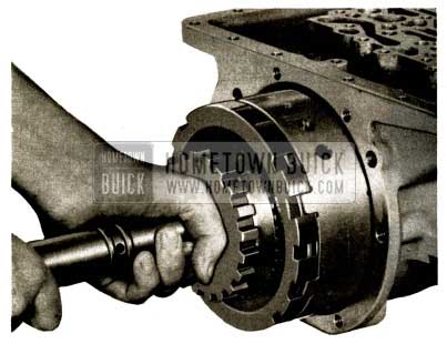
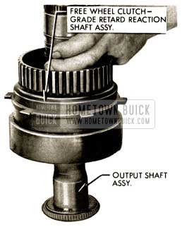
- Install slide hammer J-2619-A and Adapter J-8117 in rear end of output shaft and hammer sharply to start grade retard clutch, output shaft support, forward clutch, free wheel clutches, rear planet set and front sun gear out of transmission case.
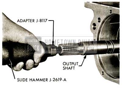
1958 Buick Flight Pitch Dynaflow Install Slide Hammer J-2619-A
- After assembly has been moved part way with slide hammer, remove slide hammer and lift assembly from case and set on bench.
1958 Buick Flight Pitch Dynaflow Remove Slide Hammer
- Remove first turbine shaft and front planet set – neutral clutch assembly. Remove needle thrust bearing and cupped race (front planet ring gear carrier to reaction flange hub.) This bearing and race may have been removed with front pump assembly.
NOTE: First turbine shaft may have been removed with output shaft.
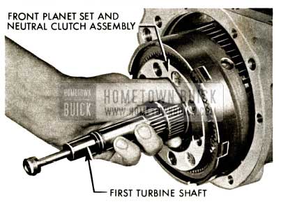
1958 Buick Flight Pitch Dynaflow Remove First Turbine Shaft
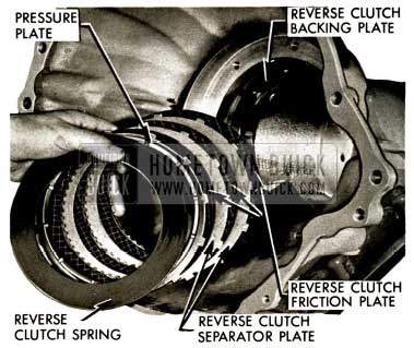
- Remove reverse clutch spring, pressure plate, and clutch plates.
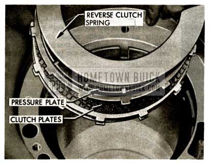
1958 Buick Flight Pitch Dynaflow Remove Reverse Clutch Spring
- Inspect reverse clutch backing plate and if necessary to replace, drive out upper case to reverse clutch backing plate dowels.
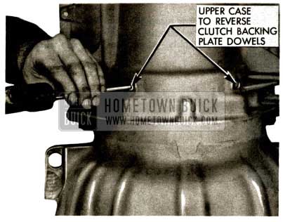
1958 Buick Flight Pitch Dynaflow Inspect Reverse Clutch Backing Plate
- Drive out lower case to reverse clutch backing plate dowels.
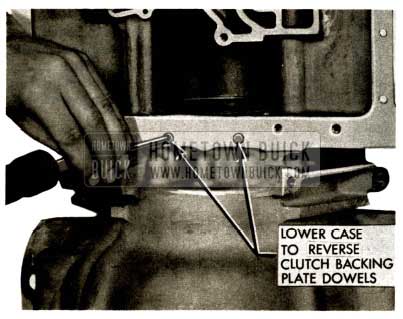
1958 Buick Flight Pitch Dynaflow Lower Case to Reverse Clutch Backing Plate
- Using a hard wood block to rest on rear of backing plate, drive backing plate out toward front of transmission.
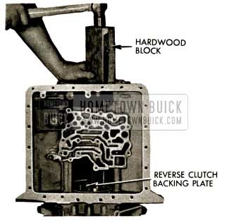
1958 Buick Flight Pitch Dynaflow Reverse Clutch Backing Plate
- Drive new backing plate into position using a hard wood block.
Align dowel holes in backing plate with dowel holes in transmission case and install new dowels.
CAUTION: Dowels must not extend beyond the inner surface of the backing plate.
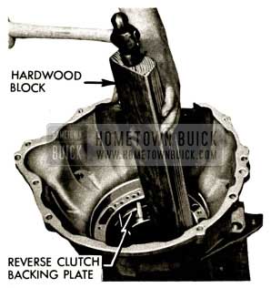
1958 Buick Flight Pitch Dynaflow Install Reverse Clutch Backing Plate
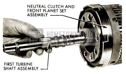
NEUTRAL CLUTCH AND FRONT PLANET SET – FIRST TURBINE SHAFT ASSEMBLY – DISASSEMBLY, INSPECTION & REASSEMBLY
- Slide first turbine shaft rearward out of neutral clutch and front planet set assembly if it was not removed with output shaft.
1958 Buick Flight Pitch Dynaflow Neutral Clutch
- Examine and if necessary, remove and reinstall four new oil rings, two butt type rings and two hooked rings on first turbine shaft. Set first turbine shaft aside.
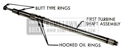
1958 Buick Flight Pitch Dynaflow First Turbine Shaft Assembly
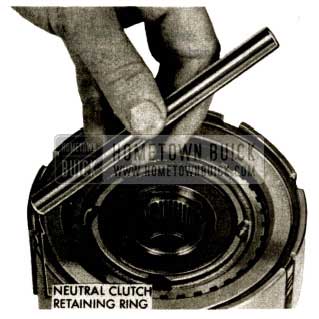
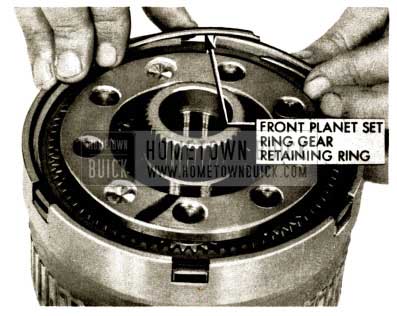
- Remove front planet set ring gear retaining ring using a screwdriver to pry out of groove in front ring gear carrier.
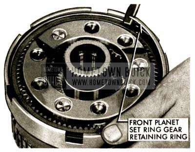
1958 Buick Flight Pitch Dynaflow Remove Front Planet Set Ring Gear Retaining Ring
- Remove ring gear from ring gear carrier.
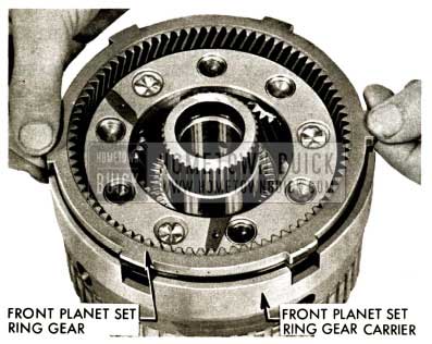
1958 Buick Flight Pitch Dynaflow Remove Ring Gear
- Invert assembly and remove ring gear carrier from neutral clutch and front planet set assembly.
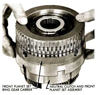
1958 Buick Flight Pitch Dynaflow Remove Ring Gear Carrier
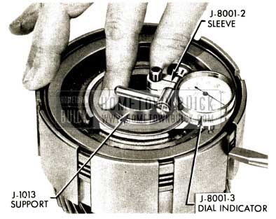
- Check clearance in neutral clutch pack. Use a dial indicator with support J-1013 resting on hub. Set plunger of dial indicator on backing plate. Force plate pack down with fingers and note reading. Force plate pack up with screwdriver between neutral clutch spring snap ring and pressure plate and note clearance. Should be between .010″ and .060″.
1958 Buick Flight Pitch Dynaflow Neutral Clutch Pack
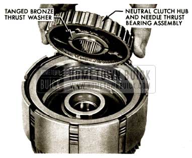
- Remove neutral clutch hub, needle thrust bearing assembly and tanged bronze thrust washer from neutral clutch and front planet set assembly.
1958 Buick Flight Pitch Dynaflow Remove Neutral Clutch Hub
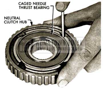
- If necessary to replace, pry out caged needle thrust bearing with small screwdriver.
1958 Buick Flight Pitch Dynaflow Neutral Clutch Hub
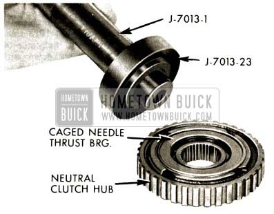
- Install new caged needle bearing in neutral clutch hub using J -7013-1 Handle and J-7013-23.
NOTE : Be certain needle thrust bearing is installed squarely in neutral clutch hub and after installation, rotate race to check for free operation. Race operate freely.
1958 Buick Flight Pitch Dynaflow Install Caged Needle Bearing
- Remove retaining ring from neutral clutch backing plate to front planet set carrier using a screwdriver to pry ring out of groove in front planet set carrier.
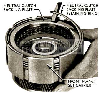
1958 Buick Flight Pitch Dynaflow Remove Neutral Clutch Retaining Ring
- Remove neutral clutch backing plate, clutch plates and pressure plate from front planet set carrier.
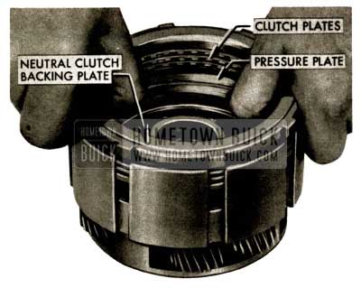
1958 Buick Flight Pitch Dynaflow Remove Neutral Clutch Backing Plate
- Remove retaining ring (neutral clutch spring to front planet set carrier) using a screwdriver to pry ring out of groove in front planet set carrier.
NOTE: This retaining ring is the same as the neutral clutch backing plate retaining ring.
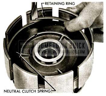
1958 Buick Flight Pitch Dynaflow Remove Neutral Clutch Spring
- Remove neutral clutch spring from front planet carrier.
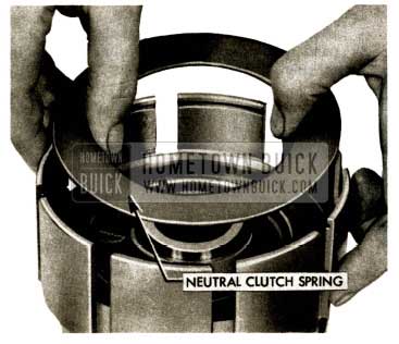
1958 Buick Flight Pitch Dynaflow Neutral Clutch Spring
- Remove neutral clutch piston and seal assembly.
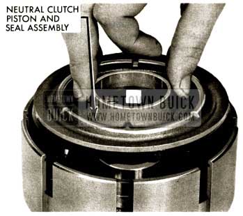
1958 Buick Flight Pitch Dynaflow Remove Neutral Clutch Piston
- Remove neutral clutch piston rubber sealing ring.
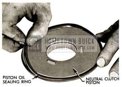
1958 Buick Flight Pitch Dynaflow Remove Neutral Clutch Piston Rubber Sealing Ring
- Examine and if necessary, unhook, expand and remove neutral clutch piston inner oil ring.
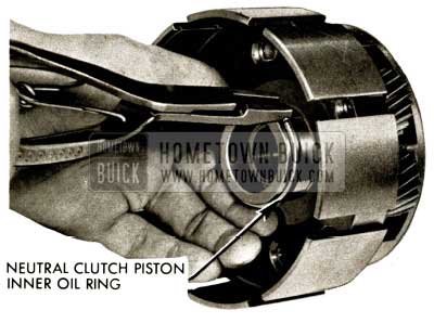
1958 Buick Flight Pitch Dynaflow Neutral Clutch Piston Inner Oil Ring
- Remove needle thrust bearing and thrust bearing race from rear of front planet set carrier. It may be necessary to pry them loose from the suction created by oil. Use two very thin, sharp awls inserted between planet pinion gears and under edge of race.
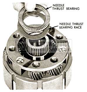
1958 Buick Flight Pitch Dynaflow Remove Needle Thrust Bearing and Thrust Bearing Race
- If necessary to replace, expand and install new neutral clutch piston inner oil sealing ring oh hub of front planet carrier. Hold one end of ring and work other end of ring around to hook.
1958 Buick Flight Pitch Dynaflow Neutral Clutch Piston Inner Oil Ring
- Install new neutral clutch piston sealing ring, lip away from hub.
1958 Buick Flight Pitch Dynaflow Remove Neutral Clutch Piston Rubber Sealing Ring
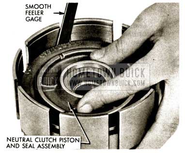
- Lube and install neutral clutch piston and seal in bore of front planet set carrier using a smooth feeler gauge to aid entry of seal lip.
Use care to avoid damage to seal.
1958 Buick Flight Pitch Dynaflow Install Neutral Clutch Piston
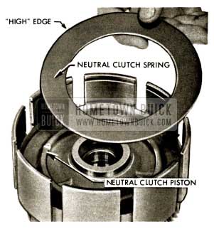
- Install neutral clutch spring on top of piston outer “high” edge up.
1958 Buick Flight Pitch Dynaflow Install Neutral Clutch Spring
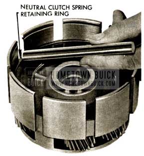
- Install neutral clutch spring retaining ring by starting one end into groove and using plastic hammer and drift to force remainder of ring into groove.
Note: Neutral clutch spring is under tension when retainer ring is installed.
1958 Buick Flight Pitch Dynaflow Install Neutral Clutch Spring Retaining Ring
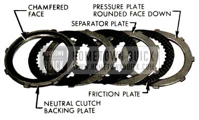
- Install clutch plate pack with rounded face of pressure plate toward spring, then lubricate and install friction plate, separator plate, etc., and chamfered face of clutch backing plate “up” and on top.
NOTE: All clutch plates in neutral clutch pack are flat, three friction plates and two separator plates.
1958 Buick Flight Pitch Dynaflow Install Clutch Plate Pack
- After sticking bronze thrust washer to hub and needle bearing assembly with heavy lube, line up grooves of friction plates and install hub in bore of front planet set carrier (needle bearing up). When neutral clutch hub is correctly installed it will be below chamfered edge of neutral clutch backing plate.
1958 Buick Flight Pitch Dynaflow Remove Neutral Clutch Hub
- Install neutral clutch retaining ring in groove of front planet set carrier above backing plate. Tap solidly into groove with drift.
1958 Buick Flight Pitch Dynaflow Install Neutral Clutch Retaining Ring
- Check clearance in neutral clutch pack. Use a dial indicator with support J-1013 resting on hub. Set plunger of dial indicator on backing plate. Force plate pack down with fingers and note reading. Force plate pack up with screwdriver between neutral clutch spring snap ring and pressure plate. Note reading. Difference between two readings (clearance) should be between .010″ and .060″.
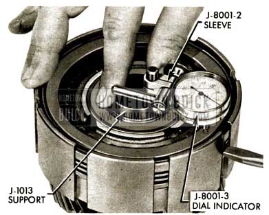
1958 Buick Flight Pitch Dynaflow Dial Indicator Support J-1013
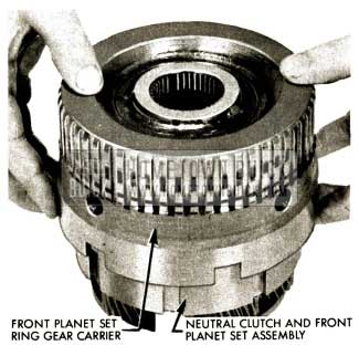
- Install front ring gear carrier over neutral clutch and carrier assembly. Grasp carefully under the carrier and invert.
1958 Buick Flight Pitch Dynaflow Install Front Ring Gear Carrier
- Mesh ring gear with planet gears and install in carrier with tangs up.
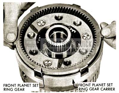
1958 Buick Flight Pitch Dynaflow Mesh Ring Gear
- Install ring gear retaining ring and tap into groove of ring gear carrier.
1958 Buick Flight Pitch Dynaflow Install Ring Gear Retaining Ring
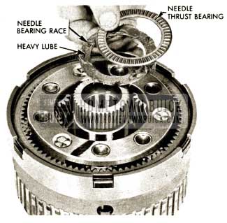
- Apply heavy lube to needle bearing race and needle bearing (1 3/4″ X 2 1/2″) (Between front sun gear and front planet carrier). Insert race first, then bearing into bore of front planet set. Press down to seat .
NOTE: No race on top of needle bearing. Front of front sun gear acts as race. This bearing and race are smaller in I.D. and O.D. than the bearings used in the turbine build-up. Care should be used to avoid interchanging these bearings and races.
1958 Buick Flight Pitch Dynaflow Needle Bearing Race
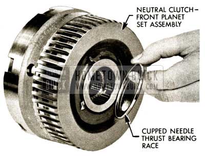
- Invert assembly, examine and if necessary, apply heavy lube to new cupped needle bearing race and install on front planet ring gear carrier.
NOTE: This race may have remained on rear of stator reaction shaft when transmission was disassembled.
1958 Buick Flight Pitch Dynaflow Neutral Clutch Front Planet Set Assembly
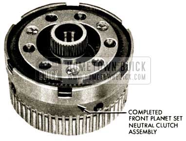
- Front planet set -neutral clutch assembly. Set completed assembly aside.
1958 Buick Flight Pitch Dynaflow Front Planet Set
DISASSEMBLY, INSPECTION & REASSEMBLY OF OUTPUT SHAFT ASSEMBLY
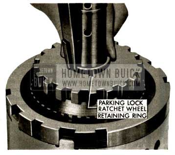
- Expand and remove parking lock ratchet wheel retaining ring.
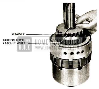
1958 Buick Flight Pitch Dynaflow Remove Parking Lock Ratchet Wheel
- Slide grade retard clutch backing plate and clutch pack off clutch hub and output shaft.
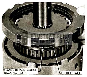
1958 Buick Flight Pitch Dynaflow Grade Retard Clutch Backing Plate
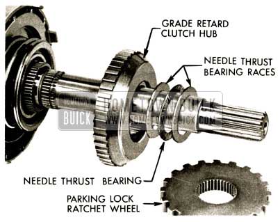
- Remove parking lock ratchet wheel and grade retard clutch hub. Needle thrust bearing and two thrust bearing races will come off output shaft with grade retard hub.
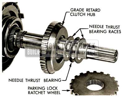
1958 Buick Flight Pitch Dynaflow Install Grade Retard Clutch Hub
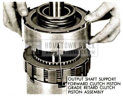
- Slide output shaft support, forward clutch piston and grade retard piston assembly off output shaft.
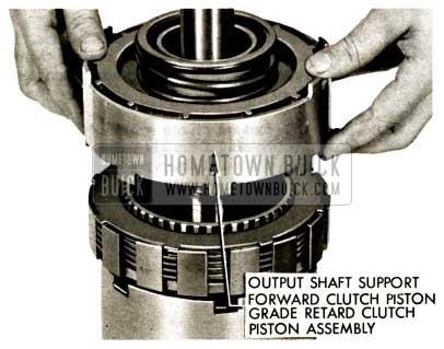
1958 Buick Flight Pitch Dynaflow Install Output Shaft Support Assembly
OUTPUT SHAFT SUPPORT DISASSEMBLY, INSPECTION AND REASSEMBLY
- From side of output support having eight lugs, remove forward clutch piston spring retainer ring using snap ring pliers and J-2590-12 and 14.
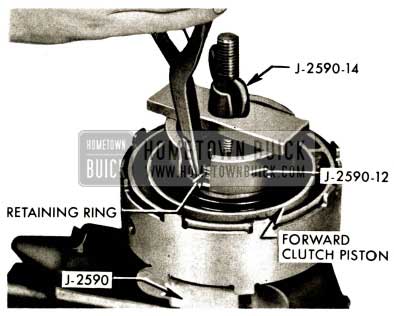
1958 Buick Flight Pitch Dynaflow Install Forward Clutch Spring
OUTPUT SHAFT SUPPORT ASSEMBLY
- Remove tool , retainer ring, spring seat, spring and forward clutch piston from output shaft support.
Note : Note wide chamfer on I.D. of piston.
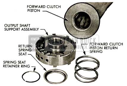
1958 Buick Flight Pitch Dynaflow Forward Clutch Piston Return Spring
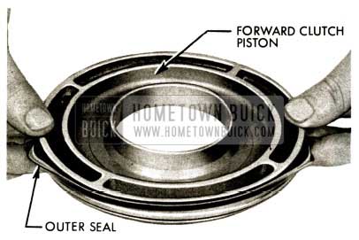
- Remove rubber outer seal from forward clutch piston.
1958 Buick Flight Pitch Dynaflow Install Rubber Sealing Ring
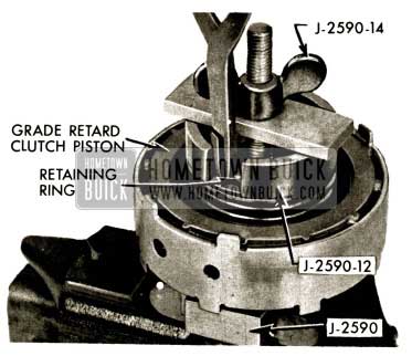
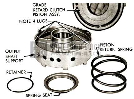
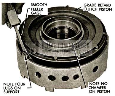
- From side of output support having four lugs, remove grade retard spring retainer ring using snap ring pliers and Tool J-2590-12 and 14.
1958 Buick Flight Pitch Dynaflow Install Grade Retard Clutch Spring
- Remove tool, retainer ring, spring seat, spring and grade retard piston.
NOTE: No chamfer on piston or on bore.
1958 Buick Flight Pitch Dynaflow Remove Output Shaft Support
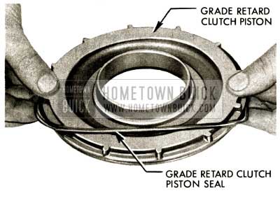
- Remove rubber oil sealing ring from grade retard piston.
1958 Buick Flight Pitch Dynaflow Install Rubber Sealing Ring on Grade Retard Piston
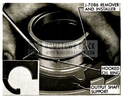
- Examine and if necessary to replace forward clutch piston inner oil ring; assemble Tool J-7086 so forward clutch inner oil ring is forced solidly into groove. Press down the movable arm of Tool J-7086 and pry free end of the hooked oil ring out with screwdriver. Release movable arm of tool, expand and remove hooked oil ring from output shaft support.
1958 Buick Flight Pitch Dynaflow Examine Forward Clutch Piston Inner Oil Ring
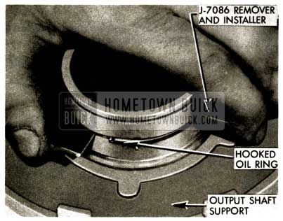
- Expand and install new forward clutch piston inner oil ring in groove of output shaft support. Assemble Tool J-7086 to compress ring in groove. Press on movable arm of Tool J-7086, free end of ring will snap into hooked position.
1958 Buick Flight Pitch Dynaflow Install Forward Clutch Piston Inner Oil Ring
- Examine and if necessary to replace grade retard clutch piston inner oil ring, remove and replace using Tool J-7086 and method used on forward clutch ring.
1958 Buick Flight Pitch Dynaflow Examine Forward Clutch Piston Inner Oil Ring
- Using hook made of stiff wire pull out lube pressure regulator spring retainer, spring and ball.
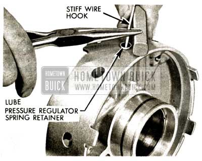
1958 Buick Flight Pitch Dynaflow Lube Pressure Regulator Spring Retainer
- Examine ball. If worn or scored, install new ball in lube pressure hole of output shaft support, then spring, then retainer, small hole down.
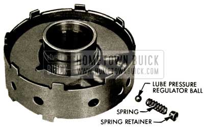
1958 Buick Flight Pitch Dynaflow Lube Pressure Regulator Ball
- Using a plastic or rawhide mallet, drive lube pressure regulator spring retainer flush with surface of support to .010″ below.
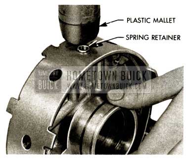
1958 Buick Flight Pitch Dynaflow Plastic Mallet
- Install new rubber sealing ring on forward clutch piston. (Forward clutch piston has wide chamfer in bore)
1958 Buick Flight Pitch Dynaflow Install Rubber Sealing Ring
- Lube and use smooth edge feeler gauge to hold lip of rubber ring down while inserting piston assembly into output shaft support.
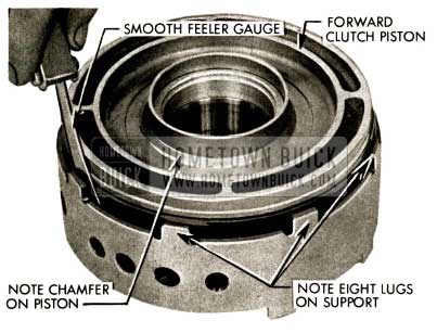
1958 Buick Flight Pitch Dynaflow Smooth Feeler Gauge
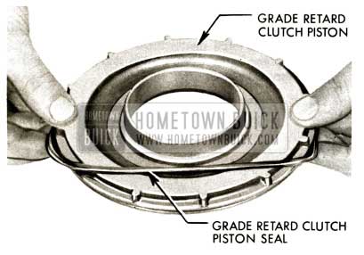
- Install new rubber sealing ring on grade retard piston.
1958 Buick Flight Pitch Dynaflow Remove Rubber Oil Sealing Ring
- Lube and use smooth edged feeler gauge to hold lip of rubber ring down while inserting piston assembly into output shaft support.
1958 Buick Flight Pitch Dynaflow Lubricate Smooth Edged Feeler Gauge
- Install forward clutch spring, retainer and snap ring using Tool J-2590-12 and 14, and snap ring pliers.
NOTE: Spring, retainer and snap ring are interchangeable with grade retard spring, retainer and snap ring.
1958 Buick Flight Pitch Dynaflow Install Forward Clutch Spring
- Install grade retard clutch spring, retainer and snap ring using Tool J-2590-12 and 14 and snap ring pliers.
Set completed output shaft support assembly aside.
1958 Buick Flight Pitch Dynaflow Install Grade Retard Clutch Spring
- Slide forward clutch backing plate and clutch pack off forward clutch hub and output shaft.
1958 Buick Flight Pitch Dynaflow Slide Forward Clutch Backing Plate
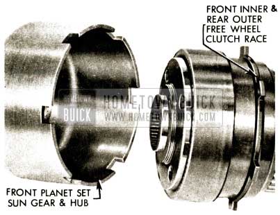
- Separate front planet set sun gear and hub from tangs of front inner and rear outer free wheel race by prying with a screwdriver. Remove sun gear and hub.
1958 Buick Flight Pitch Dynaflow Front Planet Set Sun Gear and Hub
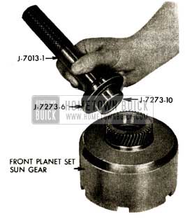
225A. Examine front sun gear bushing. If worn or scored, drive bushing out using J-7013-1 Handle and J-7273-10 Remover.
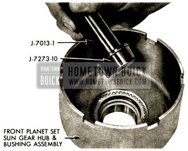
1958 Buick Flight Pitch Dynaflow Examine Front Sun Gear Bushing
225B. Install new front sun gear bushing using J-7013-1 Handle and J-7273-6-10 Installer. (Counterbore on 6 toward 10.)
1958 Buick Flight Pitch Dynaflow Install Sun Gear Bushing
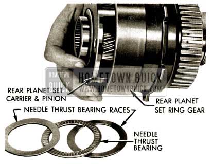
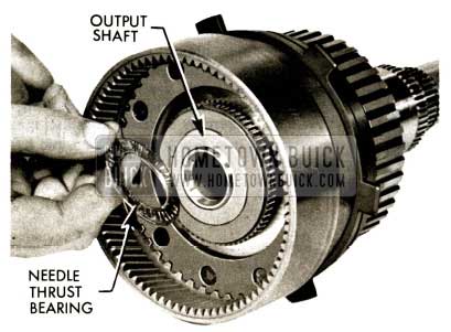
- Remove rear planet set carrier needle thrust bearing and two thrust bearing races from hub of carriers. Grasp carrier and slide carrier and planet assembly out of rear planet set ring gear. it may be necessary to pry to start out.
1958 Buick Flight Pitch Dynaflow Insert Rear Planet Set
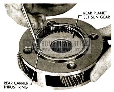
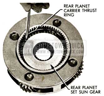
- Pry rear carrier thrust ring out of groove in carrier. Remove ring.
1958 Buick Flight Pitch Dynaflow Rear Carrier Thrust Ring
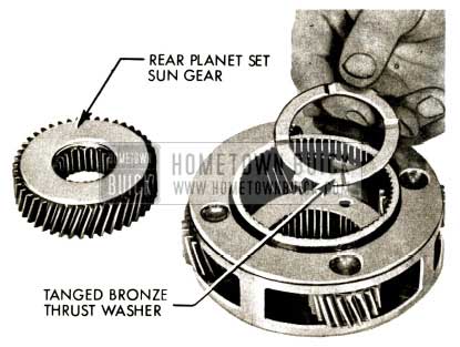
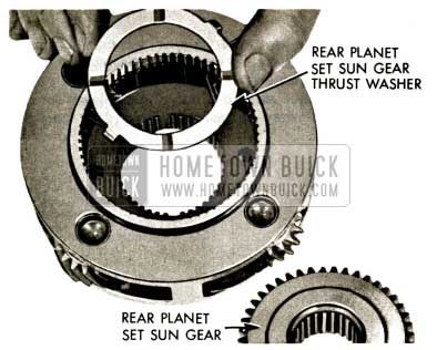
- Remove rear planet set sun gear and tanged bronze thrust washer (between rear sun gear and rear planet carrier) from rear planet set.
1958 Buick Flight Pitch Dynaflow Remove Rear Planet Set Sun Gear
- Examine and if necessary to replace, apply heavy lube to new rear planet set sun gear thrust washer. Position in carrier, tangs down, in holes of carrier. Install sun gear either end up.
1958 Buick Flight Pitch Dynaflow Rear Planet Set Sun Gear Thrust Washer
- Install rear carrier thrust ring solidly in groove above sun gear.
Set rear planet set assembly aside.
1958 Buick Flight Pitch Dynaflow Install Rear Carrier Thrust Ring
- Remove needle thrust bearing (between rear sun gear and output shaft) from front of output shaft.
NOTE: No separate needle bearing races used at this point.
1958 Buick Flight Pitch Dynaflow Needle Thrust Bearing Removal
- Slide output shaft forward through grade retard reaction shaft. Needle thrust bearing (between grade retard reaction shaft and output shaft) has no races. Remove needle thrust bearing.
1958 Buick Flight Pitch Dynaflow Slide Output Shaft
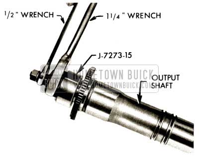
232A. Examine output shaft bushing. If worn or scored, pull bushing usingj-7273-15withoutput shaft in vise equipped with soft jaws. Slip puller into position in output shaft . Expand puller by holding shaft with 1/2 ” wrench and turning 5/8″ nut. Hold shaft with l/2″ wrench and turn, 1 1/4″ nut to pull bushing.
1958 Buick Flight Pitch Dynaflow Examine Output Shaft Bushing
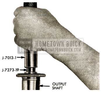
232B. Install new output shaft bushing using J-7013-1 Handle and J -7273-19 Installer.
1958 Buick Flight Pitch Dynaflow Install Output Shaft Bushing
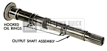
- Examine and if necessary to replace, unhook, expand and remove four hooked oil rings on output shaft .
Expand and install four new hooked oil rings in grooves of output shaft.
Blow compressed air through rear end of output shaft to clean small oil bleed hole and screen in output shaft.
1958 Buick Flight Pitch Dynaflow Replace Hooked Oil Rings
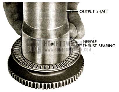
- Examine and if necessary to replace, apply heavy lube to new output shaft to grade retard reaction shaft needle thrust bearing (1 3/4″ I.D. X 2 1/2″ O.D.) and place in position on output shaft.
1958 Buick Flight Pitch Dynaflow Replace Output Shaft
- Expand and remove rear free wheel inner race to grade retard reaction shaft retaining ring.
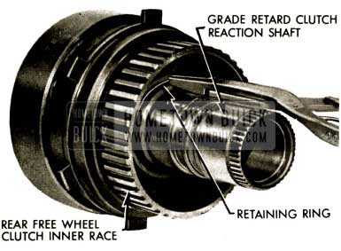
1958 Buick Flight Pitch Dynaflow Remove Rear Free Wheel Inner Race
- Remove rear free wheel clutch inner race thrust washer and spacer (between rear free wheel race and retaining ring). Rotate race clockwise and slide sprag and race out of rear free wheel outer race. Remove and examine sprag.
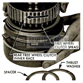
1958 Buick Flight Pitch Dynaflow Remove Rear Free Wheel Clutch Inner Race
236A. Examine rear free wheel clutch inner race bushing. If worn or scored, drive bushing out using J-7013-1 Handle and J-7273-4 Remover.
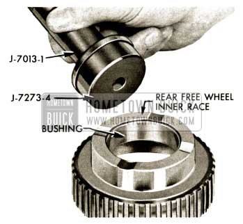
1958 Buick Flight Pitch Dynaflow Examine Rear Free Wheel Clutch Inner Race Bushing
236B. Install new rear free wheel clutch inner race bushing using J -7013-1 Handle and J -7273-5-6. (Counterbore on 6 toward handle.)
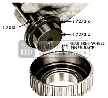
1958 Buick Flight Pitch Dynaflow Install Rear Free Wheel Clutch Inner Race Bushing
- Rotate front inner and rear outer free wheel clutch race clockwise and slide race and sprag out of rear planet ring gear – front free wheel clutch outer race_ Remove and examine sprag.
NOTE: The free wheel clutch springs are identical.
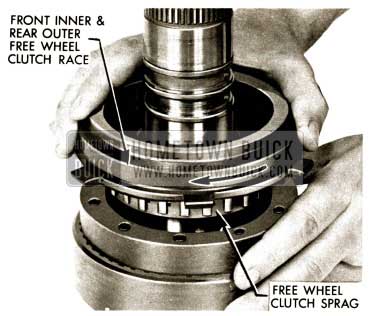
1958 Buick Flight Pitch Dynaflow Front Inner and Rear Outer Free Wheel Clutch Race
237A. Examine front inner and rear outer free wheel clutch race bushing. If worn or scored, drive bushing out using J-7013-1 Handle and J-7273-4 Remover.
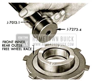
1958 Buick Flight Pitch Dynaflow Examine Front Inner and Outer Free Wheel Clutch
237B. Install new front inner and rear outer free wheel clutch race bushing using J-7013-1 and J-7273-4-6. (Counterbore on 6 toward handle.)
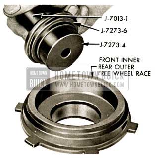
1958 Buick Flight Pitch Dynaflow Install Front Inner and Outer Free Wheel Clutch
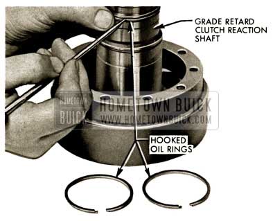
- Examine and if necessary to replace, unhook, expand and remove three oil rings from grade retard reaction shaft. Expand and install three new oil rings in grooves of grade retard reaction shaft, hook ends.
1958 Buick Flight Pitch Dynaflow Replace Oil Rings
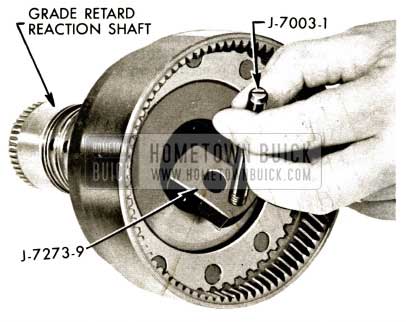
238A. Examine front grade retard reaction shaft bushing. If worn or scored, assemble J -7003-1 Guide Pin to J-7273-9 Remover. Tilt remover to assemble behind front bushing.
1958 Buick Flight Pitch Dynaflow Examine Front Grade Retard Reaction Shaft Bushing
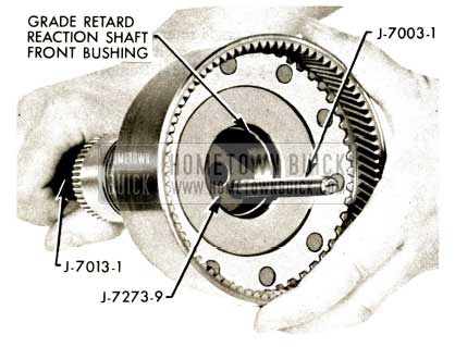
238B. Insert J-7013-1 Handle through rear of reaction shaft to enter J-7273-9 Remover.
1958 Buick Flight Pitch Dynaflow Insert J-7013-1 Handle
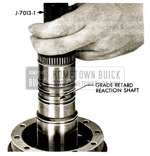
238C. Drive out bushing.
1958 Buick Flight Pitch Dynaflow Drive Out Bushing
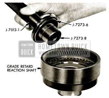
238D. Install new grade retard reaction shaft front bushing using J-7013-1 Handle and J-7273-6-8. (Counterbore on 6toward handle.)
1958 Buick Flight Pitch Dynaflow Install Grade Retard Reaction Shaft Front Bushing
238E. Examine grade retard reaction shaft rear bushing. If worn or scored, drive out bushing using.J-7013-1 and J-7273-7 Remover.
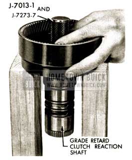
1958 Buick Flight Pitch Dynaflow Grade Retard Reaction Shaft Rear Bushing
238F. Install new grade retard reaction shaft rear bushing using J-7013-1 Handle and J-7273-6-7. (Counterbore on 6toward handle.)
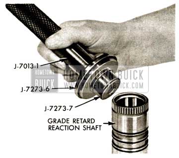
1958 Buick Flight Pitch Dynaflow Install Grade Retard Reaction Shaft
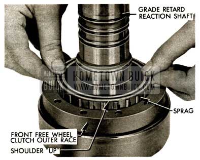
- Slip sprag into front free wheel clutch outer race.
NOTE: Shoulder of sprag up toward reaction shaft.
1958 Buick Flight Pitch Dynaflow Front Free Wheel Clutch Outer Race
- Insert front free wheel clutch inner race into sprag while rotating clockwise. The inner race must rotate freely on clockwise rotation and lock on counterclockwise rotation.
When correctly installed, the front inner free wheel race will be approximately 1/16″ from front outer race. If this dimension is approximately 1/8″ the inner race is hanging up on the bronze strip near the bottom of the sprag assembly.
1958 Buick Flight Pitch Dynaflow Front Free Wheel Clutch Inner Race
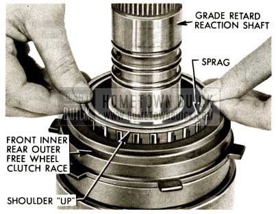
- Insert rear free wheel clutch sprag into rear outer race.
NOTE: Shoulder up toward reaction shaft.
1958 Buick Flight Pitch Dynaflow Insert Rear Free Wheel Clutch Sprag
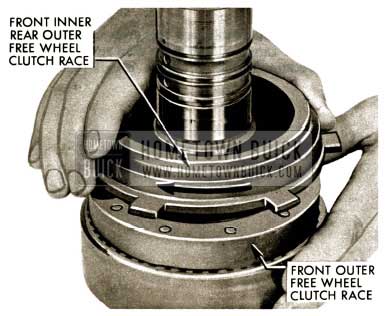
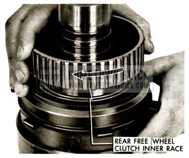
- Insert rear free wheel clutch inner race forward clutch hub into sprag while rotating clockwise. The inner race must rotate freely on clockwise rotation and lock on counterclockwise rotation.
When correctly installed, the rear free wheel inner race should contact front inner rear outer race. If approximately 1/8″ clearance exists rear inner race may be hanging up on bronze strip at bottom of sprag assembly.
1958 Buick Flight Pitch Dynaflow Insert Rear Free Wheel Clutch Inner Race
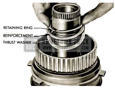
- Assemble new rear free wheel clutch inner race thrust washer first, then reinforcement and retaining ring on grade retard reaction shaft.
1958 Buick Flight Pitch Dynaflow Assemble Rear Free Wheel Clutch Inner Race
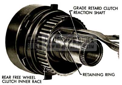
- Expand and install retaining ring solidly in groove of reaction shaft.
1958 Buick Flight Pitch Dynaflow Install Retaining Ring
- Slide free wheel -clutch assembly over output shaft with needle thrust bearing in place.
1958 Buick Flight Pitch Dynaflow Slide Free Wheel Clutch Assembly
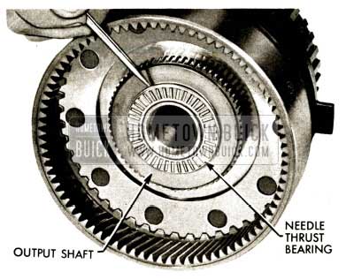
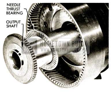
- Examine and if necessary to replace, apply heavy lube to new output shaft to rear planet sun gear needle thrust bearing (13/16″ I.D. X 1 7/8″ O.D.) and set on forward end of output shaft.
NOTE: No races used at this location.
1958 Buick Flight Pitch Dynaflow Replace Output Shaft to Rear Planet
- Insert rear planet set and sun gear assembly into rear planet ring gear assembly.
1958 Buick Flight Pitch Dynaflow Remove Rear Planet Set Carrier Needle Thrust Bearing
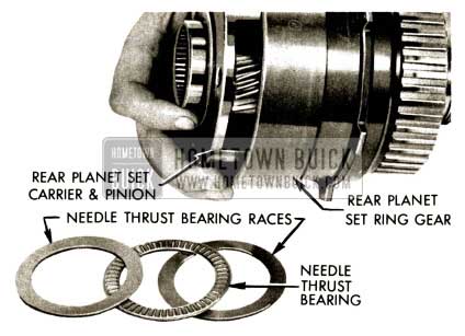
- Apply heavy lube to rear planet set carrier, to front sun gear needle thrust bearing (2” I.D. X 2 3/4″ O.D. ) and two bearing races. Position on hub of carrier.
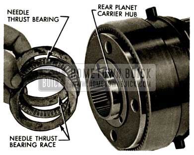
1958 Buick Flight Pitch Dynaflow Rear Planet Carrier Hub
- Install front planet set sun gear and hub over front of rear planet set and free wheel clutch assembly. Do not lift assembly by end of output shaft as thrust washer, etc., may fall out of position. It is best to make this installation with the assembly horizontal and it may be necessary to tap the front sun gear and hub into position.
1958 Buick Flight Pitch Dynaflow Front Planet Set Sun Gear and Hub
- Be sure front planet set sun gear hub extends beyond front inner-rear outer freewheel clutch race tangs as shown in picture.
NOTE: Tangs of front inner-rear outer race do not seat in bottom of slots of sun gear hub.
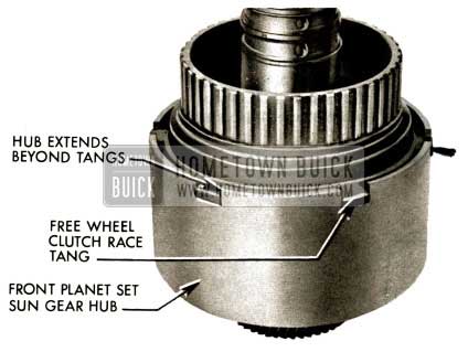
1958 Buick Flight Pitch Dynaflow Front Planet Set Sun Gear Hub
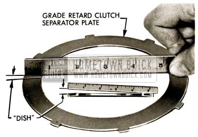
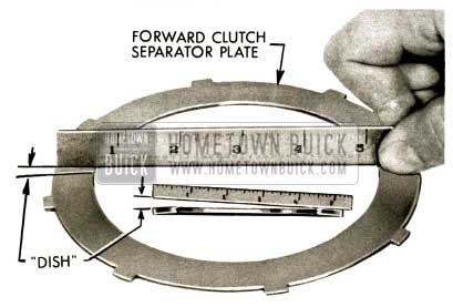
- Examine the forward clutch plates. If they are worn, scored or burned, replace them. The forward clutch friction plates when new are .098″ to .102″ thick.
Check five forward clutch separator plates for “dish” by holding a straight edge against one side of the plate observing the slope of the straight edge. All separator plates must be assembled with “dish” same way. Plates may be assembled dish “up” or dish “down” as long as plates are installed all with dish same way.
1958 Buick Flight Pitch Dynaflow Grade Retard Clutch Separator Plate
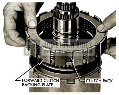
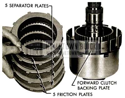
- Install forward clutch backing plate over rear free wheel clutch inner race. Lubricate with Dynaflow oil and install a friction plate next to the backing plate. Engage the tangs of a separator plate in the narrow slots of the backing plate and continue the build -up by alternately assembling a friction plate and a separator plate with all five separator plates “dished” in the same way.
1958 Buick Flight Pitch Dynaflow Install Forward Clutch Backing Plate
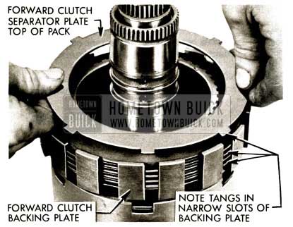
- It is very important to have a friction plate assembled next to the backing plate and a separator plate on top. Serious damage to the forward clutch piston will result if a friction plate is assembled next to the piston.
Tangs of separator plates fit in narrow slots of backing plate.
1958 Buick Flight Pitch Dynaflow Forward Clutch Separator Plate Top
- Lube and install output shaft support assembly on output shaft, eight lugs down and four lugs toward end of output shaft. Engage eight lugs in wide slots of forward clutch backing plate.
1958 Buick Flight Pitch Dynaflow Slide Output Shaft Support
- Install grade retard clutch hub, needle thrust bearing (1 1/2″ I.D. X 2 3/16″ O.D.) and two thrust bearing races, one on each side of needle thrust bearing.
1958 Buick Flight Pitch Dynaflow Remove Parking Lock Ratchet Wheel and Grade Retard
- Slip on parking lock ratchet wheel and expand and install retaining ring solidly in groove of output shaft.
Set completed output shaft assembly aside.
1958 Buick Flight Pitch Dynaflow Parking Lock Ratchet Wheel Retaining Ring
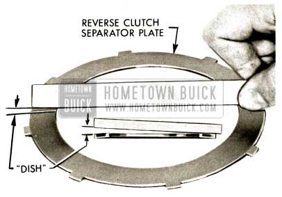
- Check “dish” of two reverse clutch separator plates.
1958 Buick Flight Pitch Dynaflow Reverse Clutch Separator Plate
- with transmission front end “up” lubricate and install a reverse clutch friction plate into reverse clutch backing plate, then a separator “dished” same as first, then last friction plate. Install reverse clutch pressure plate, rounded edge up and reverse clutch spring, center high edge up.
NOTE: Both reverse clutch separator plates must be “dished” same way.
1958 Buick Flight Pitch Dynaflow Install Reverse Clutch Friction Plate
FRONT PUMP – REACTION SHAFT INSTALLATON
- Install new front pump to case gasket in transmission case. Be absolutely certain that gasket holes line up properly. Install two 3/8″- 16 Guide Pins ] -7003 in transmission case, liberally lube rubber seal on front pump assembly with heavy lube and slip front pump and reverse clutch piston assembly into case so that the three closely spaced holes are at bottom of case. Tap the assembly evenly and solidly in position in case with brass drift and plastic hammer.
CAUTION: Never attempt to draw the front pump assembly into position with front pump bolts as transmission case threads will almost certainly be stripped.
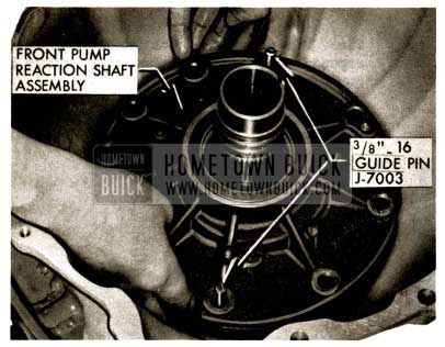
1958 Buick Flight Pitch Dynaflow Front Pump Reaction Shaft Assembly
- Assemble lock washer, new flat washer, and new ”0” ring on ten front pump to case bolts.
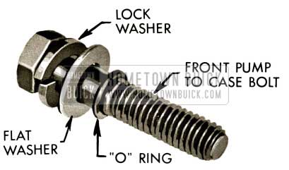
1958 Buick Flight Pitch Dynaflow Assemble Front Pump to Case Bolt
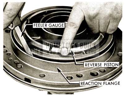
- Install at least two front pump to case bolts to check reverse clutch pack clearance.
Check reverse clutch pack clearance with feeler gauge between any two plates. Clearance should be between .007” and .055″. If clearance is more than .055″, friction plates should be replaced.
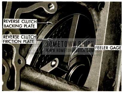
1958 Buick Flight Pitch Dynaflow Install Front Pump to Case Bolts
- Remove guide pins and install all front pump to case bolts. Torque to 30 to 35 ft. lb;. after preliminary tightening by criss-crossing from one bolt to another (9/16″ socket).
1958 Buick Flight Pitch Dynaflow Remove Guide Pins
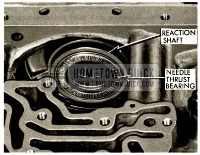
- With transmission upside down, apply heavy lube and install needle thrust bearing (1 3/4″ I.D. x 2 1/2″ O.D.) in cupped bearing race at rear of stator reaction shaft.
1958 Buick Flight Pitch Dynaflow Lubricate Needle Thrust Bearing
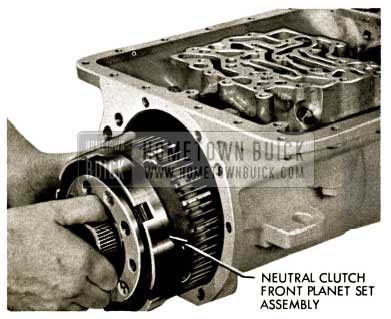
- Install neutral clutch assembly into case. Be certain cupped bearing race is in position on hub of front planet set ring gear carrier (Front of neutral clutch assembly).
1958 Buick Flight Pitch Dynaflow Install Neutral Clutch Assembly
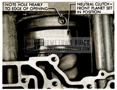
- When installing neutral clutch assembly into reverse clutch pack, rotate neutral clutch assembly to line up splines and allow front planet ring gear carrier assembly hub to seat against needle thrust bearing. Hole in front ring gear carrier will be nearly even with edge of opening in transmission case when assembly is seated against needle thrust bearing.
1958 Buick Flight Pitch Dynaflow Install Neutral Clutch Assembly into Reverse Clutch Pack
- If parking lock pawl and shaft were removed, install parking lock pawl, pawl shaft and retaining pin.
1958 Buick Flight Pitch Dynaflow Remove Spring Pin
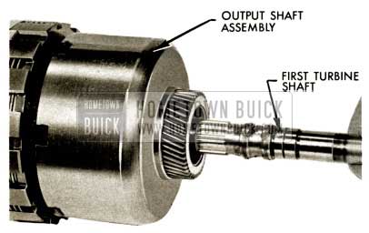
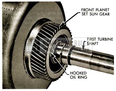
- Lube oil rings on first turbine shaft , rotate shaft to line up splines and insert in output shaft assembly until last oil ring is inside front planet set sun gear.
1958 Buick Flight Pitch Dynaflow Lubricate Oil Rings
- First turbine shaft correctly installed in front end of output shaft assembly.
1958 Buick Flight Pitch Dynaflow First Turbine Shaft Installed
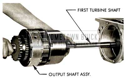
- Start input and output shaft assembly, input shaft first, into rear of transmission case. Guide front of first turbine shaft through neutral clutch assembly.
1958 Buick Flight Pitch Dynaflow Insert Output Shaft Assembly into Turbine
- Push into case till assembly is in position pictured. Check forward clutch backing plate to be certain it is in contact with output shaft support. Be certain clutch plates are properly positioned in slots in backing plate and oil sleeve holes in support are up.
NOTE: Before proceeding with installation, read the following FIVE steps:
1958 Buick Flight Pitch Dynaflow Forward Clutch Backing Plate
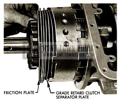
- Check three grade retard clutch separator plates for dish. It makes no difference whether separator plates are installed with dish ”in” or “out” but all must be installed same way.
1958 Buick Flight Pitch Dynaflow Forward Clutch Separator Plate
- Install grade retard clutch separator plate next to piston with center tang of three tangs between lugs of support, then friction plate, separator plate and so on, until three separator plates and three friction plates are installed.
1958 Buick Flight Pitch Dynaflow Install Grade Retard Clutch Separator Plate
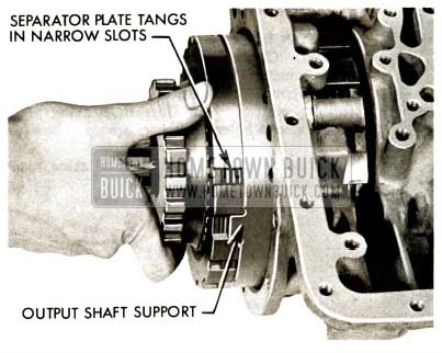
- Install grade retard clutch backing plate with tangs of separator plates in narrow slots and tangs of output shaft support in wide slots. Hold backing plate firmly in contact with output shaft support and slide assembly into position.
CAUTION: Maintain hand pressure forward on grade retard clutch backing plate at all times until assembly is correctly positioned in case and backing plate retainer ring is installed. If backing plate is allowed to separate from support, clutch pack will fall out of position and complete assembly must be removed from case and reassembled according to instructions.
1958 Buick Flight Pitch Dynaflow Install Grade Retard Clutch backing Plate with Tangs
- While installing assembly, it may be necessary to rotate front planet set ring gear or carrier with screwdriver to line up teeth on sun gear with front planet pinions. It is not necessary to force assembly into place. Assembly is correctly positioned in case when grade retard clutch backing plate retaining ring can be installed in groove in case.
1958 Buick Flight Pitch Dynaflow Rotate Front Planet Set Ring Gear
- Install grade retard clutch backing plate retaining ring solidly in groove of case.
1958 Buick Flight Pitch Dynaflow Remove Retaining Ring
- Use smooth punch inserted in anchor bolt hole to line up oil sleeve adaptor holes in support with holes in case. Do not use oil adaptor sleeve holes for this purpose.
Lube and install three adaptor sleeves with new O-rings into valve body portion of transmission case using Tool J-6586. Push down firmly to seat adapter sleeves in output shaft support. Install retainer rings above the O-ring sleeve assemblies using a screwdriver to seat retainer rings against sleeve assemblies.
NOTE: Center adaptor sleeve does not enter case as far as outer two.
1958 Buick Flight Pitch Dynaflow J-6586 Adapter Sleeve Tool
- Lube and install fourth adapter sleeve with new O-rings at oil cooler return line location using Tool J-6586. Oil adapter sleeve retainer ring is not used at this location.
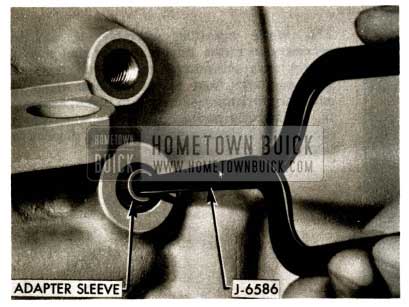
1958 Buick Flight Pitch Dynaflow Install Adapter Sleeve
- Install outer anchor bolt. Torque to 35-40 ft. lbs. (3/4″ wrench).
1958 Buick Flight Pitch Dynaflow Install Outer Anchor Bolt
- Install inner anchor bolt. Torque to 35-40 ft. lbs.
1958 Buick Flight Pitch Dynaflow Remove Second Output Shaft Support Anchor Bolt
- Install rear pump drive pin in output shaft.
NOTE: If rear oil pump was not removed from rear bearing retainer, proceed with Step 287.
1958 Buick Flight Pitch Dynaflow Install Rear Pump Drive Pin
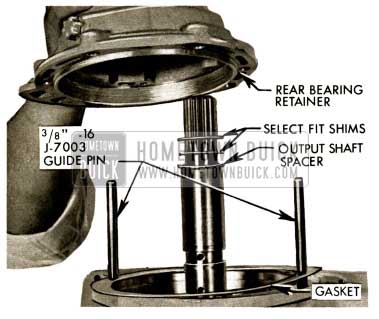
- If rear oil pump and loading tool were removed from rear bearing retainer, install .120″ spacer on output shaft with shims removed from output shaft when transmission was disassembled. Install two guide pins 3/8″ – 16, J-7003, gasket and rear bearing retainer without oil pump.
1958 Buick Flight Pitch Dynaflow Install Spacer on Output Shaft
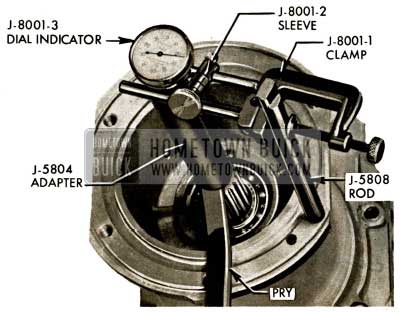
- Check output shaft end clearance with rear bearing retainer bolted to case with at least two bolts as shown and transmission upside down. Tap several times on output shaft to squeeze out lube used on thrust bearings during assembly. Use J-8001-3 Dial Indicator, Tool 5804 threaded into output shaft and Tool J-5808 threaded into rear bearing retainer. Use pry bar under edge of J -5804 to move output shaft. End play should be .015″ to .035″ If output shaft end clearance is less than .015″, remove rear bearing retainer and install a thinner shim on output shaft. If output shaft end clearance is more than .035″, remove rear bearing retainer and install a thicker shim.
1958 Buick Flight Pitch Dynaflow Check Output Shaft Clearance
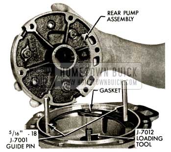
- When output shaft end play has been measured and brought within limits, remove end play gage setup and remove rear bearing retainer from case. Insert loading tool J-7012 in rear of rear bearing retainer through rear bearing. Slip correct shims and spacers from output shaft onto loading tool with shim next to bearing. Install two 5/16” – 18 guide pins J-7001 in rear bearing retainer. Install new rear oil pump to rear bearing retainer gasket; observe openings in pump and openings in rear bearing retainer and assemble rear oil pump to rear bearing retainer with six 5/16″ – 18 bolts. Torque bolts to 15 – 20 ft. lbs.
NOTE: Check gasket for correct position before assembling oil pump to rear bearing retainer.
1958 Buick Flight Pitch Dynaflow Rear Pump Assembly
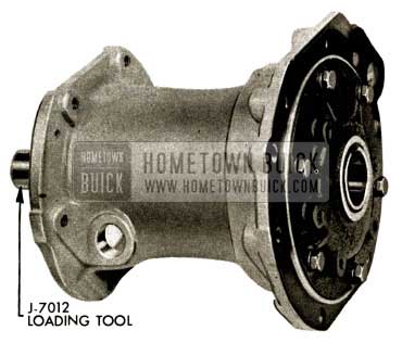
- Completed rear bearing retainer, rear oil pump assembly with loading tool in place.
1958 Buick Flight Pitch Dynaflow Complete Rear Bearing Retainer
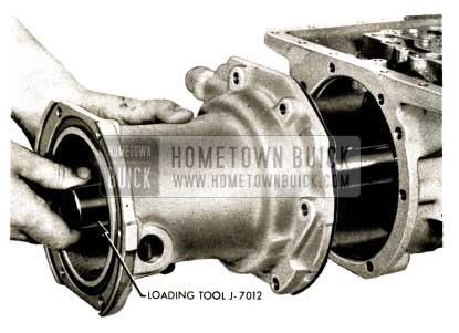
- With rear bearing retainer to case gasket in place assemble rear bearing retainer – rear oil pump assembly to case observing position of slot in oil pump drive gear and driving pin in output shaft. If necessary to turn output shaft to line up pin with oil pump drive gear, turn parking lock ratchet wheel. Hold loading tool forward while sliding bearing retainer onto output shaft to transfer spacer and shims onto output shaft.
1958 Buick Flight Pitch Dynaflow Insert Loading Tool J-7012
- Remove loading tool and install six rear bearing retainer to case bolts. Torque alternately and evenly to 25 – 30 ft. lbs.
1958 Buick Flight Pitch Dynaflow Rear Bearing Retainer Removal
- IF REAR OILPUMPWASNOTREMOVED from rear bearing retainer and loading tool was left in rear bearing retainer, assemble rear bearing retainer to transmission case with new gasket and at least two bolts (9/16″ socket). Observing drive pin and slot in oil pump drive gear, hold loading tool forward during assembly of rear bearing retainer. Check output shaft end clearance as outlined above. If output shaft end clearance is within .015″ to .035″ limits, install remaining bolts and torque all six bolts alternately and evenly to 25 – 30 ft. lbs.
If end clearance is not within limits, rear bearing retainer and rear pump must be removed and end clearance corrected as outlined above.
1958 Buick Flight Pitch Dynaflow Insert Loading Tool J-7012
- Install properly assembled parking lock mechanism to case with four bolts 5/16″-18. Torque bolts to 15 – 20 ft. lm. (1/2″ socket).
1958 Buick Flight Pitch Dynaflow Install Parking Lock Mechanism
- Install parking lock pawl return spring.
1958 Buick Flight Pitch Dynaflow Install Parking Lock Pawl Return Spring
- Engage parking lock pawl. Install U- joint and speedo gear assembly with special drilled U-joint bolt, lock washer and plain washer using 3/4″ thin wall socket. Torque to 50 -55 ft. lbs.
1958 Buick Flight Pitch Dynaflow Engage Parking Lock Pawl
REAR BEARING RETAINER – TORQUE BALL INSTALLATION
- With transmission rear end “up”, use heavy lube and install inner torque ball retainer to rear bearing retainer sealing ring in groove of rear bearing retainer. Install inner torque ball retainer on rear bearing retainer.
1958 Buick Flight Pitch Dynaflow Install Inner Torque Ball Retainer
- Install new sealing ring on outside of inner torque ball retainer.
1958 Buick Flight Pitch Dynaflow Install Sealing Ring
- Liberally lubricate inside of torque ball and install over U – joint and inner torque ball retainer. Position torque ball with drain slot down as transmission is installed in car.
1958 Buick Flight Pitch Dynaflow Lubricate Torque Ball
- Install outer torque ball retainer over torque ball.
1958 Buick Flight Pitch Dynaflow Install Outer Torque Ball Retainer
- Install torque ball bolts using 9/16” socket but do not tighten until transmission is installed in car to facilitate coupling of torque tube and propeller shaft .
1958 Buick Flight Pitch Dynaflow Install Torque Ball Bolts
VALVE BODY INSTALLATION
- With transmission upside down, use new gasket and carefully install valve body assembly. Engage slot in shift lever with slot and pin in manual control valve.
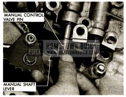
1958 Buick Flight Pitch Dynaflow Manual Control Valve Pin
- Install bolts and lever stop as shown but do not tighten.
NOTE: Special washer under head of lever stop clamp bolt.
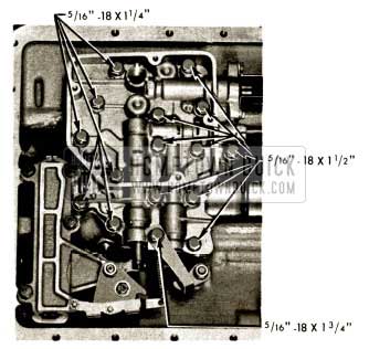
1958 Buick Flight Pitch Dynaflow Install Bolts and Lever Stop
- Torque all valve body bolts to 15 -20 ft. lbs. in sequence shown except two bolts on stator stop (1/2″socket). Check for free operation of shift control valve.
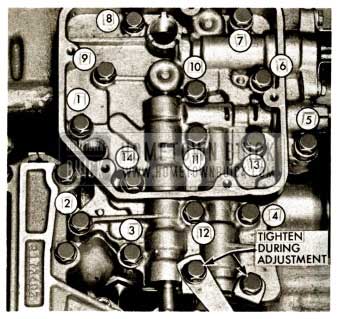
1958 Buick Flight Pitch Dynaflow Valve Body Bolts
STATOR VALVE ADJUSTMENT
- Swing lever stop aside and slip .040″ feeler gauge into position between valve body and valve stop. Press stator valve stop toward valve body and hold in this position by tightening forward bolt as shown (1/2″ wrench).
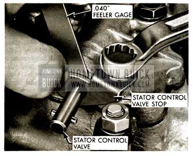
1958 Buick Flight Pitch Dynaflow Stator Control Valve Stop
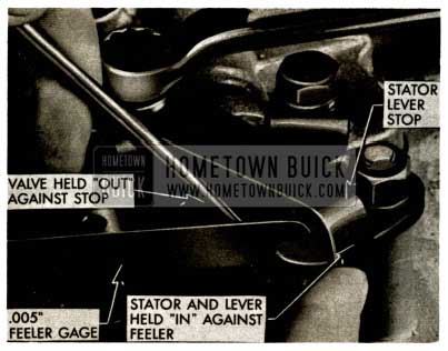
STATOR CONTROL LEVER STOP ADJUSTMENT
- Position lever stop over stator control lever. Place .005 ” feeler gauge between end of stator valve and lever. Hold valve “out” and lever stop against lever. Tighten lever stop clamp bolt in this position (1/2″ wrench).
1958 Buick Flight Pitch Dynaflow Stator and Lever Held-In
- Install detent spring.
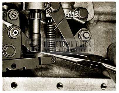
1958 Buick Flight Pitch Dynaflow Install Detent Spring
MANUAL SHIFT VALVE ADJUSTMENT
- With transmission in “Park” position, (detent plate rotated rearward to last notch) loosen manual control valve adjusting bolt (7/16″ wrench), insert 9/64″ drill between inner edge of first land of manual valve and valve body; hold valve “in” toward valve body with drill in position; at same time hold detent lever solidly in notch, and tighten adjusting bolt with valve in this position.
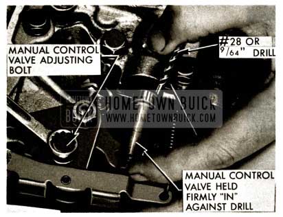
1958 Buick Flight Pitch Dynaflow Manual Control Valve Adjusting Bolt
PARKING LOCK ADJUSTMENT
- With transmission in park position, loosen parking lock adjusting screw – insert .067″ gauge J-7089 between parking lock roller and slide cover. Turn eccentric screw to give -067″ clearance between roller and slide cover. Hold screw in this position and tighten nut (7/16″ wrench). This adjustment insures proper engagement of parking lock pawl.
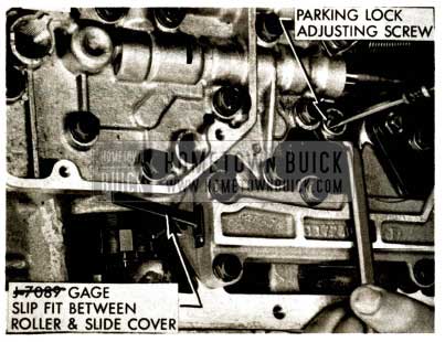
1958 Buick Flight Pitch Dynaflow Parking Lock Adjustment
- ‘Install oil screen and five oil screen screws.
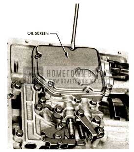
1958 Buick Flight Pitch Dynaflow Install Oil Screen
- Install new oil pan gasket, oil pan, oil pan flange reinforcement and 20 oil pan bolts (1/2″ socket). Torque to 10 – 12 ft. lbs.
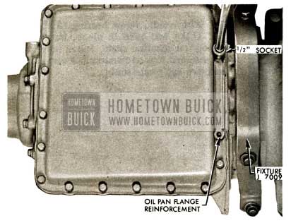
1958 Buick Flight Pitch Dynaflow Install Oil Pan Gasket
- Install selector shaft seal and selector lever.
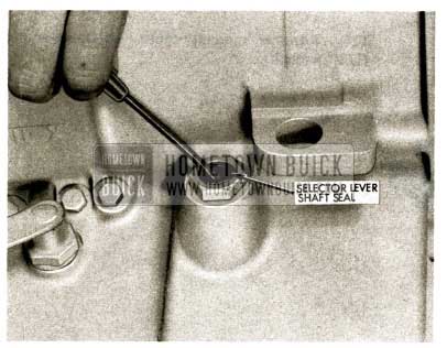
1958 Buick Flight Pitch Dynaflow Remove Selector Lever Shaft Seal
- With transmission front end up, carefully install converter pump in transmission case and rotate to engage lugs of pump hub with front pump drive gear.
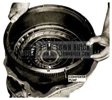
1958 Buick Flight Pitch Dynaflow Install Converter Pump in Transmission
- With needle thrust bearing (2 1/4″ I.D. X 3″ O.D.) and race in place, install stator assembly on reaction shaft. Stator must rotate clockwise and lock on counterclockwise rotation. Press down and rotate stator.
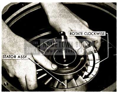
1958 Buick Flight Pitch Dynaflow Install Stator Assembly
- Carefully lower 1st, 2nd and 3rd turbine assembly into place with flanged needle thrust bearing and .050″ (thickest) bearing race held in place on second turbine hub with heavy lube. Rotate turbine assembly to align splines.
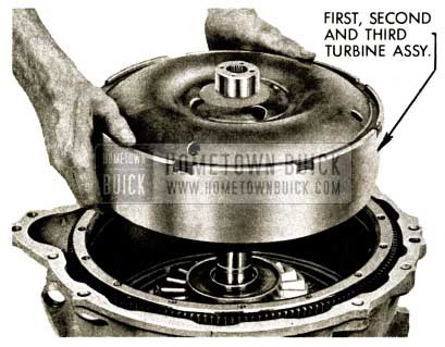
1958 Buick Flight Pitch Dynaflow First, Second and Third Turbine Assembly
- Install new special washer on first turbine shaft. Install and torque first turbine shaft nut to 45 – 50 ft. lbs. using U holder (15/16″ socket).
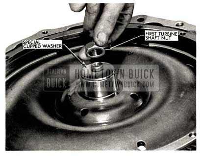
1958 Buick Flight Pitch Dynaflow Remove Special Washer
- Position two select fit plain bearing races on first turbine hub with needle thrust bearing (1 3/4″ I.D. X 2 1/2″ O.D.) between the races.
NOTE: The select fit bearing races are available in .030″, .040″ and .050″ thicknesses.
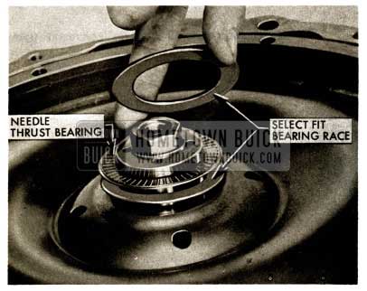
1958 Buick Flight Pitch Dynaflow Select Fit Bearing Race
- Set converter clearance gauge J-5899 in place with small diameter of sleeve up and loosen set screw, push sleeve down to firmly seat, tighten set screw.
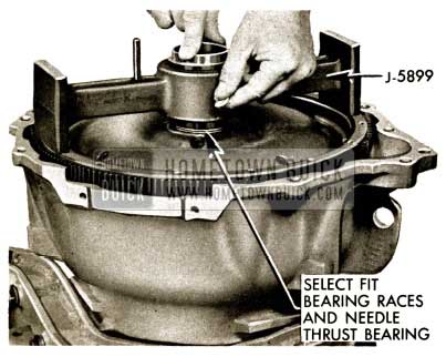
1958 Buick Flight Pitch Dynaflow Set Converter Clearance
- Remove gauge from first turbine hub – invert gauge and place on suitably supported converter pump cover. Assemble dial indicator to post. Place plunger of indicator on gauge sleeve. “Zero” gauge. Loosen sleeve set screw, push sleeve down. Reading on dial indicator is total converter clearance.
If indicator reading is less than .004″ change select fit bearing races to a thinner size. If indicator reading is more than .017″ change select fit races to a thicker size.
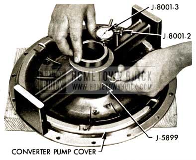
1958 Buick Flight Pitch Dynaflow Remove Gauge
- Install new O-ring on converter pump cover.
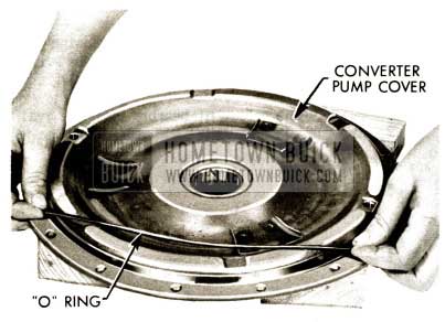
1958 Buick Flight Pitch Dynaflow Install O-Ring
- Assemble converter pump cover in same position as when removed. Install converter pump cover to pump bolts and tighten in sequence as shown. Torque to 35 – 40 ft. lbs.
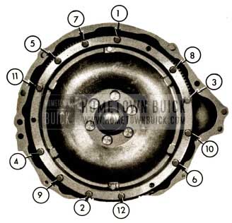
1958 Buick Flight Pitch Dynaflow Assemble Converter Pump Cover
Leave A Comment
You must be logged in to post a comment.