1958 BUICK FLIGHT PITCH DYNAFLOW TEST, INSPECTION, ADJUSTMENT ON CAR
10- 1958 BUICK FLIGHT PITCH DYNAFLOW TEST AND INSPECTION
Road Test
When improper operation of a Dynaflow transmission is reported, time and expense can usually be saved by first making a thorough road test to observe operation in all ranges under appropriate driving conditions. The road test will also serve to thoroughly warm up the transmission, which is required for any tests made in the shop.
The person making the road test should be familiar with the operation and performance of Dynaflow Drive in all ranges so that he will be able to detect any sub-standard condition. The required “feel” of a Dynaflow car can best be acquired by driving through a test routine on a number of cars whose performance is known to be satisfactory. Knowledge of which parts are in operation and which hydraulic controls govern operation in each range is essential to intelligent diagnosis, therefore, a study of Paragraphs 5 through 12 is recommended.
After the transmission has been warmed up to normal operating temperature, thoroughly test operation in all ranges, making tests on steep grades as well as on level road, if possible.
While in “D” range test shifting of the Flight Pitch stator by depressing the accelerator pedal. As the accelerator pedal is depressed beyond half way a change of engine speed accompanied by acceleration pick-up should be noted, indicating that the stator blades are starting to move toward the high angle position.
Shift to Grade Retard “G” range, clutch should engage immediately. A definite braking action should be experienced at car speeds above 15 MPH.
Check for abnormal slip or over-run of the engine on low speed acceleration. With car stopped on level road and brakes released, check for creep when engine is accelerated with transmission in Neutral. Little or no creep should be evident. Check for abnormal creep with engine idling and transmission in each of the driving ranges.
Place transmission in Direct Drive and firmly apply brakes. Snap the throttle open to give engine speed of approximately 1400 RPM and immediately release the accelerator pedal. If the engine returns to idle too slowly, or returns to idle so fast that it either stalls or rolls unevenly, improper throttle linkage and dash pot adjustment is indicated. Rough operation on idle after slow deceleration indicates the need for engine tune-up adjustments.
During all tests, be alert for any unusual or abnormal noises. Carefully note the range, speed and other conditions under which the noise is evident.
Shop Inspection and Test
After the road test described above, a number of shop inspections and tests should be made while the transmission is thoroughly warmed up to operating temperature.
- Check Oil Level.
In every case of a transmission complaint first check the oil level. If oil level is low bring it to proper level and check the effect on operation before doing further work. If oil level is low and the car history indicates oil loss of one pint or more per 1000 miles, or transmission exterior is oily, a thorough inspection for oil leakage should be made as described in Paragraph 10.
- Check Manual Control Linkage.
In cases of improper operation in one or more ranges it is always advisable to check the adjustment of transmission manual control linkage and stator control linkage as described in Paragraph 12.
- Test Oil Pressures in Hydraulic Control System.
When diagnosing almost all cases of improper operation it is necessary to have accurate knowledge of oil pressures in the hydraulic control system. Pressure Test Specification Chart below. These pressure tests should be made before performing any mechanical work.
- Check Engine and Transmission Mountings.
Check the engine and transmission mounting bolts and condition of the rubber mounting bolts and condition of the rubber mountings. Also check for any marks on transmission case or oil pan that would indicate that these parts had been damaged by some obstruction, which might affect alignment of the transmission.
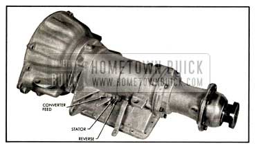
1958 Buick Oil Pressure check locations, right side
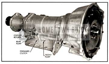
1958 Buick Oil Pressure check locations, left side
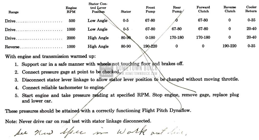
1958 Buick Pressure Test Specifications
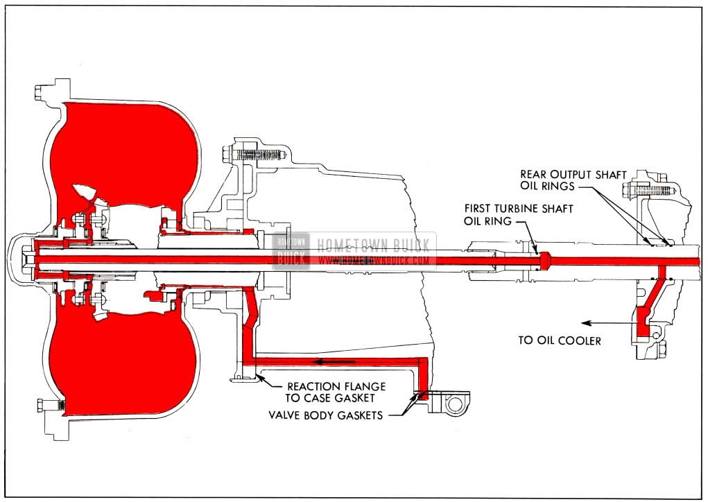
1958 Buick Oil Circuit Through Converter to Oil Cooler
1958 Buick Flight Pitch Stator Valve Oil Supply and Exhaust
1958 Buick Neutral Clutch Oil Supply
1958 Buick Forward Clutch Piston Oil Supply
1958 Buick Reverse Clutch Piston Oil Supply
1958 Buick Grade Retard Clutch Piston Oil Supply
11-DYNAFLOW OPERATIONAL FAULTS AND CAUSES
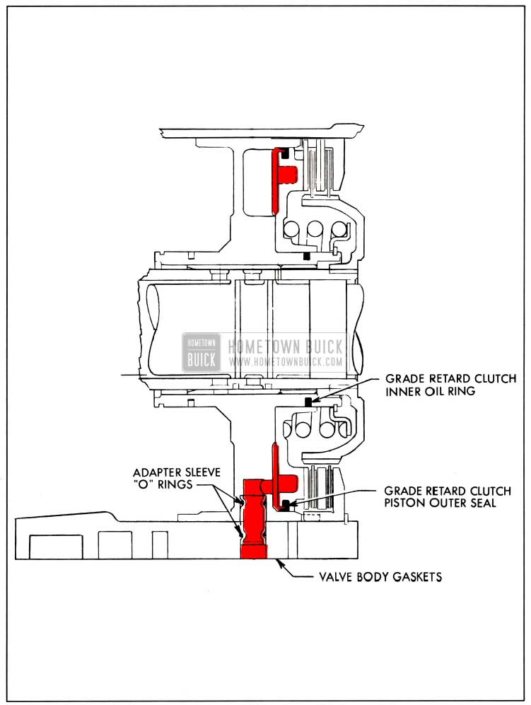
The following illustrations and descriptions may prove of value in Flight Pitch Dynaflow trouble diagnosis. The important oil circuits are illustrated with all sealing points to enable the service man to locate possible points of leakage which should be examined carefully during disassembly.
For Example:
Trouble-Forward Clutch Slips.
Possible points of leakage-(1) Valve body gaskets, (2) Output shaft support adapter sleeves and O-rings, (3) Forward clutch piston inner oil ring, (4) Forward clutch piston outer seal.
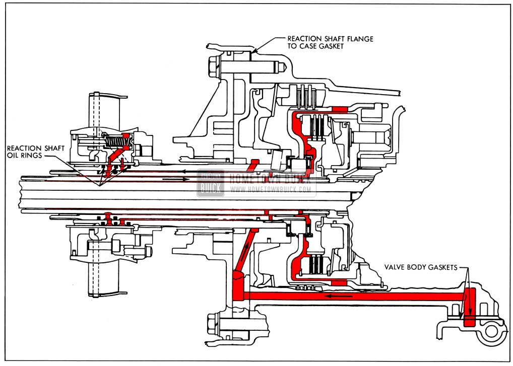
Oil Circuit through Converter to Oil Cooler
Oil at line pressure leaves an exit port of the pressure regulator valve between the first and second lands, passes through the valve body plate and gaskets to the case. Drilled passages in the case carry the oil forward through the reaction flange gasket to the reaction flange. A cast channel and drilled hole in the reaction flange conduct the oil to a counterbored recess in the reaction flange
behind the front pump driving lugs of the converter pump. The oil flows inside the converter pump hub between the hub and stator reaction shaft, through the Flight Pitch stator needle thrust bearing and stator free wheel pilot bearing, into the converter. Oil flows out of the converter between the second and third turbines, forward through drilled holes in the third turbine hub and first turbine disk hub to a counterbored recess in the first turbine disk hub where it is retained by the first turbine shaft nut and special washer. The oil then flows through drilled holes in the first turbine shaft to the hollow center of the first turbine shaft. The oil then flows rearward the length of the first turbine shaft into the first turbine shaft tube which extends into the output shaft. An oil ring on the first turbine shaft tube plug prevents leak back and the oil is directed through the output shaft to a hole between the two rear output shaft oil rings where it exits through the rear pump body and gasket to the rear bearing retainer line to the oil cooler.
Flight Pitch Stator Valve Oil Supply and Exhaust
- Oil at modulated pressure to the stator piston control valve leaves the valve at an exit port between the first and second lands, passes through the valve body plate and both gaskets to the case where drilled passages conduct it through the reaction shaft flange gasket to the reaction shaft flange. Cast and drilled passages in the reaction shaft flange carry the oil to an undercut in the flange which allows the oil to flow through a drilled hole in the reaction shaft to the space between the reaction shaft and the second turbine shaft. The rearmost oil ring on the second turbine shaft prevents the oil from flowing to the rear, so the oil is directed forward to the center oil ring of the second turbine shaft. Just rearward of the center second turbine shaft oil ring a drilled hole in the reaction shaft allows passage to a groove cut in the O.D. of the reaction shaft between the center and rear oil rings. The oil then flows through the rear slot in the stator rear carrier sleeve through a drilled hole in the stator rear carrier to the cavity formed by the stator piston control valve shoulder and the stator rear carrier.
- Exhaust oil through the center of the stator piston control valve leaves the stator rear carrier through a drilled hole connected to the front slot in the stator rear carrier sleeve. From the sleeve the oil enters a groove in the reaction shaft between the front and center oil rings. A drilled hole through the reaction shaft allows the oil to enter a groove and pass through a hole in the second turbine shaft between the front and center oil rings and occupy the space between the second and third turbine shafts. The oil here lubricates the second turbine to third turbine shaft bushing and also flows rearward to a hole in the third turbine shaft to the space between the first and third turbine shafts. The oil then flows rearward to a second hole in the third turbine shaft forward of the neutral clutch hub and behind the front planet set ring gear hub where it exits to lubricate the caged needle thrust bearing in the neutral clutch hub and other components of the neutral clutch.
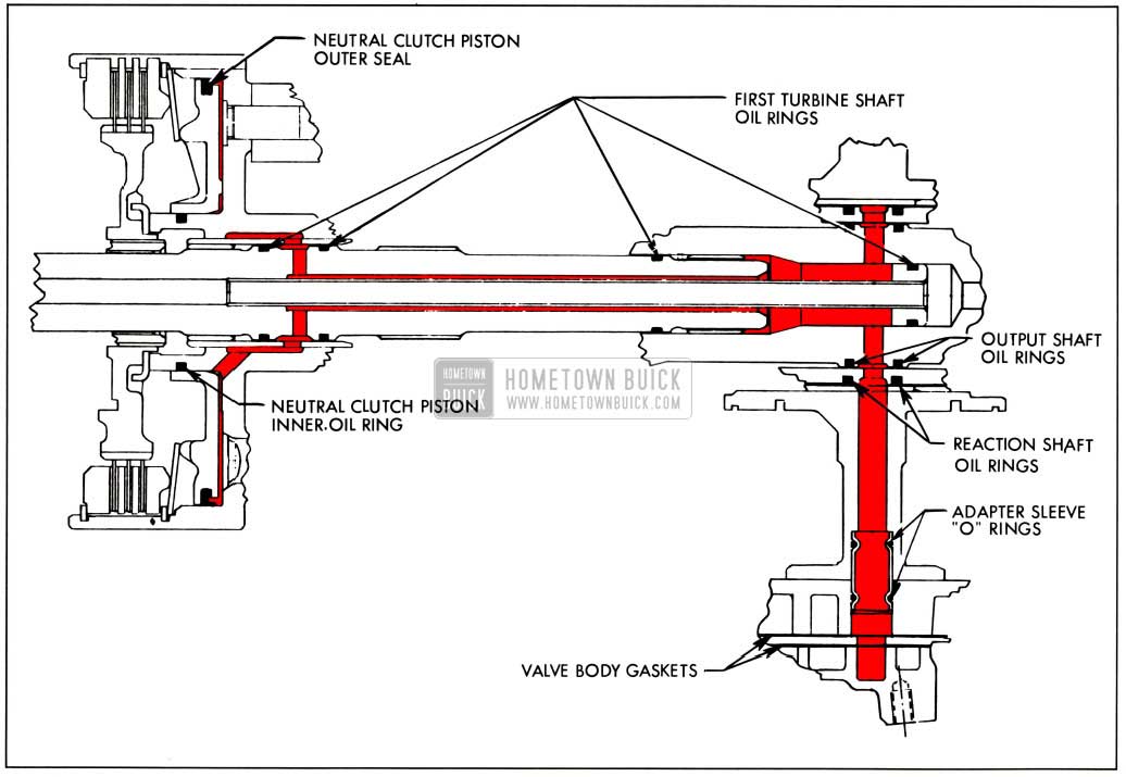
Neutral Clutch Oil Supply
With the selector lever in either Drive “D” range or Reverse “R” range, oil at line pressure leaves the manual control valve, passes through the valve body plate and both gaskets to the case where cast passages direct it through the center oil adapter sleeve and O-rings, to the output shaft support. A drilled hole in the output shaft support directs the oil to a groove and hole in the grade retard reaction shaft between the center and rear oil rings. A groove and hole in the output shaft between the two forward oil rings direct the oil to the space formed by the forward end of the first turbine shaft tube plug and the rear of the first turbine shaft inside the output shaft. The two rear oil rings of the first turbine shaft prevent excessive leakage at this point. The oil then flows forward outside the first turbine shaft tube, between the tube and the first turbine shaft I.D. to a drilled hole in the first turbine shaft where the oil exits to a groove between the two front oil rings of the first turbine shaft. Oil flows from the first turbine shaft groove to a drilled hole and groove in the front planet set carrier to a drilled hole leading to the rear of the neutral clutch piston. Oil is contained in the neutral clutch piston bore by the neutral clutch piston outer rubber seal and the inner oil ring.
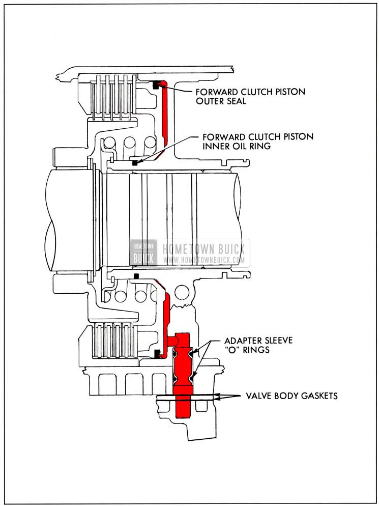
Forward Clutch Piston Oil Supply
With the selector lever in Drive “D” range, oil to the forward clutch piston leaves the control at an exit port between the fourth and fifth lands, passes the valve body plate and both gaskets to enter the case. The oil then passes through an adapter sleeve and O-rings. (Left hand adapter sleeve of the three removed through the valve body portion of the case with the transmission upside down and viewed from the rear.) Leaving the adapter sleeve the oil enters the output shaft support and flows forward through a drilled hole to bear on the forward clutch piston. The oil is contained in this area by the forward clutch piston inner oil ring and outer rubber seal.
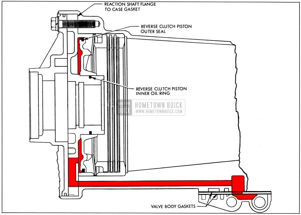
Reverse Clutch Piston Oil Supply
With the selector lever in Reverse “R” range, oil leaves the manual control valve at an exit port between the first and second lands, passes through the valve body plate and both gaskets to the case where a drilled passage conducts it forward, through the reaction shaft flange gasket to the reaction shaft flange. A drilled hole in the rear of the reaction shaft flange allows the oil to enter the cavity in the rear of the reaction shaft flange and bear on the reverse clutch piston. Oil is contained in this area by the reverse clutch piston inner oil ring and outer rubber seal.
Grade Retard Clutch Piston Oil Supply
With the selector lever in Grade Retard “G” range, oil leaves the manual control valve at an exit port between the first and second lands, passes through the valve body plate and both gaskets to enter the case. The oil then passes through an adapter sleeve and O-rings. (The right hand adapter of the three removed from the valve body section of the case with the transmission upside down and viewed from the rear.) Leaving the adapter sleeve the oil enters the output shaft support and flows to the rear through a drilled hole to bear on the grade retard piston. Oil is contained in this area by the grade retard clutch piston inner oil ring and outer rubber seal.
With the results of test and inspection, the causes of improper operation may be determined from the suggestions below.
TROUBLE DIAGNOSIS
Engine Stalls While Decelerating Car with Brakes Applied
- Improper adjustment of throttle dash pot
- Engine not properly tuned
Transmission Oil Foams and Spews Out of Breather Pipe or Filler Pipe
- Transmission over-filled.
If transmission is over-filled, check for blackened condition of oil, indicating leakage of rear axle lubricant into transmission due to defective propeller shaft seals. Check for low oil level in rear axle housing. Correct cause of leakage and completely drain and refill transmission.
- Water in transmission.
Indicated by over-filled condition and caramel color of transmission oil. Water in transmission usually comes from a leaking oil cooler. In this case there may be excessive oil accumulation in top tank of the engine radiator. Correct the cause of leakage, and completely drain and refill transmission.
Car Will Not Move In Any Range Rear Wheels Free
- If car will not move for 1 to 8 minutes after standing over night, park car for several hours with engine stopped. Start engine and check front oil pump pressure. A zero reading until such time as car will move indicates that front pump loses its prime due to excessive clearances. Inspect front pump. If condition has existed for some time it is advisable to inspect clutches for excessive wear due to slippage at low apply pressure.
- Excessively worn neutral clutch plates.
Car Will Not Move In D Only
- Reverse clutch assembly sticking in applied position.
- Forward clutch inoperative or excessively worn.
Car Will Not Move In Reverse Only
- Forward clutch not releasing.
- Reverse clutch inoperative or excessively worn.
Excessive Slip In All Ranges
- Low oil level.
- Manual control linkage improperly adjusted.
- Neutral clutch worn or damaged.
- Forward and reverse clutches slipping.
- Inoperative free wheeling clutches.
- Stator control linkage improperly adjusted.
Excessive Slip In D Only
- Manual control linkage improperly adjusted.
- Faulty free wheeling clutches.
- Forward clutch slipping.
Excessive Slip In Reverse Only
- Manual control linkage improperly adjusted.
- Faulty front free wheeling clutch.
- Reverse clutch slipping.
Car Creeps Forward In Neutral
- Manual control linkage improperly adjusted.
- Neutral clutch or forward clutch not releasing.
- Foreign material collected behind neutral clutch piston.
No Brake Action In G Range
- Inoperative clutch.
- Excessively worn clutch plates.
- Manual control linkage improperly adjusted.
Car Slips at Speeds Above 40 MPH
- Defective neutral clutch.
- Stator control linkage improperly adjusted.
12-FLIGHT PITCH DYNAFLOW LINKAGE ADJUSTMENT
Shift Control Adjustment
If a Dynaflow transmission does not shift properly, the shift control linkage adjustment may easily be checked as follows:
- Move manual control lever carefully until transmission is shifted into its Drive detent position (manual lever will seem to seat).
- Move manual control lever toward Grade Retard (without lifting toward steering wheel) and note how far it moves before contacting stop.
- Move manual control lever until transmission is in Neutral” N” detent position.
- Move manual control lever toward Reverse and note how far it moves before it contacts stop.
- If movement from Drive detent to stop is the same as movement from Neutral detent to stop, shift control linkage is correctly adjusted.
If above check shows linkage to be incorrectly adjusted, adjust linkage as follows:
- With manual control lever in Drive, raise car to gain access to linkage adjusting clevis on lower shift rod.
- Loosen clevis lock nut. Remove cotter pin, clevis pin and spring washer.
- Make sure transmission shift lever is in Drive detent (center position of 5 possible detents).
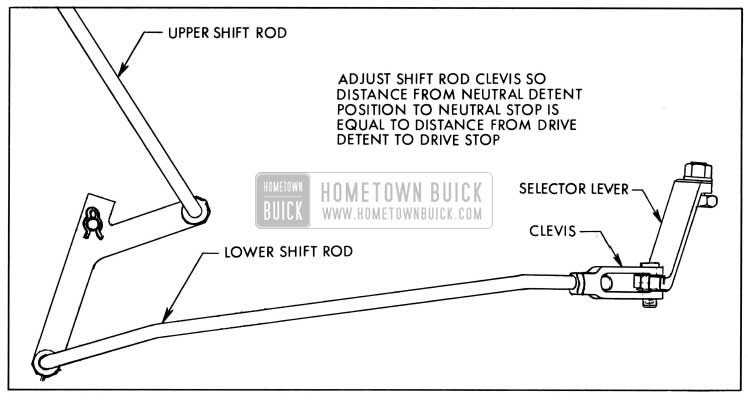
- Move idler lever so that upper shift rod is forced upward as far as possible, then turn clevis until clevis pin will just slip in place without moving transmission shift lever. See Figure 29.
1958 Buick Shift Control Adjustment
Stator Linkage Adjustment
- With throttle in hot idle position, adjust upper stator rod so that ball joint at forward end will just slip freely in stator lever with both stator lever and stator rod pushed rearward.
- Shorten stat stator rod one turn to provide clearance at stop.
- Reconnect ball joint to stator lever and tighten nut.
Leave A Comment
You must be logged in to post a comment.