SECTION 13-F 1958 BUICK CONVERTIBLE TOP (ALL SERIES)
13-16 INTRODUCTION (ALL SERIES CONVERTIBLES)
The top linkage and the 1958 Buick convertible top trim for the 1958 Buick convertibles is very similar to the top linkage and top trim used on the past convertible model. The service operations, except for a few exceptions, are also the same as performed for the past model convertible.
13-17 1958 BUICK SIDE ROOF RAIL WEATHERSTRIPS (ALL SERIES CONVERTIBLES)
The sealing along each 1958 Buick convertible top side roof rail is accomplished by a front, center and rear section of weatherstrip. These weatherstrips are attached to the side roof rails with nuts on the integral studs of the weatherstrip section. In addition, the ends of the weatherstrip sections are secured to the side roof rail with screws.
The procedure below outlines the removal and installation of all three (3) sections of weatherstrip. Each section may be removed and installed separately if desired.
Removal of 1958 Buick Side Roof Rail Weatherstrips
- Lower top halfway.
- Remove weatherstrip attaching screws at ends of each section of weatherstrip.
- Remove screw securing end of front roof rail weatherstrip retainer. Then with a flat bladed tool, carefully break cement bond between front roof rail rear weatherstrip and side of rail front weatherstrip.
- Remove weatherstrip attaching nuts and washers and remove weatherstrips.
- Installation of Side Roof Rail Weatherstrips
- Clean off cement from front and side roof rails to insure clean cementing surfaces.
- Apply an approved weatherstrip cement to forward portion of side roof rail front weatherstrip and to end of front roof rail rear weatherstrip. Then install side roof rail weatherstrip to form “butt” joint with front roof rail weatherstrip.
- Apply a ribbon of body caulking compound along entire length of attaching surface on each side roof rail weatherstrip section just outboard of the integral studs and reverse removal procedure. (See figure 13-94.)
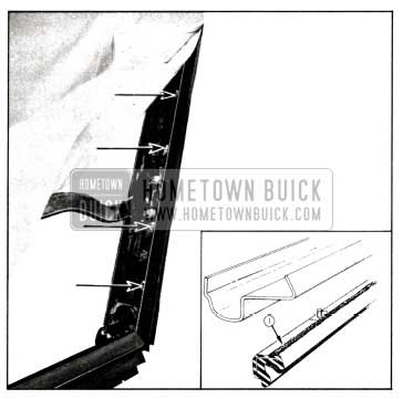
1958 Buick Side Roof Rail Weatherstrip-Convertibles
Clean off excess cement and sealer.
Adjustment of 1958 Buick Side Roof Rail Weatherstrips
- The side roof rail weatherstrip sections may be adjusted inboard or outboard. To adjust, remove attaching screws, loosen attaching nuts and position as desired. Tighten nuts and reinstall attaching screws. If necessary, drill new hole for weatherstrip front attaching screw.
- The side roof rail weatherstrips may also be adjusted downward. To perform this adjustment, loosen weatherstrip as required and insert waterproof cardboard shim between weatherstrip and side roof rail, tighten weatherstrip attaching nuts and reinstall attaching screws.
13-18 1958 BUICK FRONT ROOF RAIL WEATHERSTRIPS (ALL SERIES CONVERTIBLES)
Two weatherstrips of different types are used along the front roof rail. The front weatherstrip is a trim covered %” diameter round rubber which is tacked to the front roof rail trim stick. The rear weatherstrip is a door weatherstrip-type section and is secured to the front roof rail by weatherstrip cement and by the rear edge of a two piece metal retainer.
To remove either weatherstrip, lower the 1958 Buick Convertible top and remove the two piece metal retainer; then remove tacks securing front weatherstrip or break cement bond securing rear weatherstrip. To install weatherstrip, reverse removal procedure. When installing rear weatherstrip, follow cementing instructions outlined for the door weatherstrip.
13-19 1958 BUICK CONVERTIBLE TOP ADJUSTMENTS (ALL SERIES CONVERTIBLES)
The 1958 Buick convertible top linkage consists of three sections of right and left side roof rails and a front roof rail connected together by bolts, hinges, and a series of connecting links and bows. The top linkage is attached to the body at the rear quarter area by a male hinge bolted to an adjustable support. The front roof rail is locked at the windshield header by two cam locks which are an integral part of the two locking handles.
The following information outlines and illustrates procedures which may be used to correct misaligned folding top linkage. To correct some top variations, only a single adjustment is required; other top variations require a combination of adjustments. In conjunction with adjustment of the 1958 Buick Convertible top, it may be necessary to adjust the door, door glass, rear quarter glass, or the side roof rail weatherstrips. After any adjustments are made, the folding top should be checked at the rear quarter area for proper fit. In some cases, the 1958 Buick Convertible top rear quarter trim stick front outer guide and the trim stick and support assembly may be adjusted slightly to obtain proper fit of top material at the rear quarter area.
Adjustment of Top at Front Roof Rail Corner Brace
If the top when in a raised position is too far forward or does not move forward enough to allow the guide studs on the front roof rail to enter the holes in the striker assemblies, proceed as follows:
- Unlatch top and raise it above windshield header. Remove side roof rail weatherstrip front attaching screw.
- Loosen corner brace attaching bolts indicated in figure 13-95 and adjust front roof rail fore or aft as required.
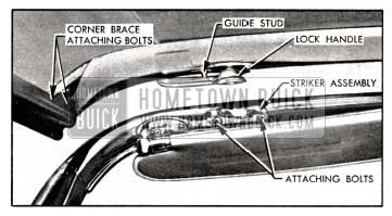
1958 Buick Front Roof Roil Corner Broce
Repeat on opposite side if necessary. NOTE: This adjustment is limited. If additional adjustment is required, it can be made at the 1958 Buick Convertible top male hinge.
Adjustment of Top at Lock Handle Striker and Front Roof Rail Guides
If a difficult locking action, caused by misalignment of the front roof rail lock handle strikers is encountered at the front roof rail, or if a closer fit of the front roof rail to the windshield header is desired, proceed as follows:
- Unlatch top and raise it above windshield header.
- Loosen striker attaching screws and adjust striker up or down or from side to side as required. If necessary, also loosen front roof rail guide attaching screws and adjust guide as required.
- If an additional upward adjustment of the front roof rail is desired, remove handle and install emergency washer into lock spindle cavity in handle, then install handle with emergency attaching screw.
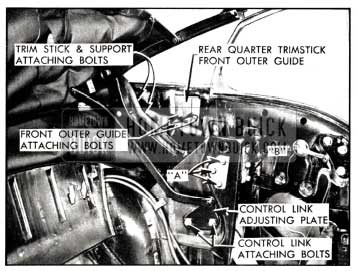
Adjustment of 1958 Buick Rear Quarter Trim Stick and Support Assembly
In some cases, the rear quarter trim stick and support assembly may be adjusted slightly to remove wrinkles of the top material at the rear quarter area. To adjust the trim stick and support proceed as follows:
- Remove screw securing 1958 Buick Convertible top compartment bag to end of rear seat back panel; then disengage compartment bag retaining clips from seat back panel as required to gain access to the trim stick and support assembly.
- Loosen support attaching bolts and outer guide attaching screws and adjust trim stick as required to obtain proper fit of top material; then tighten support attaching bolts.
- Lock front roof rail to windshield header; then position trim stick outer guide to contact top of inner guide and tighten outer guide attaching screws.
- Install compartment bag attaching screws.
Adjustment of Top at Control Link Adjusting Plate (All Series)
- If there is a sag in the joint between the front and center side roof rail, proceed as follows:
- Remove 1958 Buick Convertible top compartment side trim panel and operate top to the half-way up position.
- Loosen bolts securing control link adjusting plate indicated in Figures 13-96 or 13-97; then without any change in the fore or aft location of the plate, skip over serrations and position adjusting plate downward as required to eliminate the sag in the side roof rail.
1958 Buick Convertible Top Adjustments-Series 40-60
1958 Buick Convertible Top Adjustments-Series 50-70
- If the top linkage does not stack properly, proceed as follows: Operate top to the stacked position, then loosen the adjusting plate attaching bolts. Without any change in the vertical adjustment of the plate, position it forward or rearward as required to obtain the desired stack height.
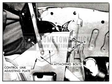
Adjustment of Top at Male Hinge Support (Series 40-60)
The male hinge is the same type of hinge that was used on the 1957 styles. The male hinge is secured to the support by three bolts at the front of the support and by three bolts at the side of the support. Prior to making an adjustment to raise the top linkage at the male hinge, loosen the two bolts securing the 1958 Buick Convertible top rear quarter trim stick front outer guide to the rear quarter panel. This will prevent any possible damage to the top when it is raised after adjustment. After making an adjustment at the male hinge, check the 1958 Buick Convertible top at the rear quarter area for proper fit and where necessary adjust the guide and the trim stick and support assembly.
- If there is an excessive opening between the side roof rail rear weatherstrip and the rear quarter window, or if the front roof rail is too far forward or rearward, proceed as follows:
- Loosen three male hinge attaching bolts “A” figure 13-96.
- Move hinge fore or aft, as required, then tighten bolts.
- Lock front roof rail to windshield header, and check side roof rail alignment and readjust if necessary.
- Lock front roof rail to windshield header and check fit of top material at rear quarter trim stick area and, if necessary, adjust trim stick. See “Adjustments of Rear Quarter Trim Stick and Support Assembly”. If adjustment is not necessary, tighten outer guide attaching screws.
- If the side roof rail is too high or too low at the rear quarter window area, proceed as follows:
- Loosen bolts securing rear quarter trim stick front outer guide.
- Loosen attaching bolt “B” figure 13-96. In addition to bolts, support is secured firmly in place by serrations on contacting surfaces of support and brace.
- Adjust support up or down as required, then tighten bolts.
- Lock front roof rail to windshield header, and check side roof rail alignment. Readjust if necessary.
- Check fit of top material at rear quarter trim stick area and, if necessary, adjust trim stick front guide. See “Adjustment of Rear Quarter Trim Stick and Support Assembly”.
Adjustment of Top at Male Hinge Support (Series 70-700)
The adjustments at the male hinge support are similar to those on previous styles. Prior to making an adjustment to raise the top linkage at the male hinge, loosen the two bolts securing the 1958 Buick Convertible top rear quarter trim front outer guide to the rear quarter panel. This will prevent any possible damage to the top when it is raised after adjustment. After making an adjustment at the male hinge, check the 1958 Buick Convertible top at the rear quarter area for proper fit and where necessary adjust the guide and the trim stick and support assembly.
- If there is an excessive opening between the side roof rail rear weatherstrip and the rear quarter window, or if the front roof rail is too far forward or rearward, proceed as follows:
- Loosen four male hinge attaching bolts “A”. See figure 13-97.
- Move hinge fore or aft, as required, then tighten bolts.
- Lock front roof rail to windshield header and check side roof rail alignment, and readjust, if necessary.
- Lock front roof rail to windshield header and check fit of top material at rear quarter trim stick area and if necessary, adjust trim stick. See “Adjustment of Rear Quarter Trim Stick and Support Assembly”. If adjustment is not necessary, tighten outer guide attaching screws.
- If the side roof rail is too high or too low at the rear quarter window area, proceed as follows:
- Loosen bolts securing rear quarter trim stick front outer guide.
- Loosen attaching bolts “B”. In addition to bolts, support is secured firmly in place by serrations on contacting surfaces of support and brace.
- Adjust support up or down as required, then tighten bolts.
- Lock front roof rail to windshield header and check side roof rail alignment and readjust if necessary.
- Check fit of top material at rear quarter trim stick area and, if necessary, adjust trim stick front guide. See “Adjustment of Rear Quarter Trim Stick and Support Assembly”. If adjustment is not necessary, tighten outer guide attaching screws.
13-20 1958 BUICK CONVERTIBLE TOP TRIM ASSEMBLY (ALL SERIES CONVERTIBLES)
The 1958 Buick convertible top trim on 1958 convertibles is attached in a manner similar to that used on past models. A new method of sealing the top is used on the 1958 convertibles. The 1958 Buick Convertible top center section to side section seams are now factory-sealed on all service replacement 1958 Buick Convertible top trim assemblies. In production, the seams are thoroughly sealed with a new “barrier-type” nitrile sealer, then covered with a sealing tape which color-matches the inner lining of the top material. When installing a service replacement top additional sealing operations must be performed. These sealing operations are included in the “Installation of 1958 Buick Convertible Top Trim Assembly” procedure. The material required for performing the sealing operations are 3M Super Weatherstrip Adhesive (or equivalent) for cementing vinyl surfaces and 3M Convertible Top Sealer for sealing the cloth inner lining of the material.
Removal of 1958 Buick ConvertibleTop Trim Assembly
- Place protective covers on all exposed panels which may be contacted during procedure.
- Remove following trim and hardware items:
- Rear seat cushion and back. (Caution: Disconnect rear seat speaker wire if present).
- 1958 Buick Convertible top compartment side trim (arm rests).
- Sid e roof rail rear weatherstrip; then loosen top flaps from rail.
- At the front of body, raise front roof rail, remove retainers and front weatherstrip and detach top material from front roof rail. See Figure 13-98.
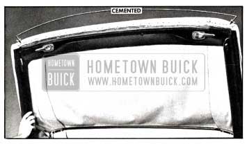
1958 Buick Trim Attachment at Front Roof Rail
- Detach 1958 Buick Convertible top compartment bag from rear seat back panel, thus exposing rear trim stick attaching bolts and rear quarter trim stick assemblies.
- At each rear quarter area remove two support attaching bolts and washers securing rear quarter trim stick and support assembly rear quarter inner panel. (See Figure 13-99.)
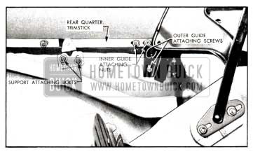
1958 Buick Rear Quarter Trim Stick and Support Assembly
- Remove rear trim stick attaching bolts; then lift trim assembly with attached quarter and rear trim sticks on top of rear compartment front panel. Remove nuts and washers securing front inner guide to rear quarter trim stick and remove inner guide.
- Remove screw securing escutcheon clip at each end of wire-on binding on rear bow. Then remove wire-on binding from rear bow and detach top material, side stay pads, back curtain and quarter stay pads from trim sticks and rear bow; then carefully lower rear bow. The trim sticks, with attached compartment bag, can be removed from body and placed on clean bench. See Figure 13-100.
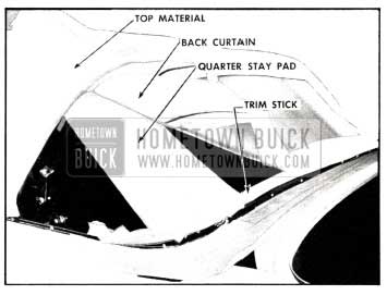
1958 Buick Convertible Top Component at Rear Window Area
- Loosen front end of side roof rail front weatherstrip sufficiently to detach top material flap which is cemented to rail.
- Remove side stay pads attached to front roof rail with tacks and to front and center bows with screws; then, lock front roof rail to windshield header.
Installation of 1958 Buick Convertible Top Trim Assembly
- Position rear bow for proper installation by installing spacer sticks as shown in Figure 13-101.
1958 Buick Rear Bow Positioning
Note that sticks are placed 30 inches apart, each being 15 inches from the centerline of body. The stick length “X” is approximately 18 1/2 inches for Buick “40” and “60” Series convertibles or 21 inches for Buick “70” and “700” Series convertibles, measured from chrome pinchweld molding to rear rolled edge of rear bow.
- As a bench operation, tack rear quarter stay pads to large trim stick, as shown in Figure 13-102.
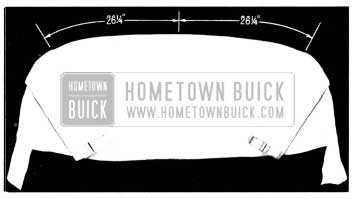
1958 Buick Tacking Rear Quarter Stay Pads
Note that inner edges of pads are 26 1/4 inches from center of trim stick. Lower edges of pads are set flush with lower edge of trim stick for positive location.
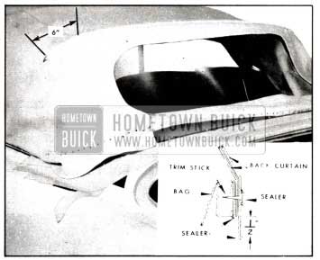
- Place back curtain window assembly on a clean covered work-bench with the exterior (vinyl) surface of the back window valance facing upward. (The large pliable back window must be handled carefully to avoid possible damage due to scratches, abrasions, etc.) Using a hand oiler apply a bead of 3M Convertible Top Sealer to both stitches which secure the back window to the zipper and the back window valance as indicated in Section “A-A” in Figure 13-103.
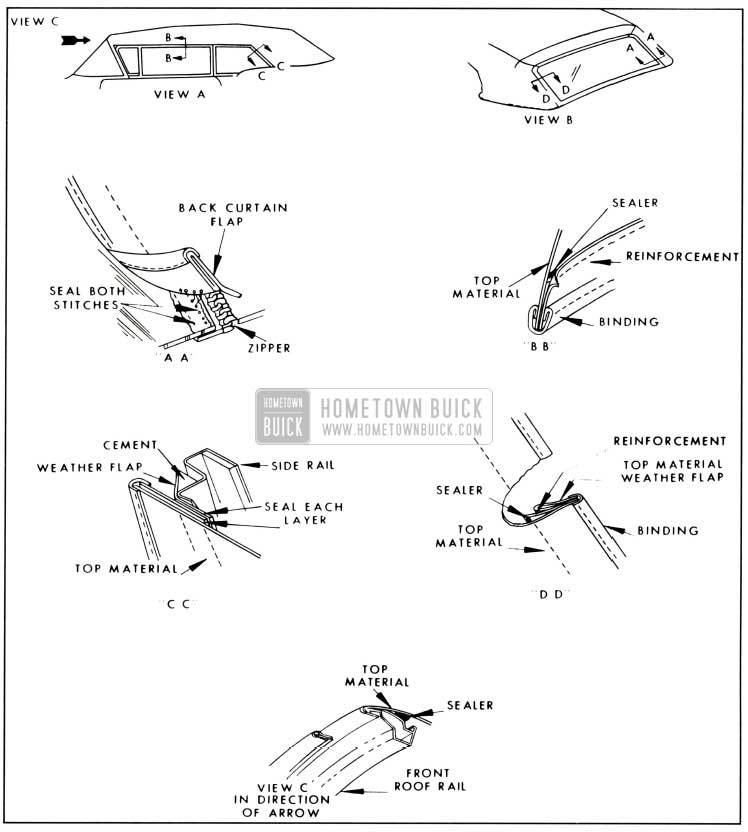
1958 Buick Convertible Top Sealing
- After sealer has dried, turn back window assembly over with the exterior (vinyl) surface of the back window valance facing down. Apply a bead of 3M Convertible Top Sealer along the inner lower edge of the back window lower curtain at the area which will be tacked to the rear trim stick. See inset in Figure 13-104.
1958 Buick Tacking Back Curtain
- Next, center and tack back curtain to rear trim stick as shown in Figure 13-105.
1958 Buick Back Curtain Assembly
The shorter lower edge of curtain should be set flush with lower edge of trim stick as shown in Figure 13-104. Tack curtain to a point opposite outer edges of window and leave outer ends of curtain loose. Tacks should be placed close to each side of every bolt hole in trim stick. Then pierce back curtain for each trim stick bolt.
- Inspect rubber trim stick fillers cemented to body below pinchweld as shown in Figure 13-106.
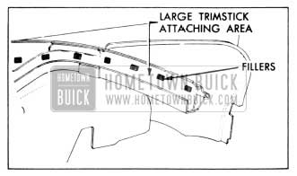
1958 Buick Trim Stick Fillers
Re-cement if necessary.
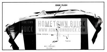
- Next, install rear trim stick, with pads and curtain attached, in body. Secure back curtain with one tack in rear bow to prevent damage to plastic sheet. See Figure 13-107.
1958 Buick Pad and Curtain Attachment to Large Bow
Attach the rear trim stick with bolts at each end, at the sharp bends and at center. Make sure that each bolt is driven completely in to represent finished conditions.
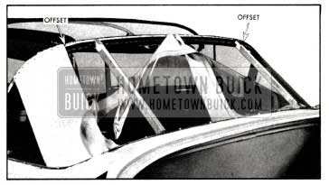
- Tack quarter stay pads to rear bow with inner edges located at the offset in rear bow as shown in Figure 13-107. Trim off excess material at rear bow.
- Install side stay pads in the conventional manner. Dimension “Y” in Figure 13-108 is approximately 17 3/8 inches for “40” and “60” Series convertibles or 18 inches for “50” and “70” Series convertibles and is measured from center of each bow at inner edge of the pad.
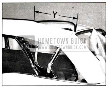
1958 Buick Positioning of Bows
- Remove spacer sticks when side pads have been installed.
- Tack back curtain to rear bow as shown in Figure 13-109.
1958 Buick Tacking Convertible Back Curtain
Make sure all fullness has been drawn from curtain before trimming off excess at rear bow.
NOTE: It may be necessary to install additional trim stick bolts to check the fit of the back curtain along belt line.
- Place replacement 1958 Buick Convertible top trim assembly on a clean work-bench with the inner lining (cloth) facing upward. Pull back side section reinforcement and with a hand oiler apply a bead of 3M Convertible Top Sealer along the stitches. An adequate amount of sealer should be used so that sealer can absorb into the cloth surfaces of the top material and the reinforcement material. See Section “B-B” in Figure 13-103.
- Apply a bead of 3M Convertible Top Sealer between the top material and the side section reinforcement in the rear quarter area and between each layer of the reinforcement as indicated in Section “C-C” in Figure 13-103.
- Apply a bead of 3M Convertible Top Sealer to the inner lining of the top material along the front roof rail. Sealer bead should be roughly parallel with the forward edge of the top material and located so that the sealer will be completely concealed by the front roof rail when top is installed. See View “C” in Figure 13-103.
- Pull back the top material weather flap reinforcement along both sides of the back window opening and apply a bead of 3M Convertible Top Sealer to the stitches as shown in Section “D-D” in Figure 13-103.
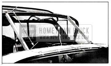
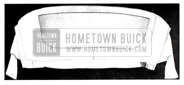
- Position top trim on frame work and center assembly both fore and aft and side to side. Positively locate top by engaging the weather flaps at back curtain as indicated in Figure 13-110. and by cementing the quarter flaps to side roof rails as shown in Section “C-C” in Figure 13-103.
- Stay-tack top to the rear bow; align and stay-tack the seams on outer ends of rear bow. See Figure 13-110.
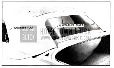
1958 Buick Installation of Weather Flaps and Quarter Flaps
- At front roof rail, pull top material forward (do not stretch excessively tight) and cement front flaps to the side roof rail. See Figure 13-111.
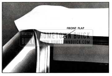
1958 Buick Cementing Front Flaps
- Remove trim stick bolts and install top material into body. Trim stick bolts beneath the back window must hold trim stick in position during following operation.
- Inside bod y draw down outer ends of back curtain and top material. When it has been determined that back curtain and top material are fitting- properly together and to the pinchweld finishing molding, mark curtain and top as shown in Figure 13-112 and install enough trim stick bolts to maintain position.
1958 Buick Positioning Back Curtain
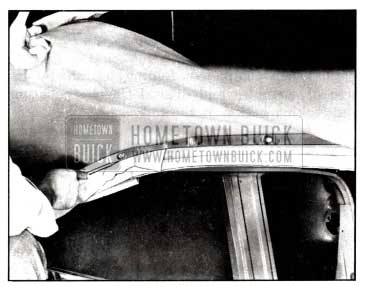
- At the front of body, draw top material forward across front roof rail which must be locked to windshield header. When most of fullness is removed, mark underside of top material along front edge of roof rail.
- Then, unlock roof rail and apply trim cement to lower side of rail and to top material which will contact this portion of rail. See Figure 13-98.
- Align and cement the top material to the front roof rail, lock top and check fit of top material. Make any necessary alterations to the position of the top material at this time.
- Next unlock the top and tack the material to rail. See Figure 13-98.
- Install front roof rail front weatherstrip and retainers and lock front roof rail.
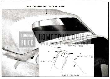
- Recheck final marked position of back curtain outer ends and top material at rear trim stick. Draw rearward section of the top material (back curtain upper valance) forward and upward to desired tension (not “drum” tight) and tack material to rear bow.
- Apply a continuous bead of 3M Super Weatherstrip Adhesive (or equivalent) to the tacked edge of the back curtain upper valance as indicated at “A” in the inset in Figure 13-119. Allow adhesive approximately 10 minutes to air-dry.
- Draw forward section of the top material rearward to desired tension (not “drum” tight) and tack material to rear bow as shown in Figure 13-119. Trim off excess material. NOTE: The tacks outboard of seams should be restricted to a distance not to exceed six inches, which is the length wire-on binding extends past seam as indicated in Figure 13-111.
- After the rear edge of the forward section of the top material (with the factory installed tape) has been tacked to the rear roof bow and the edges trimmed off, apply a bead of 3M Super Weatherstrip Adhesive (or equivalent) to the edge of the trim material, around each tack head, and into the two holes pierced into the top material for the wire-on binding clip escutcheons. See “B” in the inset in Figure 13-113.
1958 Buick Sealing at Rear Bow
NOTE: Adhesive should be confined as closely as possible to the trimmed edge of the top material so as not to be visible after installation of wire-on binding.
CAUTION: All painted surface s adjacent to the belt finishing molding should be adequately covered to prevent possible sealer damage.
- Detach rear trim stick and tack outer ends of back curtain and top material to stick as shown in inset in Figure 13-114.
1958 Buick Top Attachment at Rear Trim Stick
Use marked line as locating reference.
- Brush 3M Convertible Top Sealer onto all trimmed edges, around each tack head and around each trim stick attaching bolt hole. See inset in Figure 13-114.
- Install rear trim stick with all bolts, and install wire-on binding and clip escutcheons.
- Inside of bod y, draw quarter section of top material to desired position with short trim stick held in place by hand. Then mark top material in same manner as was done at rear trim stick. See Figure 13-112.
- Remove bolts at end of rear trim stick to loosen top material in rear quarter area. Then place small rea r quarter trim stick in position along previous marking, roll stick to expose tacking surf ace and tack top material to trim stick.
NOTE: Make certain front inner guide attaching holes are at forward end of trim stick.
- Cut holes in top material to conform to holes in quarter trim stick for front inner guide.
- Brush 3M Convertible Top Sealer onto all trimmed edges, a round each tackhead and around each trim stick front inner guide attaching bolt hole.
- Position front inner guide on outboard edge of rear quarter trim stick and secure in place by two nuts and washers. (See Figure 13-99).
- Insert end of inner guide into outer guide channel and install two bolts securing trim stick and support assembly to rear quarter inner panel. Install previously removed bolts from end of rear trim stick. (See Figure 13-99).
- Check alignment of top in quarter area and make any necessary adjustments.
- When completed, 1958 Buick Convertible top should be free of wrinkles and draws. Check operation and locking action of the top.
- Install all previously removed trim and hardware and clean any soilage from top material, back curtain or pads.
Removal and Installation of External Top Material Only
To install the external top material only, remove the material without disturbing the back curtain or stay pads. Then, reinstall the replacement top trim as outlined in the preceding installation procedure, beginning with step 12.
Removal and Installation of 1958 Buick Convertible Back Curtain Only
To install a replacement back curtain, it is necessary to detach the top material from the rear belt trim sticks and from the rear bow. By making reference marks on the 1958 Buick Convertible top trim along the belt molding, the top material may be returned to its original position with a minimum of refitting.
13-21 1958 BUICK HYDRO-LECTRIC SYSTEM (ALL SERIES CONVERTIBLES)
The convertible top Hydro-Lectric System is the same as used on past convertibles.
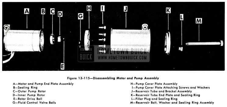
Figure 13-115 shows an exploded view of the motor and pump assembly. The parts are indicated by letters.
1958 Buick Disassembling Motor and Pump Assembly
Removal of 1958 Buick Convertible Motor and Pump Assembly
- Operate 1958 Buick Convertible top to full “up” position.
- Disconnect positive battery cable.
- Place protective covering over rear seat back and cushion.
- Working inside body, detach front edge of 1958 Buick Convertible top compartment bag from rear seat back panel.
- Working on inside of body over the rear seat back, remove pump and motor shield attaching screws and remove shield.
- Remove clips securing the wire harness.
- Disconnect motor leads from the wire harness, and remove clips securing hydraulic hose to rear seat back panel.
- To facilitate removal apply a rubber lubricant to pump attaching grommets; then carefully disengage grommets from floor pan. See figure 13-116.
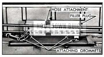
1958 Buick Motor and Pump Assembly Attachment
- Place absorbent rags below hose connections and end of reservoir.
- With a straight-bladed screw driver, vent reservoir by removing the filler plug; then reinstall plug.
NOTE: Venting reservoir is necessary in this “sealed-in” unit to equalize the air pressure in reservoir to that of atmosphere. This operation prevents possibility of hydraulic fluid being forced under pressure from disconnected lines and causing damage to trim or body finish.
- Disconnect hydraulic lines from sides of motor and pump assembly, and cap open fittings to prevent leakage of fluid. Use a cloth to absorb any leaking fluid, then remove unit from rear compartment.
Installation of Motor and Pump Assembly
- If a replacement unit is being installed, fill reservoir unit with specified Delco #11 hydraulic fluid (G. M. Hydraulic Brake Fluid Super #11). See “Checking Fluid in Reservoir” for proper fluid level.
- Connect hydraulic hoses, engage attaching grommets in panel and connect wiring.
- Remove reservoir filler plug and place absorbent rags under filler opening.
- Connect battery and operate top through its up and down cycle with filler plug removed from reservoir.
- Check connections for leaks and check fluid level in reservoir. See “Checking Fluid in Reservoir” for proper level.
- Install previously removed parts.
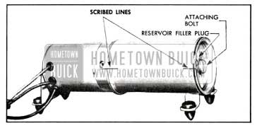
Disassembly of Reservoir Tube from Motor and Pump Assembly
- Remove motor and pump assembly from body.
- SCRIBE A LINE across the pump end plate, reservoir tube and reservoir tube end plate as shown in figure 13-117 to insure correct assembly of parts.
1958 Buick Motor and Pump Assembly
- With a straight-bladed screw driver, remove reservoir filler plug. Note sealing ring around plug.
- Drain fluid from reservoir into a clean container.
- With suitable tool remove bolt from end of assembly and remove reservoir end plate and tube. Note sealing rings around bolt, reservoir end plate, and between end of reservoir tube and pump assembly.
Assembly of Reservoir Tube to Motor and Pump Assembly
- Position sealing ring on pump and assemble reservoir tube to pump according to scribe marks.
NOTE: Bracket assembly on tube should be located at outer end when tube is assembled to pump.
- Position sealing ring on tube end plate and place end plate on reservoir tube, lining up the scribe marks. Install and tighten attaching bolt.
- Place unit in horizontal position and fill with fluid until level of fluid is even with bottom of filler plug hole.
- Make sure the sealing ring is on the filler plug, before installing filler plug.
Operation of the 1958 Buick Convertible Top
The principles of top operation are the same as on previous models. When the control switch knob is pushed forward, the battery feed wire is connected to the red motor lead and the motor and pump assembly operate to force the hydraulic fluid through the hoses to the lower ends of the double-acting cylinders. The fluid forces the piston rods in the cylinders upward, thus raising the top. The fluid in the top of the cylinders returns to the pump for recirculation to the bottom of the cylinders. When the control switch knob is pulled rearward, the feed wire is connected to the dark green motor lead and the motor and pump assembly operate in a reversed direction to force the hydraulic fluid through the hoses to the top of the cylinders. The fluid forces the piston rods in the cylinders downward, thus lowering the top. The fluid in the bottom of the cylinders returns to the pump for recirculation to the top of the cylinders.
Operation of 1958 Buick Pump Assembly
The rotor type pump assembly is designed to deliver a maximum pressure in the range of 240 psi to 280 psi. The operation of the pump assembly when raising the top is as follows:
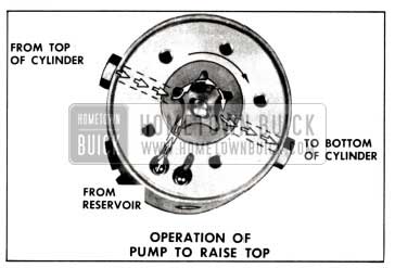
- Raising the Top. When the red motor lead is energized, the motor drive shaft turns the rotors clockwise as indicated by the large arrow in figure 13-118.
1958 Buick Pump Operation-Lowering Convertible Top
The action of the pump rotors forces the fluid under pressure to the bottom of each cylinder forcing the piston upward. This action causes the fluid above the piston in each cylinder to be forced into the pump, which recirculates the fluid to the bottom of the cylinders. The additional fluid required to fill the cylinder due to piston rod displacement is drawn from the reservoir as indicated.
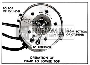
- Lowering the Top. When the green motor lead is energized the motor drive shaft turns the rotors counter-clockwise as indicated by the large arrow in figure 13-119.
1958 Buick Pump Operation-Raising Convertible Top
The action of the pump rotors forces the fluid under pressure to the top of each cylinder. This action causes the fluid below the piston in each cylinder to be forced into the pump which recirculates the fluid to the top of each cylinder. The surplus hydraulic fluid du e to piston rod displacement flows into the reservoir as shown.
Mechanical Checking Procedure
If there is a failure in the Hydro-Lectric system and the cause is not evident the mechanical operation of the top should first be checked. If the 1958 Buick Convertible top assembly appears to have a binding action disconnect the top lift cylinder piston rods from the top linkage and then manually raise and lower the top. The top should travel through its up and down cycle without any evidence of a binding action. If a binding action is noted when the top is being locked at the header, check the alignment of the door windows ventilators and rear quarter windows with relation to the side roof rail weatherstrips. Make all necessary adjustments for correct top alignment. If a failure continues to exist after a check for mechanical failure has been completed the Hydro-Lectric system should then be checked for electrical or hydraulic failures.
Electrical Checking Procedure
If a failure in the Hydro-Lectric system continues to exist after the mechanical operation has been checked the electrical system should then be checked. A failure in the electrical system may be caused by a low battery, breaks in the wiring, faulty connections, mechanical failure of an electrical component, or wires or components shorting to one another or to the body metal. Before beginning checking procedure, check battery according to procedure recommended in Buick Chassis Service Manual.
- Checking for Current at the 1958 Buick Convertible Top Control Switch
- Disengage connectors from the switch terminals.
- Connect light tester to yellow wire connector.
- Ground light tester ground lead to the body metal.
- If light tester does not light, there is an open or short circuit between the battery and switch.
- Checking the Folding Top Control Switch If there is current at the yellow feed wire connector, the operation of the switch can be checked as follows:
- Insert one end of a #12 jumper wire in yellow feed wire connector and the other end in the green or red wire connector. If the motor operates with the jumper wire but did not operate with the switch, the switch is defective.
- Connect jumper wire between center terminal (feed) and other motor wire terminal on switch terminal block. If motor operates with jumper wire, but did not operate with switch, the switch is defective.
- Checking Switch to Motor Lead Wires
If switch is found to be operating properly, the switch to motor lead wires can be checked as follows:
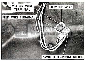
1958 Buick Checking Folding Top Control Switch
- Disconnect green switch-to-motor wire from motor lead in rear compartment.
- Connect a light tester to green switchto-motor wire terminal.
- Ground light tester ground lead to body metal.
- Pull switch control knob rearward. If tester does not light, there is an open or short circuit in wire.
- Disconnect red, switch-to-motor wire from motor lead.
- Connect light tester to red, switch-tomotor wire terminal.
- Push switch control knob forward. If tester does not light, there is an open or short circuit in wire.
Checking the 1958 Buick Convertible Motor Unit
If a light tester indicates current at the motor lead terminals of the switch to motor wires but the motor unit does not operate from the switch, a final check of the motor unit can be made as follows:
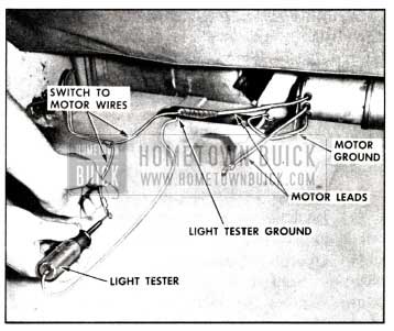
1958 Buick Checking Motor Lead Wires
- Check connection of motor ground wire to body metal.
- Connect a #12 gauge jumper from battery positive pole to motor lead terminal that connects to green switch-to-motor wire. The motor should operate to lower top.
- Connect jumper wire to motor lead terminal that connects to red, switch-to-motor wire. The motor should operate to raise top.
- If motor fails to operate on either or both of these checks, it should be repaired or replaced.
- If motor operates with jumper wire but will not operate from switch-to-motor wires, the trouble may be caused by reduced current resulting from damaged wiring or poor connections.
Hydraulic Checking Procedure
Failures in the hydraulic system can be caused by lack of hydraulic fluid, leaks in hydraulic system, obstructions or kinks in hydraulic hoses or faulty operation of a cylinder or pump. A pressure gauge can be used to check the pressure of the pump. See “Checking the Pressure of the Pump.”
- Checking Hydraulic Fluid Level in Reservoir
- Operate top to raised position.
- At the rear compartment, remove pump and motor shield.
- Place absorbent rags below reservoir at filler plug.
- With a straight-bladed screw driver, remove filler plug. Fluid level should be at the lower edge of filler plug hole.
- If fluid is low, add Delco #11 hydraulic fluid (G.M. Hydraulic Brake Fluid Super #11) to bring to specified level.
- Reinstall filler plug and pump and motor shield.
- Checking Operation of Lift Cylinders
- Remove rear seat cushion and 1958 Buick Convertible top compartment side panel assembly.
- Operate 1958 Buick Convertible top control switch and observe the lift cylinders during “up” and “down” cycles for these conditions:
- If movement of cylinder rods is not coordinated, or sluggish when the motor is actuated, check hydraulic hoses from motor and pump to cylinder for kinks.
- If one cylinder rod moves slower than the other, cylinder having slower moving rod is defective and should be replaced.
- If both cylinder rods move slowly or do not move at all, check the pressure of the pump. See “Checking the Pressure of the Pump.”
- Checking Pressure at the Pump
- Remove motor and pump assembly from rear compartment.
- Install plug in one port, and pressure gauge in port to be checked, as indicated in figure 13-122.
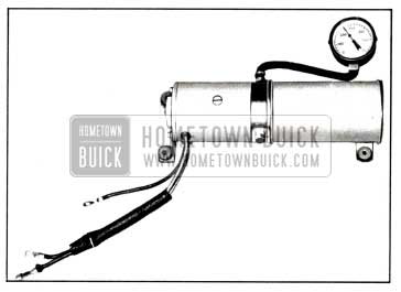
1958 Buick Checking Pump Pressure
- Actuate motor with an applied terminal voltage within range of 9.5 volts to 11.0 volts. Pressure gauge should show a pressure between 240 psi. and 280 psi.
- Check pressure in other port. NOTE: A difference in pressure readings may exist between the pressure port for top of cylinders and pressure port for bottom of cylinders. This condition is acceptable if both readings are within the limit of 240 psi. and 280 psi.
- If the pressure is not within specified limits, unit is defective and should be repaired or replaced, as required.
Removal of 1958 Buick Convertible Top Lift Cylinder
- Remove rear seat cushion and seat back.
- Remove 1958 Buick Convertible top compartment side trim panel.
- Remove attaching nut, bolt, bushing and washer from upper end of cylinder.
- Remove attaching screws from support at lower end of cylinder.
- Move cylinder to gain access to hydraulic hose connections.
- Disconnect and cap hydraulic connections on cylinder and on each hose.
CAUTION: Before disconnecting the hydraulic connections, place suitable wiping rags under the connections to absorb any drippage of hydraulic fluid. Also, disconnect the battery positive cable to prevent the accidental operation of the motor and pump while the hydraulic hoses are disconnected.
- Remove cotter pin, clevis pin, spacer and support from lower end of cylinder and remove cylinder.
- To install cylinder, reverse removal procedure with following exceptions: To aid in connection of cylinder piston rod to 1958 Buick Convertible top linkage use power to raise piston rod to extended position. Operate top down and up several times, then check and correct level of hydraulic fluid in reservoir.
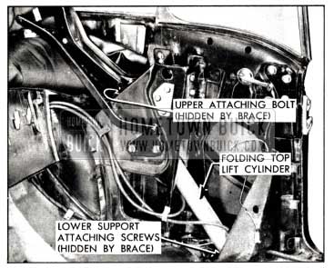
1958 Buick Convertible Top Lift Cylinder Installation-Series 40-60
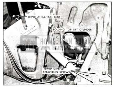
1958 Buick Convertible Top Lift Cylinder Installation-Series 70-700
Leave A Comment
You must be logged in to post a comment.