SECTION 13-D 1958 BUICK HEADLINING AND SEATS
13-12 1958 BUICK HEADLINING (ALL SERIES)
On the 1958 Buick “40” and “60” Series bodies the headlining is formed to the roof panel contour by concealed listing wires or by a combination of concealed listing wires and exposed roof bows. The 1958 Buick headlining is secured at the windshield and back window by cement and tacks, and along the side roof rail by tacks or a pronged retainer. In the rear quarter area the 1958 Buick head lining ma y be secured by cement or a pronged retainer. On the Buick “50” and “70” Series styles the 1958 Buick headlining is held in contour by concealed listing wires only. The 1958 Buick headlining is secured at the windshield and back window by tacks and cement and at the side roof rail by tacks. Following are headlining assembly removal and installation operations covering the use of concealed listing wires only, and the use of concealed listing wires and exposed roof bows. CAUTION: Clean hands are essential when working with headlining material.
Removal of 1958 Buick Headlining with Concealed Listing Wires
- Prior to removing headlining remove following trim and hardware assemblies:
- Rear view mirror and support
- Sunshade assemblies
- Windshield and back window garnish molding.
- Side roof rail finishing panels
- Coat hooks
- Place protective coverings over seat cushions and backs.
- Carefully remove all tacks or staples securing headlining at windshield, back window and side roof rails and detach cemented edges.
- Working from front to rear of body, detach headlining listing wires from side roof rails, gathering or rolling headlining and listing wires to keep headlining clean.
NOTE: At listing wire No.4 bend down tabs on center roof bow and detach listing wire from tabs. See figure 13-76.
1958 Buick Heading Attachment
- Remove 1958 Buick headlining from body and place on a clean bench. If necessary listing wires may be removed from headlining as a bench operation.
Installation of 1958 Buick Headlining with Concealed Listing Wires
- Install listing wires into 1958 Buick headlining listing pockets.
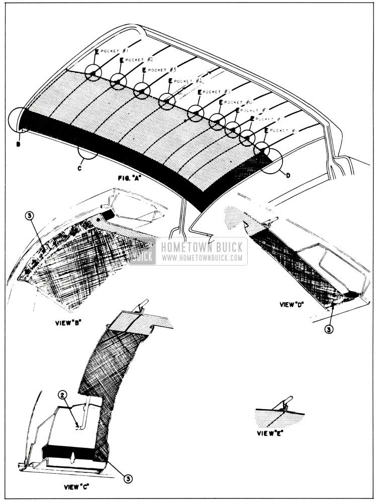
- Lift entire headlining assembly into body. Then starting at rear and working forward install listing wires No. 9, No. 8, No.7, No. 6 and No. 5 to side roof rails. (See figure 13-76.) To install listing wire tilt wire rearward, insert into roof rail holes as shown as “2” in View “C”; then swing wire to upright position and into locking notch in side roof rail. See figure 13-76.
- Install listing wire No. 4 in same manner as outlined in step No. 2. Align headlining; then secure listing wire to roof bow by bending tabs over listing wire. See figure 13-76. Install remaining listing wires.
- Center and align headlining in relation to windshield and back window openings, coat hook and sunshade locations. Then apply trim cement to headlining tacking surfaces at windshield and back window and stretch and stay tack headlining along side roof rails, and windshield and back window openings as shown at “3” in Views “C”, “B” and “D”. See figure 13-76.
- Remove all “fullness” and “draws” from headlining material and permanently tack headlining to tacking strips.
- Install all previously removed hardware and trim.
Removal of 1958 Buick Headlining with Concealed Listing Wires and Exposed Roof Bows
- Prior to removing 1958 Buick headlining remove following hardware and trim assemblies:
- Rear seat cushion and seat back.
- Rear view mirror and support.
- Sunshade assemblies.
- Windshield and back window garnish moldings.
- Side roof rail lamp assemblies or dome lamp assembly.
- Coat hooks.
- Side roof rail molding assemblies, where present.
- Carefully remove all tacks or staples securing headlining at windshield and back window openings and along side roof rails.
- At both right and left rear quarter trim panels, remove drive nails securing rear edge of panel and swing panel frontward to expose cemented end of headlining.
- Carefully detach cemented edges of headlining from back glass and windshield area.
- Loosen screws securing exposed roof bows to side roof rails.
- Working from front to rear of body, detach headlining listing wires and exposed bows from both right and left side roof rails, gathering or rolling headlining listing wires and bows to keep material clean.
- Remove 1958 Buick headlining from body and place on a clean bench. Listing wires and exposed bows may be removed from headlining material as a bench operation.
Installation of 1958 Buick Headlining with Concealed Listing Wires and Exposed Roof Bows
- Install listing wires in headlining pockets and exposed bows to cardboard foundation strips. Use extreme care when inserting cardboard foundation strips into grooves of exposed bows to prevent damage to headlining material.
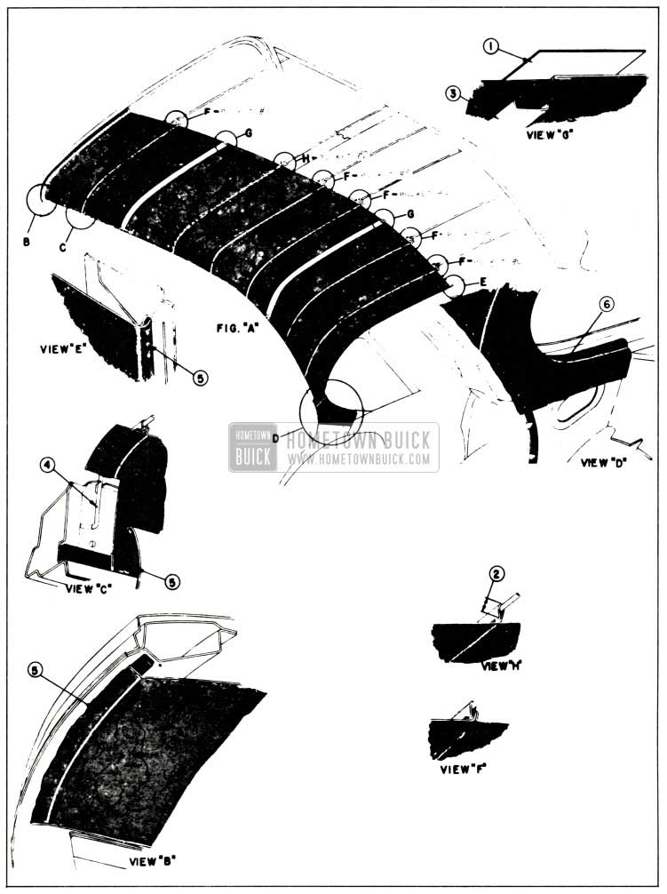
- Check to see that barrier strips as indicated at “1” in View “G” are securely cemented to deadener over areas where exposed bows will be located; and, if necessary, recement barrier strips using an approved trim cement. See figure 13-77.
1958 Buick Headlining Attachment
NOTE: Do not tighten roof bow attaching screws. To install listing wires, tilt wire rearward and insert into holes in side roof rail; then swing wire to upright position and into notch in side roof rail as shown at “4” in View “C”. See figure 13-77.
- Center and align headlining in relation to windshield, back window, side roof rails and dome lamp opening. Then cement and stay tack headlining material to tacking strips at back window, shown at “5” in View “E,” and windshield, shown at “5” in View “B”. Stay tack headlining along side roof rails as shown at “5” in View “C”. See figure 13-77.
- Working from front to rear, remove all “fullness” and “draws” from headlining material and permanently tack headlining to tacking strips.
NOTE: Make certain sunshade support openings in headlining are aligned with sunshade attaching screw holes.
- Adjust roof bows for proper tension on headlining to fill-out the material; then tighten bow attaching screws.
- Cement headlining at rear quarter as shown at “6” in View “D.” See figure 13-77.
- Install all previously removed hardware and trim parts.
13-13 1958 BUICK SEATS
Removal and Installation of 1958 Buick Front Seat Assembly Including Seat Adjusters (Series 40-60)
Operate seat midway between extreme forward and rearward positions. Remove 1958 Buick seat side panels.
- Loosen 1958 Buick sill plates, turn back floor carpet and remove two seat adjusters to floor pan bolts from rear of each adjuster.
- On styles with seat back lighter, disconnect lighter wire from feed wire and detach lighter wire from clip on floor pan.
- Aided by helper pull entire seat assembly rearward to disengage seat adjuster front legs from attaching brackets and remove seat assembly from body.
- To install, reverse removal procedure.
Removal and Installation of 1958 Buick Front Seat Adjuster (Series 40-60)
- Remove 1958 Buick seat assembly from body and place upside down on clean surface.
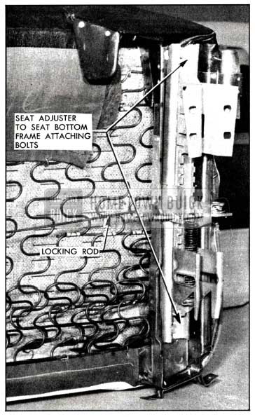
- Remove adjuster-to-seat bottom frame front and rear attaching bolts.
- With seat adjuster detached from seat bottom frame, the locking rod can be disengaged from seat adjuster.
NOTE: If a new locking rod is installed, remove the slack from rod and its attaching parts by using a suitable tool and crimping rod near right seat adjuster. See Fig. 13-78.
1958 Buick Locking Rod Installation
This operation is performed to insure a proper locking and unlocking action of right seat adjuster when operating control handle on left seat adjuster.
- To install, reverse removal procedure. NOTE: When attaching seat adjuster to seat bottom frame, be sure that right and left sliding mechanisms are in same relative position.
Adjustment for Additional Rearward Movement of 1958 Buick Front Seat (Series 40-60)
An additional 5/8 inch rea r ward travel of the front seat assembly can be obtained by bending tab in rear supports to clear lockbar support. To bend tab, remove lower seat side panel and with suitable tool bend tag to a vertical position. Perform same operation on the opposite adjuster.
Removal and Installation of 1958 Buick Front Seat Assembly Including Seat Adjuster and Motor and Regulator (All Horizontal Power Seats)
- Operate seat to extreme forward position. Remove seat side panels.
NOTE: When removing left seat side panel detach terminal block from switch before completely removing side panel.
- Under front of seat disconnect switch control wire harness from adjuster feed wire harness and detach control harness from slip on floor pan. On styles with seat back lighter, disconnect lighter wire from feed wire and detach from clip on floor pan.
- Loosen sill plates and turn back carpeting to expose rear seat adjuster-to-floor pan attaching bolts and remove bolts. With aid of helper pull entire seat assembly rearward to disengage front legs from brackets, and remove seat assembly from body.
- To install, reverse removal procedure.
Make certain ground wire is secured under seat adjuster floor pan bolt. Check operation of seat to extreme limits of horizontal positions.
IMPORTANT: When installing seat assembly in body, carefully align seat adjuster attaching holes with attaching holes in floor pan to prevent possible binding of seat adjuster linkage. Seat adjuster; should be parallel when properly aligned.
Removal and Installation of 1958 Buick Front Seat Adjuster Regulator and Motor (All Horizontal Power Seats)
- Remove 1958 Buick front seat assembly including seat adjusters and regulator assembly from body and place assembly up side down on a clean surface.
- Remove tensioner spring from right seat adjuster.
- Detach regulator motor wires from control harness.
- Using a screw driver, or other suitable tool pry open seat adjuster regulator rear support spring retainer sufficiently to disengage jack screw nut from support. See Figure 13-79.
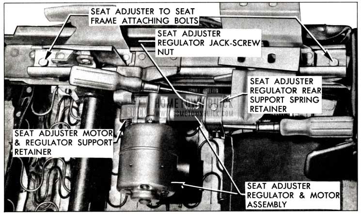
1958 Buick Horizontal Power Seat Regulator
Removal and Installation of 1958 Buick Seat Adjuster and Equalizing Rod (All Horizontal Power Seats)
- Remove seat assembly (including seat adjusters and regulator assembly) from body and place upside down on a clean surface.
- Remove tensioner spring from right seat adjuster and detach jack screw nut from support on left seat adjuster.
NOTE: If left seat adjuster is being removed, motor and regulator assembly must be removed.
- Remove seat adjuster-to-seat frame front and rear attaching bolts, Fig. 13-79.
- Lift adjuster slightly, then carefully work adjuster outboard to disengage adjuster from equalizing rod and remove from seat frame.
- To remove equalizing rod, remove rod support attaching bolts from side of seat frame from which adjuster has been removed; then disengage rod from support at opposite side of seat frame.
- To install, reverse removal procedure.
Removal and Installation of 1958 Buick Front Seat Assembly Including Seat Adjusters and Actuator (All Six-Way Power Seats)
- Operate seat to raised position and midway between forward and rearward horizontal position.
- Loosen sill plates and pull back carpeting to expose seat adjuster-to-floor pan attaching bolts.
- Under front of seat disconnect adjuster control wire harness from adjuster feed wire harness and detach control wire harness from clip on floor pan. On styles with seat back lighter disconnect lighter wire from feed wire connector and detach from clip on floor pan.
- Remove seat adjuster-to-floor pan rear attaching bolts; then with aid of helper pull seat assembly rearward to disengage front legs of adjuster from brackets and remove seat assembly including adjusters and actuator assembly from body.
- To install, reverse removal procedure. Make sure ground wire is secured under seat adjuster floor pan bolt.
IMPORTANT: When installing seat assembly to body, carefully align seat adjuster attaching holes with attaching holes in floor pan to prevent possible binding of seat adjuster linkages. Seat adjusters should be parallel when properly aligned.
After installation of seat assembly check all six operations of seat to extreme limit of each position.
Removal and Installation of 1958 Buick Front Seat Assembly Less Seat Adjusters and Regulator (All Six-Way Power Seats)
- Operate 1958 Buick seat to fully raised position and midway between full forward and rearward horizontal positions. Remove both right and left seat side panels and seat adjuster jack screw protector cover at front of seat.
- Under front of seat disconnect control wire harness from adjuster feed wire harness and detach control wire harness from clip on floor pan. Where present disconnect lighter wire from feed wire.
- At both adjusters remove front and rear seat adjuster-to-seat frame attaching bolts.
- Tilt seat assembly rearward and remove control wire harness from spring clips and retainer along front of seat bottom frame.
- With aid of helper carefully lift seat assembly (less seat adjusters and actuator assembly) from body.
- To install, reverse removal procedure. After installation of seat assembly check all six operations of seat to extreme limit of each position.
Removal and Installation of 1958 Buick Front Seat Adjuster-Right or Left (All Six-Way Power Seats)
- Remove 1958 Buick seat assembly (including seat adjusters and actuator assembly) from body and place upside down on a clean surface.
- Connect power to control harness feed wire and ground seat frame. Operate seat adjuster so that front of seat would be down, rear of seat up and seat in extreme forward position.
- Remove counter balance assist spring from both seat adjusters and tensioner assist spring from right seat adjuster, Fig. 13-80 and 13-81.
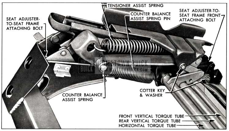
1958 Buick Front Seat Adjuster-Right
1958 Buick Front Seat Adjuster-Left
IMPORTANT: When installing seat assembly in body, carefully align seat assembly so that seat adjuster attaching holes are in line with attaching holes on floor pan to prevent possible binding of seat adjuster linkage. After installation of seat assembly, check all six operations of seat to extreme limit of each position.
Removal and Installation of 1958 Buick Seat Adjuster Torque Tubes (All Six-Way Power Seats)
One, two or all three torque tubes may be removed in the following manner:
- Remove right seat adjuster.
NOTE: Before removing adjuster make certain seat is positioned so that torque tube link to-spinning nut attaching screws, Fig. 13-81 are accessible for removal.
- At left end of torque tube being removed, remove cotter key and washer securing torque tube link to seat adjuster and two (2) screws securing torque tube links to spinning nuts.
- Carefully disengage torque tube linkage from left seat adjuster and from actuator assembly and remove from seat.
- To install torque tubes, reverse removal procedure.
IMPORTANT: When installing 1958 Buick seat assembly in body carefully align seat assembly so that seat adjuster attaching holes are in line with attaching holes in floor pan to prevent possible binding of seat adjuster linkage. After installation of seat assembly check all six operations of seat to extreme limit of each position.
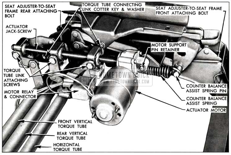
Removal and Installation of 1958 Buick Front Seat Adjuster Actuator (All Six-Way Power Seats)
- Remove front seat assembly (including seat adjusters and actuator assembly) from body and place upside down on a clean surface.
- Connect power to control harness feed wire and ground seat frame. Operate seat adjusters so that front of seat would be down, rear of seat up, and seat in full forward position. Remove counter balance assist spring from both seat adjusters and tensioner assist spring from right seat adjuster, Fig. 13-80.
NOTE: Spring can be removed with adjusters in any position; however, with adjusters positioned as described, springs are under the least tension.
- Operate seat adjuster so that all torque tube link-to-spinning nut attaching shoulder screws are accessible for removal; then disconnect ground wire and control harness feed wire from power source.
NOTE: Torque tube link attaching screws can be removed with adjusters in any position; however, with adjusters positioned as described, screws are easier to remove.
- Disconnect the three spinning nut solenoid feed wires at connectors and disconnect control harness wires from connector at motor relay. Fig. 13-82.
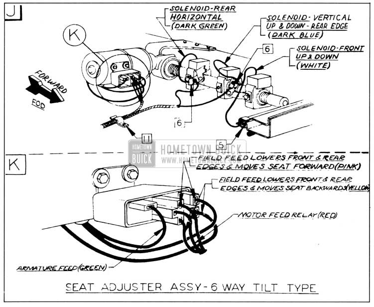
1958 Buick Seat Adjuster Assembly-6-Way Seat
NOTE: If installing new regulator assembly, transfers pinning nuts from old assembly to new assembly.
Removal and Installation of 1958 Buick Front Seat Adjuster Actuator Spinning Nut (All Six-Way Power Seats)
- Remove seat adjuster actuator assembly.
- As a bench operation carefully drive spinning nut stop pins, shown in Fig. 13-83, out of jack screw.
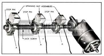
1958 Buick Six-Way Seat Actuator Assembly
IMPORTANT: When installing spinning nut stop pins, install pins so that center of protruding end of pin is located between threads of jack screw. Leave 1/16″ of pin protruding above jack screw threads, as indicated in Fig. 13-84.
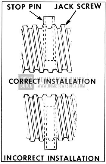
1958 Buick Spinning Nut Stop Pin Location
Removal and Installation of 1958 Buick Front Seat Back Robe Cord (Series 40-60)
- Remove robe cord escutcheon attaching screws from both sides of seat back. Remove both right and left seat back side panel attaching screws.
- Detach seat back side panel from seat back sufficiently to remove screw securing each end of robe cord and remove robe cord from seat back.
- To install front seat back robe cord, reverse removal procedure.
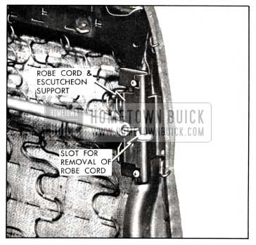
1958 Buick Robe Cord Attachment
Leave A Comment
You must be logged in to post a comment.