Project Description

1958 Buick Owners Guide
A 50 TH ANNIVERSARY MESSAGE from the PRESIDENT OF GENERAL MOTORS
1958 Buick Harlow Curtis
On the occasion of this our 50th Anniversary Year, it is a pleasure to welcome 1958 Buick Owners into the General Motors family of car owners. I wish I could welcome all 1958 Buick Owners personally and point out to them the many outstanding features that make this Golden Milestone car that is now theirs the very finest automobile that Buick has ever produced. However, 1958 Buick Owners have no doubt finding that out for themselves.
If you have owned a General Motors car before, may I thank you for your continuing patronage. It has helped make possible our progress, which in turn has contributed so much to the driving convenience, comfort and pleasure of so many millions of Americans.
If this is your first General Motors car, there is one important point I would like to impress upon you. In General Motors we recognize and to the best of our ability endeavor to observe this cardinal principle: that whatever success we have achieved or will achieve derives in whole from serving the customer well.
I am sure you will agree that our Golden Milestone lines of cars provide tangible evidence of this effort on our part to achieve full customer satisfaction. In quality and design they have built into them the accumulated experience and skill of our workers plus the technical advances which have come from the inquiring minds of our engineers, research men and other technicians.
A 50th Anniversary is important only as it serves as an occasion for taking stock and particularly for pausing to chart the road ahead. As we move into our second half-century, it is our firm resolve to make of it a second half-century of progress for our customers, for all those associated with us in the operation of our business and, to the extent that it lies within our power, for the country.
1958 BUICK OWNERS GUIDE
The 1958 Buick Owners Guide is compiled by the Buick Engineering and Service Deportment to assist 1958 Buick Owners in attaining the utmost pleasure and satisfaction from their car.
It is urged that 1958 Buick Owners follow the instructions and recommendations closely.
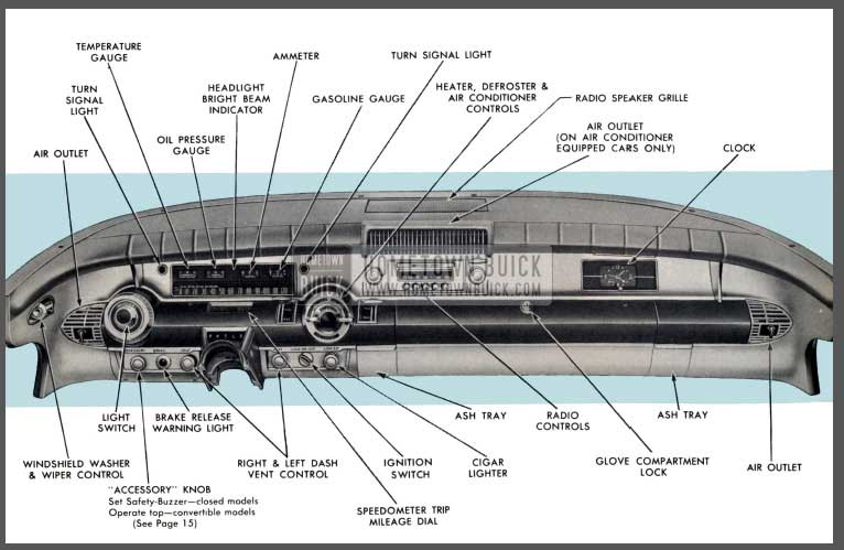
1958 Buick Instrument Panel
KEYS AND LOCKS
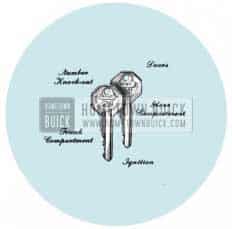
1958 Buick Keys and Locks
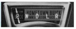
Identical keys operate all the locks on your Buick. Remove the “Knock-out” number and keep it in a safe place, to be used if your keys are lost or mislaid and duplicates are required. To lock the ignition, turn the key to “lock”; to shut off the ignition but still leave it operative with the key removed, turn the key to “off”.
A new feature has been incorporated in the ignition lock “off” position whereby the key cannot be removed until it is backed up slightly from the “off” position. This reminds the owner that the ignition is in the “off” (unlocked) instead of locked position when he removes the key. In the “off” (unlocked) position the switch may still be operated, yet the privacy of the glove and trunk compartments is retained.
Lock the ignition and the doors of your car when leaving it un attended. Over 75 % of the vehicles stolen have been left either with the key in the ignition lock or unlocked.
AUTOMATIC STARTING SYSTEM
When the engine is cold, depress the accelerator pedal just far enough to engage the starter. If the engine is warm, hot, or partially flooded, and does not start readily, depress the accelerator pedal to the floor and hold it there until the engine fires regularly. On both Variable and Flight-Pitch Dynaflow Drive cars, starter will not operate unless control lever is in “N” or “P”.
CAUTION: It is possible to damage certain parts of the radio if the starter is engaged while the radio is on. As an added precaution, do not attempt to start the engine unless the radio is off. The radio switch may be turned on after the engine is running.
ENGINE OIL
Selection – Engine crankcase oils have a definite effect on ease of starting, oil economy, combustion chamber deposits and engine wear. In selecting a specific brand of oil it is essential to consider the reputation of the refiner or marketer. See Page 54 for detailed information on selection of engine crankcase oils.
Maintaining Proper Oil Level – The oil gauge rod is marked with a “1 Qt.” line to indicate the amount of oil which must be added to maintain proper level. DO NOT OVERFILL. It is desirable that between changes the same brand of oil be used for additions. See Page 54 for detailed information on crankcase oils.
BREAK-IN PERIOD
The precision manufacture of your new Buick has eliminated the need for tedious low speed initial operation or break-in. However, the life of the engine, transmission and axles will be improved by the exercise of sensible care during this period. It is recommended that the speed not exceed 50 M.P.H. for the first 300 miles and that the rate of starting and stopping be moderate. After the first 300 miles 1958 Buick Owners may increase speeds above 50 M.P.H. gradually as mileage accumulates. During the first 1000 miles avoid driving for extended periods at any one speed, either slow or fast. Varying the speed of the car and including some higher speed operation, within the limits imposed by law, promotes longer life of parts and better economy of oil and gasoline.
Never subject your car to full throttle accelerations or high speeds until the engine has been thoroughly warmed up.
FUEL SELECTIONS
1958 Buick Fuel
As in your selection of motor oils, it is desirable to choose gasoline from a reputable refiner.
The 1958 Buick engine has been built to efficiently utilize the high octane characteristics of today’s fuels. The 40 series equipped with Synchromesh (Manual Shift) transmission is designed to use Regular fuel. All other Buick engines are designed to use high octane gasoline. Under normal city driving with partial country operation, the minimum octane requirements of Dynaflow equipped cars is 97 Research method, 87 Motor method at sea level. These octane requirements can be reduced 1 number for each 1000 feet of altitude, e.g. at 1000 feet elevation, the octane requirement will be 96 Research method and 86 Motor method, etc.
Some detonation or “spark rap” is not harmful; however, if it should become severe consult your Buick dealer as damage to motor engine parts could result. Since Buick considers engine failures resulting from use of low octane fuel as misuse of the engine, 1958 Buick Owners should always specify gasoline of the above octane rating when purchasing gasoline.
Do not become concerned if your Buick seems to be losing power under fairly high altitudes for any marked gain in altitude results in reduced air density and power.
If 1958 Buick Owners plan to operate their car in a foreign country where lower octane gasoline is sold, see a Buick dealer who will advise 1958 Buick Owners as to what engine mechanical changes are required for operation on such fuels.
Before leaving this country it is advisable to ascertain the octane ratings of fuels available in the country for which 1958 Buick Owners are destined. Such information may be obtained by writing to General Motors Overseas Operations, Service Dept., 9-164 General Motors Bldg., Detroit, Mich.
After arriving in a foreign country, contact the nearest Authorized General Motors dealer for brand names of the best fuels available and advice as to where they may be purchased.
LIGHTS
1958 Buick Light Switch
The 1958 Dual headlamp system provides 50 % higher wattage on upper beam and 25% on lower beam, thereby giving greater seeing distance on both beams.
When the upper beam (Bright ) is used, all four units are lighted. When the lower beam (Dims) are used, only the outboard units are lighted. For purposes of identification, the inboard units are marked “1” and the outboard units “2”.
Headlights, parking lights and instrument lights are controlled from a single three-way switch marked “LIGHTS” located at the left of the instrument panel. There are two “OUT” positions in the switch obtained by pulling the knob. The first position turns on the parking light and tail lights and the second position controls the headlights with the tail lights remaining on.
The lower and upper beams of the headlights are controlled for city and country driving by a foot-operated switch located on the car floor adjacent to the position of the left foot. When the upper beam is in use, a small red light is illuminated just above center of speedometer.
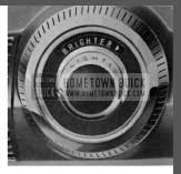
Instrument lights may be illuminated brightly in either position mentioned above by simply turning the knob to the extreme left (counterclockwise) position. Turning knob to right (clockwise ) diminishes the intensity of the instrument panel lights. Further rotation clockwise turns them off. All lights may be turned “off” by simply pushing the control knob all the way in. It is not necessary to turn the knob in either direction before pushing in the knob. When pulled out again, instrument lights will be illuminated as previously mentioned.
An ignition switch light is located just above and between the ignition switch and cigar lighter and is operated with the instrument lights.
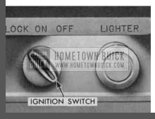
1958 Buick Ignition Switch
AUTRONIC-EYE
1958 Buick Autronic-Eye
The Autronic-Eye phototube, mounted on the instrument panel at the left of the windshield, picks up light from an approaching car’s headlights and automatically dims the headlights of your Buick. After the car has passed, the Autronic-Eye switches the headlights back to bright beam unless another oncoming car is within range of operation.
The foot operated dimmer switch mounted in the toe pan at the far left has two rachet positions plus a special “override” feature. The two regular positions are automatic and lower beam. The headlamps are con trolled by the Autronic-Eye in the automatic position only. In lower beam position, the headlamps are locked on lower beam.
The override section of the foot switch is ready to function only when the switch is in the automatic position. Lightly depressing the switch partway (over ride position) provides upper beam, regardless of the amount of light received by the phototube. This arrangement permits signaling oncoming car to dim lights and provides a simple test for automatic position of the foot switch.
CAUTION: This is on electronic device. All adjustments have been made at the Factory. The cover should not be removed nor any adjustment made except by an Authorized Buick Dealer. The windshield glass directly in front of the Autronic-Eye should be kept reasonably clean.
Operation in Automatic Position
- Turn on headlights and wait for a few moments to allow electrical components to become warm.
- Depress dimmer switch partway (about 1/4″); if high beams come on, Autronic-Eye is in automatic position.
- If high beam does not come on, fully depress dimmer switch to put eye in automatic position.
- Once eye is in automatic position, it is not necessary to use dimmer switch again. Eye can be left in automatic position at all times. It will keep lights in low beam position for city driving and will switch to high beam whenever it is dark enough for high beams to be necessary.
- To signal an oncoming car to dim its headlamps, depress the foot dimmer switch partway; then release. This momentarily flashes your headlights from lower beam (dim) to upper beam (bright).
- To keep headlights on upper beam (bright), depress the foot dimmer switch partway and hold in this position until 1958 Buick Owners desire the Autronic-Eye to automatically control the headlights.
- To keep the headlights on lower beam (dim), trip the foot dimmer switch by depressing it all the way.
NOTE: The loot dimmer switch must be fully depressed again to “automatic” position before Autronic-Eye regains control.
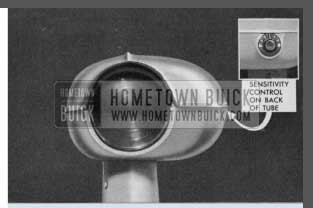
- If the driver desires to have lower beam come on when the approaching car is at a greater distance, turn sensitivity control dial clockwise. See Illustration. If lower beam is desired to come on at a closer distance, adjust control counter clockwise.
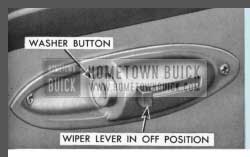
WINDSHIELD WIPERS
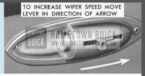
Vacuum-operated wipers are used for cleaning a large vision area on windshield glasses and are operated by pushing forward the sliding control lever located on lower left side of instrument panel extension. Speed of wiper operation is increased with forward movement of lever. On cars equipped with Cam-O-Matic wipers (standard equipment on Series 70 and 700 models, optional on all others) approximately the last half 01) inch of lever travel (forward) will give fast short stroke wiper action.
NOTE: It is recommended that wiper blades not be operated on dry gloss for prolonged period of time as it will shorten blade life.
WINDSHIELD WASHERS
1958 Buick Windshield Wipers
1958 Buick Windshield Washers
Washer is operated by firmly pressing the button on windshield wiper control panel. The washer will squirt for a short period automatically. On Buicks equipped with Cam-O-Matic wipers, the windshield wipers will come on automatically and will shut off when windshield is wiped dry. Keep the glass jar filled with water. In freezing weather use Buick windshield washer solvent part No. 980807 and do not fill over 3/4 full. Do not use water containing alcohol or other anti-freeze as it will damage car finish.
CIGAR LIGHTER

1958 Buick Cigar Lighter
The lighter is operated by pushing inward on the lighter knob. When the element is hot enough to light your cigarette, the lighter will return to its normal position. The ash-guard, a built-in feature on Buick lighters, may be pulled back toward the base to facilitate lighting cigars or pipes. The cigar lighter receptacle is illuminated when the instrument lights are turned on.
ASH TRAYS
1958 Buick Ashtrays
The two ash trays are blended into the instrument panel, one on each side of glove compartment door. To open an ashtray, simply place finger on top of rib and push down. Ash receiver may be readily removed for cleaning by lifting it out of the tray.
INSTRUMENTS
1958 Buick Instruments
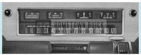
The speedometer, ammeter, gasoline gauge, temperature gauge, oil pressure gauge and speedometer trip mileage dial are all conveniently grouped in front of the driver.
The speedometer has an easy-to-read calibrated dial numbered from “0” to “120” (calibration appears only between “0” and speed indicated), with a trip mileage dial mounted directly underneath. The trip mileage reset knob mounted on lower flange of instrument panel, just to right of steering column, can be set at zero when starting on a trip. To reset, merely push in knob and turn in clockwise direction until all digits read zero. To adjust forward push in knob and turn counterclockwise direction. This resets reading forward by tenths of a mile.
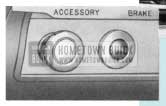
All Roadmasters and Limiteds are equipped with a Safety-Buzzer speedometer that sounds a warning when the maximum speed desired by the driver is attained. This Safety-Buzzer feature is a Factory installed option on all other series and may be adjusted to sound the buzzer at any speed between 20 and 110 mph by merely turning the knob marked “Accessory”.
A dial indicating the specific car speed at which buzzer will sound is located on lower left corner of speedometer face. Turn knob as required for desired setting.
NOTE: On convertibles the “Accessory” knob is used to operate the folding top; therefore, on these models a similar control knob is mounted on the instrument panel to the left of the “Accessory” knob for Safety-Buzzer setting.
When car is travelling at the speed for which Safety-Buzzer is set, the buzzer will sound and continue buzzing until either the speed of car is reduced below Safety-Buzzer setting, or speed 15 mph faster than Safety-Buzzer setting is attained. When Safety-Buzzer feature is not desired it may be set at “110”.

1958 Buick Safety-Buzzer
The ammeter, water temperature, oil pressure and gasoline gauges are of the conventional type having red pointer swinging in front of a black background.
NOTE: Under some conditions such as prolonged periods of engine idling or when driving in heavy slow moving traffic or when subjecting engine to heavy loads for long periods of time, the temperature gouge needle may be of H “hot”. Do not become alarmed for this con be considered normal provided radiator coolant is not lost due to boiling. If radiator boils see your dealer.
OUTSIDE AIR VENTILATION SYSTEM
1958 Buick Outside Air Ventilation System
This is a built-in ventilation system which is standard equipment on all Buicks, and is regulated by pulling either or both “Vent” control knobs as shown in Figure A. With these knobs pulled out, the forward motion of the car forces air through right and left ventilators mounted in the dash just above the floor mat.
Forced ventilation of outside air is readily available by setting “air control” lever as desired and operating blower.
NOTE: On Air Conditioner equipped Buicks, the right vent control knob is not to be pulled as it is a dummy knob used for decorative purposes only. The right dash ventilator is operated by tile Air Conditioner dial type lever control as explained later.
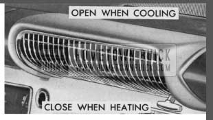
INSTRUMENT PANEL AIR OUTLETS
All Buicks equipped with heater and defroster have a non-adjustable air outlet mounted on each end of the instrument panel. See Figure B.
1958 Buick Instrument Panel Air Outlets
Air Conditioner equipped cars have adjust able air outlets at same locations. These outlets have a set of vanes mounted in a ring which may be rotated and tilted up or down like a venetian blind. By moving the control knob in or out and turning it, forced air may be deflected in any direction desired. See Figure C.
1958 Buick Instrument Panel Air Outlets Adjustment
During air conditioner operation, the air should be directed upward as far as possible to obtain maximum cooling performance.
During normal winter heater operation, the air should be directed down between the seat and door panels with front door ventilators, windows and dash ventilators closed. This setting gives even heat distribution to both front and rear seat passengers.
NOTE: The non-adjustable outlets have this setting.
HEATER AND DEFROSTER CONTROLS
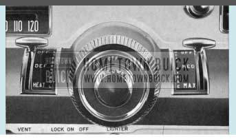
1958 Buick Heater and Defroster Controls
“Blower” switch has two (2) speeds, “HI” and “LO”. It controls the blower which draws in outside air for circulation through the heater and defroster outlets. In cold weather rotate knob to “HI” position to evenly distribute heat to front and rear compartments: Blower should be operated when driving slowly to provide good ventilation and reduce window fogging.
“Air Control” lever regulates the volume of air supplied by the blower to the windshield for defrosting and to the heater for heating. When defrosting is desired, place lever on “DEF” position. From this position further movement toward “HEAT” position gradually reduces the volume of defroster air and completely shuts it off when lever is placed on “HEAT” position at which time air is only directed to both instrument panel air outlets and outlet midway underneath instrument panel. When “Air Control” lever is placed midway between “DEF” and “HEAT”, air is equally directed to both defroster and heater outlets.
“Heat Range” lever is the temperature control which regulates the temperature of forced air provided by the blower. For coldest setting, place lever in “OFF” position. For warmest setting, move lever to “MAX” position. The lever may be set between “OFF” and “MAX” as desired to suit personal comfort. When “Heat Range” lever is in any position except “OFF” or “MAX”, temperature of car interior is automatically controlled.
An underseat heater is provided under the front seat to supplement the dash mounted unit and increase rear compartment temperatures. The temperature of both the dash mounted unit and underseat unit is controlled by the “HEAT RANGE” lever and blower as described above.
NOTE: Sudden changes in atmospheric conditions may cause interior sides of car windshield and windows to become fogged. Turn “Air Control” to “Defrost” and “Heat Range” to “Max”. In a matter of seconds glass areas will be clean and controls may be readjusted for personal comfort.
This condition is most likely to occur when car is driven on a rainy day with “Vent” valves open and the car enters a tunnel or in the winter when a quantity of snow might suddenly enter air system.
AIR CONDITIONER
Buick’s Air Conditioner system available as optional equipment consists of a mechanical refrigeration system which is combined with the heating and defrosting system to provide heating, defrosting, cooling, and dehumidification in any combination required by the weather.
AIR CONDITIONER CONTROLS
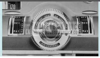
1958 Buick Air Conditioner Controls
“Blower” switch has two (2) speeds, “HI” and “LO”. It controls the blower which draws in outside air for circulation through the heater and defroster outlets and is also used for air conditioning. Rotate knob to position desired (“HI”, “OFF” or “LO”) as indicated.
NOTE: Air Conditioner Equipped Car-Blower cannot he turned off when Air Conditioner is “ON”. Blower operates at low speed in both the “OFF” and “LO” positions.
HEATER DEFROSTER OPERATION
The air conditioner controls have been combined with the heater and defroster for simplified operation, in that all three (3) units are operated by a dial type control mounted on the instrument panel, to the right of steering column. See Figure A. However, two separate temperature control levers are used with this arrangement; “cold range” control for air conditioner operation and “heat range” control for heater-defroster operation.
“Air Control Lever” regulates the volume of air supplied by the blower to the windshield for defrosting and to instrument panel air outlets for air conditioning or heating. When defrost ing is desired, rotate air control lever clockwise to “DEF” position. Further movement (clockwise) from this position gradually reduces the volume of defroster air and completely shuts it off when lever is placed on “Heat” position, at which time air is only directed to both instrument panel air outlets and outlet midway underneath instrument panel. When dial control is positioned midway between “DEF” and “HEAT”, air is equally directed to both defroster and heater outlets.
“Heat Range” lever is the temperature control which regulates the temperature of forced air provided by the blower. For coldest setting, place lever in “OFF” position. For warmest setting, move lever to “MAX” position. The lever may be set between “OFF” and “MAX” as desired to suit personal comfort. When “Heat Range” is in any position except “OFF” or “MAX” temperature of car interior is automatically controlled.
An underseat heater is provided under the front seat to supplement the dash mounted unit and increase rear compartment temperatures. The temperature of both the dash mounted unit and underseat unit is controlled by the “HEAT RANGE” lever and blower as described above.
AIR CONDITIONER OPERATION
“Air Control” rotating this lever clockwise to the “Air Conditioner On” position puts the compressor in operation and starts the air conditioner system when engine is running. NOTE: All windows and left vent must be closed. Movement of this lever through the “Air Conditioner” to “On” position closes the air outlet located midway underneath instrument panel and opens the right dash ventilator. During air conditioner operation the opened right dash vent permits return air from passenger compartment to be mixed with outside air. The mixture is then cooled before entering the passenger compartment.
“Cold Range” Lever
1958 Buick Air Conditioner Cold Range Lever
Moving this lever to “Max” position provides the greatest amount of cooling when blower is set for “Hi” operation. The lever may be placed any where between “Off” and “Max” position as desired to suit personal requirements.
An air outlet mounted on center of instrument panel is equipped with a valve which may be raised or lowered as desired for upper level cooling. During heater operation this valve should be closed completely.
In hot climates, when car is parked in the sun with the windows closed, it is recommended that the windows be opened for a short period of time to allow the accumulated heated air to be expelled. This will help your air conditioner to cool the car interior more quickly.
During rain, especially in mild climates when temperature is low and humidity is high, the air conditioner can be operated in conjunction with the heater by moving “Cold Range” lever to “Max” position and adjusting “Heat Range” lever to a location which will give desired car temperature. The air conditioner will dehumidify (dry ) air and the heater will then warm it.
It is recommended to operate the air conditioner for a few minutes periodically during the winter months or when air conditioner has not been in operation for long periods of time; doing so will lubricate the internal compressor seal and thus prevent possible loss of refrigerant. It is also recommended that the air conditioner be checked by your Buick dealer each spring in preparing for summer operation.
If the car is going to set in one position for any length of time with the air conditioner operating, selector lever must be in “P” range. This avoids an unnecessary load on the engine which may result in overheating under such conditions.
THE VARIABLE PITCH DYNAFLOW DRIVE
Control of the Variable Pitch Dynaflow Drive is obtained by positioning the control lever mounted directly below the steering wheel. Variable Pitch Dynaflow-equipped cars do not have a clutch pedal and lever may be placed in any position when engine is idling by merely moving the lever. Stops have been placed at certain points in the lever travel so that it is necessary to raise the lever to place it in certain positions. After a little experience driving the car, 1958 Buick Owners will find that it is possible to select a range merely by “feel” and visual reference to the dial will not be necessary. However, on all series the dial is illuminated for night driving and is controlled by the instrument panel lighting circuit.
When required, additional engine “braking” can be obtained by placing the lever in “L”.
NOTE: The starting motor circuit on cars equipped with the Dynaflow Drive is so wired that the engine will not start unless the control lever is in either “P” or “N” position.
THERE ARE FIVE POSITIONS INDICATED
1958 Buick Variable Pitch Dynaflow in P
“P” This is a Parking Lock and is to be used in conjunction with the foot operated “Step-on” parking brake. THIS PARKING LOCK MUST NEVER BE APPLIED WHEN CAR IS IN MOTION. Control lever must be raised to be placed in or out of this position. Parking the car with the control lever in “D”, “L”, or “R” positions will not partially brake the car as it does when 1958 Buick Owners leave a conventional transmission “in gear.”
1958 Buick Variable Pitch Dynaflow in N
“N” This is neutral and is to be used when towing the car and may be used instead of “P” when car is standing still and engine is running. Control lever must be raised when moving it from “D” to “N” position.
1958 Buick Variable Pitch Dynaflow in D
“D” This range is used for all normal forward driving. After the engine has been started, place Control Lever in “D” position and depress accelerator pedal. Nothing more need be done.
The new converter with Variable Pitch Stator Blades enables the driver to select the efficient cruising position or the greater performance position by the normal operation of the accelerator pedal. An added resistance to the accelerator pedal operation is provided near the end of its travel. By fully depressing the pedal through this point the higher performance setting is achieved.
1958 Buick Variable Pitch Dynaflow in L
“L” This range is to be used when the “going” is particularly tough, such as deep snow, or sand, or on long steep grades. To operate in this range, simply move the control lever to “L” position and drive as before. This range may also be used for “braking” the car speed on long or steep down grades.
Maximum acceleration from a standing start is obtained by starting in “L” and shifting to “D” at 35 M.P.H. The shift from “L” to “D” or vice versa may be made while the car is in forward motion by merely flipping the lever. These shifts should not be made at speeds over 40 M.P.H.
1958 Buick Variable Pitch Dynaflow in R
“R” This position reverses the car motion. To operate with car standing, raise and move control lever to stop at bottom of lever travel. Depress accelerator pedal for backing car.
PUSHING CAR TO START ENGINE
If it becomes necessary to push a Dynaflow Drive car to start the engine, place control shift lever in Neutral (N) until car speed reaches approximately 15 MPH, then shift into Low (L). Continue to increase car speed until engine cranks. After engine starts, return control lever to Neutral (N) for engine to warm up. It is safer to push car than tow it.
ECONOMY NOTE:
When driving Dynaflow cars, Buick owners have a choice of good performance with economy or superb performance. Good fuel economy may be obtained by making normal starts and not attempting to obtain maximum acceleration at all times. If, however, 1958 Buick Owners desire maximum performance on every start, 1958 Buick Owners must expect less fuel economy.
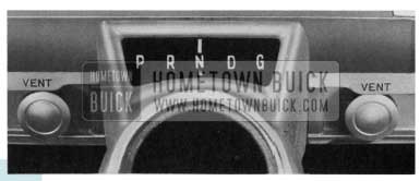
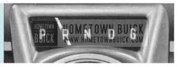
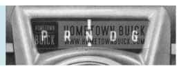
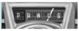
FLIGHT PITCH DVNAFLOW DRIVE
Control of the Flight Pitch Dynaflow Drive is obtained by positioning the control lever mounted directly below the steering wheel. A new selector quadrant is used on cars equipped with the Flight Pitch Dynaflow. The new sequence is P-R-N-D-G, with “G” representing the grade retard position. Flight Pitch Dynaflow-equipped cars do not have a clutch pedal and lever may be placed in any position when engine is idling by merely moving the lever. Stops have been placed at certain points in the lever travel so that it is necessary to raise the lever to place it in certain positions. After a little experience driving the car, 1958 Buick Owners will find that it is possible to select a range merely by “feel” and visual reference to the dial will not be necessary. However, on all series the dial is illuminated for night driving and is controlled by the instrument panel lighting circuit.
NOTE: The starting motor circuit on cars equipped with the Flight Pitch Dynaflow Drive is so wired that the engine will not start unless the control/ever is in either “P” or “N” position.
THERE ARE FIVE POSITIONS INDICATED
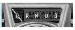
1958 Buick Flight Pitch Dynaflow in P
“P” This is a parking lock and is to be used in conjunction with the foot operated “Step-on” parking brake. THIS PARKING LOCK MUST NEVER BE APPLIED WHEN CAR IS IN MOTION. Control lever must be raised to be placed in or out of this position. Parking the car with the control lever in “R”, “D” or “G” positions will not partially brake the car as it does when 1958 Buick Owners leave a conventional transmission “in gear.”
1958 Buick Flight Pitch Dynaflow in R
“R” This position reverses the car motion. To operate with car standing, raise and move control lever to position indicated. Depress accelerator pedal for backing car.
1958 Buick Flight Pitch Dynaflow in N
“N” This is neutral and is to be used when towing the car and may be used instead of “P” when car is standing still and engine is running. Control lever must be raised when moving it from “N” to “R” position.
1958 Buick Flight Pitch Dynaflow in D
“D” This range is used for all normal forward driving. After the engine has been started, place control lever in “D” position and depress accelerator pedal. Nothing more need be done.
The new converter has a multi-pitch stator which affords an infinite number of blade positions between low and high angle, depending upon throttle opening. The blades are calibrated to automatically shift to the most efficient position. as the throttle opening increases to provide best overall economy and performance.
Fully depressing the accelerator pedal shifts the stator blades to the “High” angle position for maximum performance.
1958 Buick Flight Pitch Dynaflow in G
“G” Downhill grade braking, which in the Variable Pitch Dynaflow is achieved by the use of “Low” range, is achieved in the Flight Pitch Dynaflow by shifting to “Grade” (G) position. The design of the Flight Pitch Dynaflow in this range utilizes both the engine and the transmission converter as the braking forces. The “Grade” retarder clutch may be engaged at any vehicle speed below 45 mph to control car speed when descending grades.
CAUTION: Do not use this Range for pulling forward. Do not depress accelerator pedal when shifting from “D” to “G” range.
ECONOMY NOTE:
When driving Dynaflow cars, Buick owners have a choice of good performance with economy or superb performance. Good fuel economy may be obtained by making normal starts and not attempting to obtain maximum acceleration at all times. If, however, 1958 Buick Owners desire maximum performance on every start, 1958 Buick Owners must expect less fuel economy.
PUSHING CAR TO START ENGINE:
If it becomes necessary to push a Flight Pitch Dynaflow drive car to start the engine, place control shift lever in Neutral (N) until car speed reaches approximately 30 mph, then shift into Grade (G). Continue to push car until engine starts. After engine starts, return control lever to Neutral (N) for engine warm up. It is safer to push car than tow it.
BUICK AIR-POISE SUSPENSION
Buick’s Air-Poise Suspension is optionally available on all models equipped with power steering. This feature is one in which air cylinders replace the conventional coil springs to provide an even more comfortable and satisfactory ride.
In case of emergency when stuck in mud, snow, etc., chassis ground clearance may be increased by operating manual lift control to inflate cylinders and raise chassis. Approximately 5 inches additional ground clearance may be achieved if so desired. Never operate car with this increased ground clearance after emergency ceases.
Under unusual conditions such as frequent loading and unloading of passengers or other weight loads with engine not running, air in reservoir tank may be exhausted to the extent self leveling feature will no longer operate. Do not become alarmed for this is normal. Running the engine for a few minutes will restore car to normal level. Sometimes when engine is not running a slight hissing sound may be heard when weight load of car is changed. This also is normal for sound heard is that of air being exhausted when self leveling feature is in operation.
In the event a flat tire is experienced and the wheel and tire assembly is to be removed, it will first be necessary to pull the lift control knob all the way out. This knob is located underneath the instrument panel, to the right of center heater air outlet. NEVER ATTEMPT TO JACK CAR WITHOUT FIRST PERFORMING THE ABOVE. This automatically inflates air cylinders and raises the body to lock out the self-leveling feature. The bumper jack may then be used to raise the car and facilitate wheel removal. After wheel and tire assembly has been installed and jack removed, push in control knob; this will allow car to settle to its normal running height. NOTE: Alter control knob is pushed in, it will require a few minutes before car settles to normal position. Every 1000 miles, have your dealer drain water from air tank reservoir.
ADJUSTABLE FRONT SEAT
1958 Buick Adjustable Front Seat
The front seat on all Buick models is easily adjusted to any position forward or backward to provide maximum driving comfort. Manually-operated seats may be adjusted by merely pressing the control lever at the driver’s end of the seat and exerting slight body pressure either forward or backward. When in the desired position, the seat adjuster mechanism will automatically lock to prevent movement.
1958 Buick Six-Way Power Front Seat – Series 70-700
1958 Buick Six-Way Power Front Seat – Series 40-50-60
A six-way power seat is standard equipment on all 70 and 700 series and optional on all others except model 48. Three (3) separate double-acting switches mounted on the left door panel (in arm rest on 70 and 700 series) provide a means by which the seat may be adjusted in any one of six directions – forward, rearward, up, down, tilted forward or tilted rearward.
A forward or rearward movement is controlled by pushing the center button in direction of desired travel. The seat may be raised or lowered at either the front or rear, or both, by merely pushing the corresponding outer buttons (in or out). Tilting seat action may be acquired by raising the front end and lowering the rear or vice versa.
A six-way power seat for 40-50-60 models is controlled by three (3) double-acting switches mounted on the left side of front seat. Operation is basically the same as mentioned above except outer switch buttons are moved up and down.
Forward or rearward movement of two-way power operated seats, which is standard equipment on model 66C only, is controlled by pressing a button on driver’s end of seat in direction of desired travel.
STEP-ON PARKING BRAKE

1958 Buick Parking Brake
This is a mechanically operated brake which locks both rear wheels. This brake is operated with the foot and is located on the left side under the instrument panel.
This brake is self-locking and will remain applied until the “Brake Release,” located at lower left flange of instrument panel, is pulled up to release. This brake should always be released before the car is driven.
A red warning light on the instrument panel lights, if the ignition is turned on and the brake is not released. (Standard on Roadmaster and Limited. Optional on Series 40, 50 and 60.)
POWER BRAKES
Standard on Roadmaster and Limited. Optional on Series 40, 50 and 60 Dynaflow equipped cars.
Power brakes operate in the same manner as conventional Buick hydraulic brakes, except that about a third of the effort required to apply the brakes is furnished by the power cylinder.
In addition to the reduced effort required, the travel of the brake pedal is reduced by about one third.
The source of power to operate power brakes is furnished by the normal vacuum which is present in the intake manifold of the engine. A vacuum reservoir is provided in the pipe line from the power cylinder to the engine manifold. This tank insures instant response of the power cylinder when the brake pedal is depressed and also stores sufficient vacuum for 4 to 7 power stops after the engine stops.
After the supply of vacuum in the reservoir has been expended, the brakes will function unassisted by power but will require higher pressure of the foot on the pedal.
BUMPER JACK INSTRUCTIONS
To change front or rear tires:
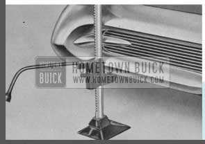
1958 Buick Changing Tires
- Set parking brake, remove hub cap and loosen wheel bolts.
CAUTION: If car is equipped with Buick Air-Poise Suspension, pull lift control all the way out to raise the body and lock out the self-leveling feature. This knob is located underneath instrument panel just to the right of center heater air outlet. Never attempt to jack car without first performing the above.
- When changing FRONT tires, place jack just outside bumper guard with lifting pad in hole provided in bumper rail. For REAR tires, place jack in notch provided in lower flange of bumper just inboard of tail light.
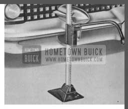
1958 Buick Bumper Jack
After tire is changed on car equipped with air-poise suspension and jack removed, push in lift control knob. This allows car to settle to its normal running height. NEVER OPERATE CAR WITH AIR CYLINDER FULLY INFLATED, UNLESS EMERGENCY EXISTS AS DESCRIBED ON PAGE 29.
CAUTION: Never work underneath car when it is supported only by the jack; always use additional safety stands to support the frame.
NOTE: Store jack between spore wheel and trunk side as shown before tightening wheel clamp nut.
HOOD OPERATION
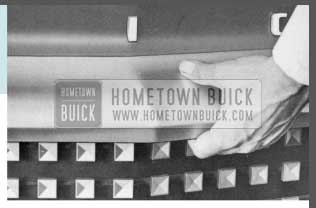
1958 Buick Hood Operation
The Buick hood is a conventional front-opening, spring counterbalanced hood of the so-called “alligator” type.
The hood latch is controlled from the front of the car by a pull rod between the radiator grille and the radiator grille header bar. To open the hood, locate the rod by placing the fingers under the header bar, slightly to the right of center. Pull for ward firmly and the hood-latch will release the hood. To lift the hood place fingers beneath the header and hood at the center and locate the safety latch. Pull forward as far as possible and then raise hood by lifting upward. The hinge design makes it advantageous to pull for ward as well as upward for easy raising of hood.
To close the hood, lower it to a near-closed position, then push firmly downward until the latch is fully engaged and the hood cannot be raised even slightly. If not properly locked, the hood will remain partly opened held only by the safety latch.
DIRECTION SIGNALS
To operate the turn signals, the ignition switch must first be turned on. The switch lever on the left of the steering column should then be pushed up for a right turn and down for a left turn. This action causes the front lamp and the stop light mounted at the extremity of the rear fender to flash on that side of the car in the direction the turn is to be made. If stop lights are applied at the same time a turn is indicated, the opposite stop light will remain solid.
Verification of the proper functioning of both front and rear lamps is indicated by the flashing of one of the illuminated green arrows, located on the ends of the speedometer.
If the arrow does not light and flash, after movement of the turn signal lever, it indicates that the signal system is not functioning properly and should be checked for burned out fuse, or bulbs in either front or rear signal lamps or the bulb which illuminates the green arrows.
Always indicate a turn at a reasonable distance before making the turn.
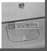
REAR COMPARTMENT
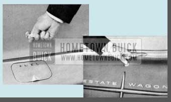
1958 Buick Trunk Handle
The compartment lid lock is located directly below the rear compartment ornament on all models except Estate Wagons. See illustration. Insert and turn key (clockwise) and raise the compartment lid, using lower edge of ornament as a handle. On Estate Wagon grasp handle and press button to open. To lock, firmly close lid.
BUICK RADIOS
Switch and Volume Control (Left Knob) The first portion of rotation in a clockwise direction turns on the radio. Further rotation increases volume.
Tone Control (Chrome Plated Knob Behind the Volume Control Knob) Control in extreme “treble” position gives brilliant tone reproduction. This position will reproduce speech very clearly and distinctly. Rotation counterclockwise (toward “bass”) diminishes brilliance and accentuates low notes. Full tone response is obtained with the control at center position.
REAR COMPARTMENT SPEAKER
A rear seat speaker is offered as optional equipment. This speaker can be used independently, or with the instrument panel speaker by turning the control knob located below the left air outlet to right or left depending on which speaker is desired on. Turning the knob diminishes the volume of one speaker and increases it on the other.
WONDER BAR SET-UP
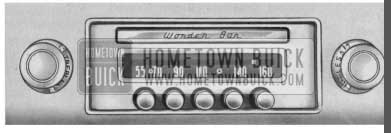
1958 Buick Wonderbar Radio
Buick’s Wonder Bar Radio incorporates all of the favorite tuning methods in one receiver, i.e. manual tuning, automatic “Wonder Bar” tuning and automatic foot switch tuning. When either the “Wonder Bar” or foot switch is depressed, the set automatically and quickly tunes in stations all along the dial which fall within the signal strength limits controlled by the “More-Less Station Knob.”
Signal strength limits may be set at any one of four positions by turning the sensitivity knob located behind the manual tuning knob to either “MORE” or “LESS.” Extreme movement of the knob toward “MORE” will include all available stations, provided the antenna is fully extended. By turning the knob to the extreme “LESS” position, nearly all stations are eliminated except strong local stations.
After setting the sensitivity control knob at any one of the four positions, turn on the set and move the dial indicator by either pressing the foot switch or the “Wonder Bar” on the front of the set. Touch either momentarily and the dial indicator will automatically move to the next station on the dial having sufficient signal strength to fall within the range for which the sensitivity control is set. By repeating this operation intermittently, the dial indicator will “search” the entire width of the dial and automatically return to the low frequency end of the dial ready to “search” the entire dial again.
The push buttons operate in the same manner as the Sonomatic Radio.
In some cases, when it is desirable to tune the set manually, simply operate the manual tuning knob at the right of the dial as with any conventional radio.
Tuning Control (Right Knob) When tuning manually, or when setting up a station on one of the buttons, remember-If the program sounds shrill or distorted, it is probably caused by improper tuning and can be corrected by adjusting the tuning knob slightly. Since the low notes are more affected by tuning than the high tones, it is a good plan to tune the set to a point where the low notes are heard best and the high notes are clear but not shrill.
IMPORTANT: In the event of a National Emergency when radio stations stop their schedule programs, be sure to tune in important Civil Defense information broadcast for you by the Conelrad Plan. With the manual tuning knob, set the radio dial pointed on one of the small Civil Defense triangles at 640 or 1240 kilocycles! This applies to both Wonder Bar” and “Sonomatic” radios.
SONOMATIC PUSH BUTTON SET-UP
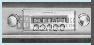
1958 Buick Sonomatic Radio
Setting the push buttons to tune to any desired station is a simple procedure requiring no tools or equipment.
Procedure Is as follows:
- Turn on radio.
- Press button to left and at the same time pull it out as far as possible.
- With this button out, tune in the desired station manually. (Do this very carefully as the push buttons will automatically repeat the tuning each time they are pushed. If incorrectly tuned when set up they will always be incorrect until setting is changed manually.)
- Push button in as far as possible. This automatically completes the button set-up and locks the mechanism in position.
(Both radios) – The Buick radio antenna is located on the left front fender opposite the windshield. The “manually-operated” antenna must be raised and lowered by hand.
The “electrically-operated” antenna (optional equipment on all models) may be raised or lowered from inside the car even while driving. A toggle switch mounted on the lower edge of the instrument panel to the left of the steering column raises the antenna when pulled toward the driver and lowers the antenna when pushed forward. For satisfactory radio operation, the antenna should be extended from half-way to the fully up position.
ELECTRIC CLOCK
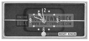
1958 Buick Electric Clock
Your new clock incorporates a sweep-second hand and an automatic regulator which regulates the clock toward fast or slow provided the reset knob is rotated in the direction the hands must move to correct the clock setting. If clock is running fast, turn the reset knob counterclockwise to correct the time. This resetting of hands will automatically make the clock run slower, likewise, if clock is running slow, turn the knob clockwise.
A lock out feature prevents the regulator from being moved more than twice during a 12 hour period, regardless of the number of times the clock has been reset. This permits the initial setting without affecting regulation.
IMPORTANT: If the clock is running FAST turn reset knob counterclockwise to reset. If clock is running SLOW turn reset knob clockwise to reset. This will automatically regulate clock a small amount.
NOTE: The electric clock requires special attention when reconnecting a battery that has been disconnected for any reason, a clock that has been disconnected, or when replacing a blown fuse. IT IS VERY IMPORTANT THAT THE INITIAL WIND BE FULLY MADE.
To be certain of this, proceed as follows:
- Make sure that all other instruments and lights are off.
- Connect one terminal of the battery first.
Before permanently connecting the other cable, touch the terminal to its post on the battery. Immediately afterward strike the terminal again to see if there is a spark. If there is, allow the clock to run down until it stops ticking and repeat as above until there is no spark. Then immediately make the permanent connection before the clock can again run down.
The above procedure should also be followed when reconnecting the clock after connections have been removed, or when replacing a blown fuse. Be sure to disconnect the battery cable before installing new fuse.
Failure of clock to run may be caused by any of the following:
Blown fuse-discharged battery-corroded battery terminals-wire improperly connected to fuse block or terminal connection to back of clock-or defective clock. In replacing fuse, use only 1-ampere AGA fuse on all Series.
REAR VIEW MIRROR
1958 Buick Rear View Mirror
Rear View Mirror is easily adjusted for correct visibility and to prevent headlight glare by simply adjusting the small ear on the bottom of the mirror in or out. The mirror can be adjusted to accommodate the driver’s height for greater driving convenience. Rotating the mirror 180° on its pivot will provide additional mirror height adjustment. NOTE: The mirror ball socket bracket is designed with an angle so that additional lowering adjustment may be achieved if desired. To accomplish this, merely remove mirror and invert it, then reinstall and rotate mirror as mentioned above to obtain desired setting.
NOTE: A three position rear view mirror is used on Roadmaster and Limited series only.
TIRES
Your Buick is equipped with tubeless tires mounted on disc wheels. These tires resist blow-out from impact breaks and give a slow loss of air instead of a blow-out. Puncture sealant is not specified in these tubeless tires; however, air loss due to a puncture is much slower from a tubeless tire and a nail can usually be left in until a service station can be reached. Tires should be inspected periodically, preferably each time the car receives Lubricare, and puncturing objects removed. When puncturing objects are removed, repairs will have to be made according to recommendations of the tire manufacturer.
For maximum tire service-keep tires properly inflated-use an accurate gauge-after inflating, be sure valve caps are in place and screw down fingertight.
EXTRA LOW PRESSURE TIRES
Use air pressure as indicated below for checking proper inflation.
1958 Buick Tire Over Inflation
1958 Buick Tire Under Inflation
1958 Buick Tire Proper Inflation
24lbs. (starting pressure) AFTER the car has been standing for three hours or driven less than a mile.
26 lbs. (city pressure) AFTER driving the car three miles or more BELOW 40 miles per hour.
28 lbs. (highway pressure) AFTER driving the car three miles or more ABOVE 40 miles per hour.
It is normal for air pressure to build up in a tire due to driving conditions. DO NOT LET AIR OUT OF TIRES TO REDUCE THIS INCREASE IN PRESSURE.
EQUALIZE WEAR ON TIRES
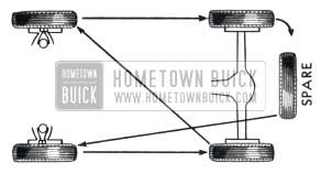
1958 Buick Tire Wear
CHANGE TIRES TO POSITIONS SHOWN IN DIAGRAM BELOW AT LEAST EVERY 4000 MILES.
This change of position helps out uneven wear on front tires and distributes the faster wear on the rear tires over all five tires.
CLEANING WHITE SIDEWALLS
Use mild soap, warm water, and stiff brush to remove road grime and curb dirt.
Use medium or fine steel wool for severe cases.
Do not use gasoline, kerosene, or any oil product that will discolor the sidewalls and rot the rubber.
By comparing air pressure in all tires, any variation in pressure will be evident. To prevent flat tires, investigate and correct a continued loss of air in any tire.
CONVERTIBLE COUPE
The power operating switch for raising or lowering top is the “Accessory” Knob located on instrument panel at left of steering column. See fig. 1.
1958 Buick Power Convertible Top Knob
TO LOWER TOP
- Stop car.
- Release locking handles above windshield.
- With ignition switch on, pull control knob away from panel and hold until top is approximately two (2) feet from completely lowered position.
- After top is lowered to this position, pull the top material and padding out from under the top operating arm. Actuate control knobs to completely lower top as shown in Fig. 2.
1958 Buick Convertible Top Cover
1958 Buick Raise Convertible Top
CAUTION: Before operating power top control knob marked “Accessory” make certain that the top directly above the windshield is raised slightly in order to clear windshield dowels.
TO RAISE TOP
- Stop car.
- Disengage top boot snap fasteners from molding; then turn boot over seat back and fold ends of boot toward center of car.
- Push control knob IN; hold knob IN until top is fully raised.
- Guide the studs on the front roof rail into holes in each lock striker; then engage each folding top locking handle with striker on windshield header.
To keep mechanism in good condition the top should be operated at least once a month. Do not operate top when temperature is below freezing (+32°F) or damage to top will result.
CAUTION: DO NOT OPERATE TOP EITHER UP OR DOWN WHILE CAR IS IN MOTION.
CARE OF CONVERTIBLE MODEL TOPS
The top should be washed frequently with neutral type soap suds and lukewarm water. A brush with soft bristles should be used. Generous quantities of clear water should be applied over the entire top to remove any trace of soap which might remain.
If the top requires additional cleaning after using soap and water, a mild bleach free foaming type cleanser can be used. A small hand brush having soft or nylon bristles should be used for scrubbing. Add water to the cleanser until a soapy consistency is attained and clean approximately two square feet of the top at one time. After scrubbing, remove the cleanser with a sponge. Care must be exercised to keep the cleanser from running down and across the body finish which may cause streaks. After the entire top has been cleaned, rinse the top generously with clear water to remove any trace of cleanser which might remain.
Volatile and other clear cleaners, naphtha, gasoline or household cleaners and bleaching agents should not be used.
NOTE: Buick Kar-Kleen and cleaner makes a very good cleaning solution.
CARE OF PLASTIC BACK WINDOW
To avoid scratches to which the back window is susceptible, use only a soft cotton cloth moistened with tepid ( not hot ) water and mild ( not caustic) soap. Rinse with clean water and dry with a slightly moistened soft, clean cloth. NO OTHER CLEANING METHOD IS RECOMMENDED.
POWER OPERATED WINDOWS
1958 Buick Power Windows
1958 Buick Right Power Window Switch
The master window control switch is located at the driver’s side in the upper roll of the instrument panel.
The right front door window control switch is located on the right side of the upper instrument panel roll.
The rear door and rear quarter window control switches are located on the trim panels at the window location.
BATTERY
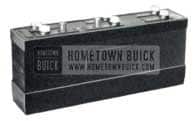
1958 Buick Battery
The Delco battery in your new Buick is warranted for 36 months under the terms defined in the Warranty Policy which has been placed in the glove compartment. Please read it carefully and retain it for future use if necessary.
Proper attention to your Delco battery will insure many months of satisfactory service. Periodically, it should receive the following attention:
- Add only distilled or demineralized water every 1000 miles or more frequently in warm weather. Do not over fill.
- Have battery checked regularly for state of charge. A lowcharged battery can freeze in extremely cold weather.
- Keep your battery clean. This prevents loss of charge and corrosion to hold-down bracket and cable connections.
Before doing any work around a battery a metallic contact between the car bumper and the ground should be made to remove the possibility of a static charge causing a spark in the vicinity of the battery. A long metal bar or a metal chain of sufficient length will accomplish this.
Your Buick dealer will gladly give you more information on the care of your battery but we also suggest that you read that portion of your Warranty Policy entitled, “Things You Should Know About Your Battery.”
CAUTION: Electric storage batteries give off a highly inflammable hydrogen gas when charging and continue to do so for some time after receiving a steady charge.
Under no condition should on electric spark or on open flame be allowed near the battery, particularly in the vicinity of the vent cops.
COOLING SYSTEM
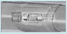
1958 Buick Radiator
The Buick cooling system is a sealed pressure type which raises the coolant boiling point.
As long as operating temperatures remain normal, there is no need to check coolant level when refueling, or stopping at Service Stations for other service.
Observe radiator cap removal precautions outlined below. Never add cold water when engine is overheated as the engine crankcase or cylinder heads may be damaged.
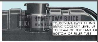
Recommended coolant level is at bottom of filler neck opening or at seam of top tank as shown in illustration. Do not overfill as loss of coolant due to expansion may result.
RADIATOR CAP
The radiator cap is the pressure type which opens to vent the cooling system only after internal pressure exceeds approximately 15 lbs. The pressure cap prevents loss of vapor by raising the boiling point of the coolant.
Pressure is maintained during normal operation due to the expansion of heated liquid. This pressure will be evident if cap is removed while system is hot. H the cap is removed, the pressure will be released and will result in coolant boiling. This is a normal condition and does not mean that the system is overheated. Therefore, should it become necessary to remove the radiator cap-use care. Turn cap to first stop to safely allow release of pressure. Only after pressure has been relieved should the cap be turned further and removed.
THERMOSTAT
The cooling system is controlled by a 160° F. thermostat which is installed in the water outlet housing, to maintain minimum satisfactory operating temperatures in cold weather.
NOTE: A 180° F. thermostat is available for use when maximum beater performance is desired in cold weather. Use only permanent type anti-Freeze with this thermostat.
ANTI-FREEZE
In cold weather, protect your cooling system with an anti-freeze solution to meet the maximum freezing condition expected where your Buick is operated.
Permanent-type anti-freeze such as Buick Non-Evaporating Anti-Freeze is especially recommended when driving conditions vary from extremely low to fairly high temperatures. Permanent-type solutions with ethylene glycol base do not evaporate and require only occasional checking.
Alcohol-type anti-freeze, due to evaporation, must be checked more frequently and if necessary, added to maintain proper protection. Before installing anti-freeze, the cooling system should be checked for leaks and all lose connections tightened.
Each year when preparing for cold weather operation install a fresh filling of anti-freeze. NOTE: Avoid mixing permanent type anti-freeze with alcohol type because it is difficult to accurately test such coolant mixtures with the type of testing equipment used at service stations.
CAUTION: When installing anti-freeze, do not use solutions that contain salt, oils, kerosene, glucose or honey. The cooling system has been treated at the factory with a special patented stop leak and inhibitor.
If, for any reason the system is ever completely drained, “Buick Radiator Stop Leak and Cooling System Conditioner”, Part No. 981441, should be added for maximum protection.
DRAIN
To completely drain the cooling system, open drain cock at bottom of radiator and remove pipe plug on each side of cylinder block. Loosen radiator cap when draining. The cooling system should be drained twice a year.
CARE OF CHROME AND DUCO FINISH
1958 Buick Chrome Finish
Calcium chloride and other salts, road tar, excretion from insects, tree sap, chemical from factory chimneys and other foreign matter may permanently damage the finish of cars.
Frequent, regular washing, thorough cleaning and waxing after exposure is recommended to prevent damage by these substances.
All exterior chrome plated parts should receive extra care during periods of ice and snow. At such times the use of salts or other chemicals as a snow removal aid, is very common. Such deposits should be washed off with water at very frequent intervals; as they are apt to be very destructive to chrome surfaces. As an extra precaution, the use of Buick Chrome Gard, part No. 981904 is recommended.
CARE OF ACRYLIC FINISH
On models that have an acrylic lacquer finish, the use of waxes or polishes is generally not recommended for 60 days after application of paint. NOTE: A sticker on the inside of the glove box door will indicate whether car has the acrylic finish. Treatments that may be used even during this 60-day period are Buick Beauty Glaze (dealer applied), Porcelainize (dealer applied), or Buick Hand Glaze, Part No. 981120, and Buick Hand Glaze Cleaner, Part No. 981121.
When removing road oils and tar from acrylic finishes, care must be exercised to use a cleaner that is not harmful to the finish. Ordinary tar removers that were developed for cleaning regular lacquer may be harmful. Instances have been reported where these commercial cleaners have caused spotting and in some cases extensive paint damage.
Any cleaner is satisfactory if it is recommended for use on acrylic lacquer. When purchasing, make sure that the instructions on the container specifically state that the contents can safely be used on acrylic and other finishes.
FREE WHEELING DOOR LOCKS
The rear door locks on four-door sedans are designed and are set so that the inside handles “free-wheel” when the locking button is pushed down into lock position. This prevents children from accidentally opening the rear doors. The feature can be changed by any Buick Dealer if it is not desired.
When lock is set for free-wheeling it is necessary to raise the lock button before either the inside or outside handles will open the door.
LAMP BULBS
1958 Buick Lamp Bulbs
FUSES
1958 Buick Fuses
*THERMAL RELAY – There are no fuses in the headlamp, tail lamp, parking lamp or instrument lamp circuits… Protection for these circuits is through a thermostatically controlled current limit relay attached to light switch. When the current load is too heavy, due to a short circuit, the relay opens and closes rapidly thus reducing current sufficiently to protect the wiring from damage. This action continues until the cause is eliminated.
SPECIFICATIONS AND DATA
1958 Buick Specifications and Data
GENERAL MAINTENANCE
ENGINE OIL
For instructions on maintaining proper oil level see Page 8.
The crankcase oil put in at the factory is a high quality Service M.S. oil (see below ) with special break-in additives so it should be left in for the first 1,000 miles.
Ordinarily, no further break-in oils or additives are needed. However, under some adverse driving conditions if such additives are necessary, your Buick dealer has available Buick Engineer-approved products for your use.
Oil should be normally changed after the first 1,000 miles (see Page 60 for filter service) and every 2,000 to 3,000 miles thereafter. Certain types of operation, however, such as short run, low speed operation in cold weather or in metropolitan areas where driving is limited to ten to twenty miles per day, or in extremely dusty territory, calls for more frequent changing. These oil change recommendations apply to multi-viscosity oils as well as to conventional viscosity oils. If there is any question about the change interval best suited for your type of driving, please consult your Buick dealer.
There are several types of oil manufactured for use in internal combustion engines. For use in the Buick engine we recommend that an oil, designated “For Service DG” or “For Service MS” (formerly called heavy duty type) be used for maximum protection under all driving conditions. “For Service ML” (formerly called regular type) and “For Service MM” (formerly called premium type) are not recommended for use in Buick engines.
Engine crankcase oils have a definite effect on ease of starting, oil economy, combustion chamber deposits and engine wear. Many commercial crankcase oils contain heavy non-volatile deposit forming components which make the type of combustion chamber deposits that greatly increase detonation and particularly pre-ignition, even though these oils may be designated “For Service MS” or “For Service DG.” Some commercial crankcase oils are deficient in anti wear characteristics and may contribute to rapid wear of camshafts, valve lifter assemblies and other highly stressed engine parts. Owners are urged to use only crankcase oils that have proven to produce ease of starting, satisfactory oil economy, minimizing combustion chamber deposits and produce adequate protection against wear.
The following chart will serve as a guide for the selection of the correct SAE viscosity number oil to use under specified atmospheric temperature ranges:
| TerritoryTemperature Spec. | SingleViscosity Oil | Multi- ViscosityOil |
| Not lower than +32°F. | SAE 20 or 20W | SAE 10W-30 or SAE 10W-20 |
| Not lower than -10°F. | SAE 10W | SAE 10W-30 or SAE 10W-20 |
| Below -10°F. | SAE 5W | SAE 5W-10W or SAE SW-20 |
EVERY 1000 MILES
Chassis – Wipe dirt from lubrication fittings, then apply a good grade of water-resistant chassis lubricant, under pressure, at the following points: (1) Upper and lower control arm inner pivot shafts, front and rear, (2) Steering Knuckle Ball Joints, (3) Tie Rods and Intermediate Rod, Steering linkage idler arm bushing, (4) Clutch Release Equalizer, (5) Clutch and throttle linkage may be lubricated (up to carburetor throttle rod only) with engine oil.
Synchromesh Transmission and Rear Axle – Check level at filler plug. Maintain level using SAE 90 Multi-Purpose Gear Lubricant (U.S. Army Spec. MIL-2105) for temperatures not lower than 10°F below zero. In temperatures continuously below -10°F, use SAE 80. Seasonal or periodic draining and flushing is not required. When complete refilling is required, however, use above lubricant in transmission but use only Factory Hypoid Lubricant in rear axle.
Dynaflow Drive – (Flight or Variable Pitch Transmission) – Check Transmission oil level, with transmission oil warm, transmission in Parking and engine idling. If level is more than one inch below “FULL” mark on gauge rod, add oil but do not fill above the “FULL” mark. Distance between “FULL” and “ADD OIL” marks on rod represents one pint. Use oil specified under “Every 25,000 Miles.”
Manual Steering Gear – Check level at filler plug. Maintain level using Multi-Purpose Gear Lubricant. Do not use pressure when filling. Seasonal or periodic change of lubricant is unnecessary.
Power Steering Gear – All models use a pump having an integral reservoir which supplies all necessary lubrication to the system, on Air-Poise suspension models this reservoir also supplies lubrication to the air compressor.
To check oil level, remove cover from reservoir and see if oil comes to specified level mark. Add oil specified for Dynaflow Drive to maintain level.
Distributor – Fill oil cup with SAE 10W engine oil.
Battery – Add distilled water to bring level to ledge at bottom of slot in well.
WARNING: Do not fill above ledge.
Air Cleaner – Normally serviced every 5000 miles. If car is operating in dusty territory, check condition of air cleaner and element and clean it if dirty. See cleaning instructions under “Every 5000 Miles.”
Rear Propeller Shaft – Remove pipe plug in torque tube for access to fitting. Apply chassis lubricant.
Radiator – Check coolant level only when radiator is cold. Maintain level at seam of tank. Filling above level line or when radiator is hot will cause loss of coolant.
CAUTION: Do not remove cop when radiator is hot because coolant will boil and overflow when pressure is released. When refilling cooling system alter draining, Temperature Control lever must be moved to Maximum position.
NOTE: If cooling system is being drained for storage where freezing is likely to occur, it is necessary to disconnect beater and defroster hoses to thoroughly drain them.
Manifold Valve Shaft – Place a few drops of graphited kerosene on shaft at each end and rotate shaft to work lubricant into bearings. If shaft is frozen, free up by tapping ends of shaft lightly with hammer.
Throttle Control Linkage – Place a few drops of engine oil at connections. Work Lubriplate into Equalizer Shaft bearings and wipe off surplus lubricant.
Generator – Fill front and rear oilers to the caps with light engine oil. Do not lubricate while generator is in operation.
Master Brake Cylinder – Thoroughly clean filler cap nut before removal to avoid getting dirt into reservoir. Add fluid as required to bring level to 1/2″ to 1″ below top of filler opening. Use G.M. or Delco Super No. 11 Hydraulic Brake Fluid. NEVER USE RECLAIMED FLUID OR ANY MINERAL OIL.
Air-Poise Suspension – Drain water from air tank reservoir.
CAUTION: After draining, dose drain code finger tight only. Do not use pliers or other tools.
Tires – Inflate all tires to pressures given on page 40.
WARNING: It is not possible to inflate tires correctly when they are bot.
Side Roof Rail Weatherstrip – On four-door Riviera Sedan and Riviera Estate Wagon, lubricate side roof rail weatherstrip with Silicone rubber lubricant such as Buick 4X Compound.
FIRST 1000 MILES
Lights – Check all lights and aiming of headlamps.
EVERY 5000 MILES
Air Cleaner – Every 5000 miles (more often under dusty operating conditions) disassemble air cleaner, remove and inspect element for proper sealing of the plastic ends. Clean element by tapping one of the plastic end plates gently and squarely on a clean flat surface. Extreme caution must be taken to prevent damage when tapping. Turn element over and repeat this process until the loose dirt has been removed. DO NOT WASH-DO NOT OIL-DO NOT CLEAN WITH AIR HOSE. Visually inspect element for possible breaks or holes in membrane which might cause dust leaks. Every 15,000 miles replace element with a new AC type A63C. (More often under dusty operating conditions.) Wipe interior metal surfaces clean prior to re-installation of element.
Crankcase Ventilator Filler Caps – Every 5000 miles or so, depending on driving conditions, clean and reoil, using the current viscosity engine oil.
Fuel Filter – Located in engine compartment. Remove glass bowl to clean.
Oil Filter – Change oil filter element at first 1000 miles, then 5000 miles and each 5000 miles thereafter.* Remove old element, and wipe container out thoroughly with CLEAN cloths. Install new element and new cover gasket. Use only Buick Oil Filter Replacement Element Part No. 5572128 (AC PF-122), or equivalent.
* In extremely dusty areas, more frequent change may be desirable.
Pump Operating Countershaft-Two Barrel Carter Carburetor Only – Remove the two dust cover attaching screws and apply several drops of engine oil in screw holes above counter shaft. Install screws.
Horn Cable Connector – Pull out plunger and apply a small amount of Lubriplate. Work plunger in and out.
Lights – Check all lights and aiming of headlamps.
Hood Fastener Mechanism – Lightly coat latch lever and pilot with Lubriplate.
Door Locks and Strikers – Apply G.M. Door-Ease Lubricant at the following points: (1) Top of bolt (2) Gear teeth on striker of each door.
Door Checks and Hinges – Apply Lubriplate or chassis lubricant to hold-open springs in front door hinges. Use same lubricant sparingly on lugs of all rear door check links. On check link pins of rear doors use Lubriplate. No lubricant required on hinge pins.
Estate Wagon – Use Lubriplate on tail gate support and hinges.
Dome Lamp Door Switches – Apply G.M. Door-Ease Lubricant to end of switch plunger and point of contact on door hinge pillar.
Glove Box Door – Apply a few drops of light engine oil to glove box door hinges-wipe off surplus oil. Sparingly coat lock striker with G.M. Door-Ease Lubricant.
Windshield Wiper Cables – Wipe Lubriplate on cables where they pass over tensioner pulleys.
CAUTION: Windshield wiper blades must not be rotated &y band for any reason as this places an undue strain on cable fastenings.
Rear Compartment Lid Lock – Lightly coat lock latch and lock striker with Lubriplate.
Lock Cylinders – If key operates roughly in lock cylinder, blow powdered graphite into key slot. DO NOT USE OIL.
EVERY 15,000 MILES
AIR CLEANER – Replace Element.
EVERY 25,000 MILES
Dynaflow Transmission (Flight and Variable Pitch) – At 25,000 mile intervals the oil pan and torque converter should be completely drained and re-filled with fresh oil. Transmission MUST NOT BE FLUSHED when oil is changed. Use Special Buick Oil for Dynaflow Drive or any Automatic Transmission Fluid, Type A, which has an AQ-ATF identification number embossed in lid of container.
Install 3 quarts of specified oil in transmission. Start engine. With engine idling and transmission in Park ( P) , complete the refilling by adding 9 additional quarts in a Variable Pitch Dynaflow or 9 1/2 additional quarts in a Flight Pitch Dynaflow.
To accurately check oil level of either Dynaflow, car must be driven (shifting transmission into all ranges) until transmission is at normal operating temperature; oil level should then be at “FULL” mark on gauge rod.
CAUTION: If oil level is checked without following these instructions, o false oil level may be indicated.
Air-Poise Suspension – Clean air filters in height and manual lift control valves.
AS REQUIRED
Front Wheel Bearings – Periodic re-packing of front wheel bearings is not required. Clean and re-pack if disassembled, using a good quality of water-repellent, high-temperature-resisting wheel bearing grease.
NOTE: Do not over fill bearings as excessive lubricant may be forced through seals and get on brake lining.
Rear Wheel Bearings – Rear wheel bearings need not be lubricated. Whenever axle shafts are removed it is advisable to inspect rear wheel bearings and oil seals. Replace seals if leaking or worn.
Bearing Adjustment – Take up spindle nut with 10″ wrench until bearings are preloaded at least 1 hex, then rotate wheel 1 revolution to make sure bearings are seated. Back off spindle nut until bearings are loose. Tighten nut until all bearing looseness is just removed, then tighten nut to nearest cotter hole and install cotter pin.
CAUTION: Bearing preload must not exceed 1/12 turn of nut.
Speedometer Cable – The speedometer cable is factory lubricated with special grease and normally requires- no further service unless it becomes noisy. In extremely hot climates, or where considerable dust and water is encountered it may be necessary to lubricate the cable at intervals of approximately 20,000 miles or every two years. It is advisable to have this service performed by an Authorized Buick Dealer to insure use of the special grease in proper quantity.
Sunshade – If sunshade rod turns hard in support, remove retainer screw, pull rod from support and apply G.M. Door-Ease Lubricant.
Do not use oil which may soil trim. Install rod in support and adjust retainer screw to proper tension.
Cleaning Leather – (1) Apply a damp (not wet) cloth to mild soap and rub surface of leather briskly. (2) Wipe with moist cloth without soap. (3) Rub dry with clean, soft cloth.
TRAILERS
Should 1958 Buick Owners contemplate hauling a house trailer with their Buick, it is advisable that 1958 Buick Owners follow our instructions covering weight limits, springs, tires, and hitch specifications. To obtain this information, write Buick Motor Division, Service Department, Flint, Mich.
ENGINE AND SERIAL NUMBERS
There are two identical numbers which identify your car. They are recorded by the License Bureau of the state in which your car is licensed.
SERIAL NUMBER – ALL SERIES
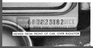
1958 Buick Serial Number Location
The serial number is located on a plate affixed to the left front pillar post below the belt molding line and is visible by opening the left front door.
ENGINE NUMBER
1958 Buick Engine Number Location
The engine number is located on top face of engine block extension, directly forward of the valve lifter cover.
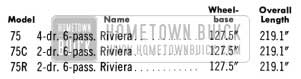
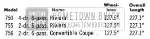
MODELS, WHEELBASES AND LENGTHS
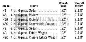
1958 Buick Special Series Wheelbase and Length
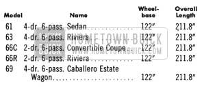
1958 Buick Century Series Wheelbase and Length
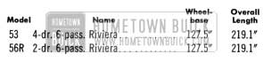
1958 Buick Super Series Wheelbase and Length
1958 Buick Roadmaster Series Wheelbase and Length
1958 Buick Roadmaster Limited Series Wheelbase and Length
Leave A Comment
You must be logged in to post a comment.