Project Description
1956 Buick Owners Guide
The 1956 Buick Owners Guide is compiled by the Buick Engineering and Service Departments to assist 1956 Buick Owners in obtaining the utmost pleasure and satisfaction from their car.
It is urged that 1956 Buick Owners follow the instructions and recommendations closely.
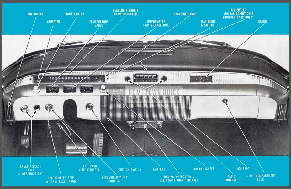
1956 Buick Instrument Panel
KEYS AND LOCKS
1956 Buick Keys and Locks
Identical keys operate all the locks on your Buick. Remove the “Knockout” number and keep it in a safe place, to be used if your keys are lost or mislaid and duplicates are required. To lock the ignition, turn the key to “lock”; to shut off the ignition but still leave it operative with the key removed, turn the key to “off.” The car may then be operated yet the privacy of the glove and trunk compartments retained.
Lock the ignition and the doors of your car when leaving it unattended. Over 75 % of the vehicles stolen have been left either with the key in t he ignition lock or unlocked.
AUTOMATIC STARTING SYSTEM
When the engine is cold, depress the accelerator pedal just far enough to engage the starter. If the engine is warm, hot, or partially flooded, and does not start readily, depress the accelerator pedal to the floor and hold it there until the engine Fires regularly. Always, in starting, be sure the shift lever is in “neutral.” On Dynaflow Drive cars, starter will not operate unless control lever is in “N” or “P”.
CAUTION: It is possible to damage certain parts of the radio if the starter is engaged while the radio is on. As an added precaution, do not attempt to start the engine unless the radio is off. The radio switch may be turned on after the engine is running.
ENGINE OIL
SELECTION
Engine crankcase oils have a definite effect on ease of starting, oil economy, combustion chamber deposits and engine wear. In selecting a specific brand of oil it is essential to consider the reputation of the refiner or marketer. See Page 30 for detailed information on selection of engine crankcase oils.
MAINTAINING PROPER OIL LEVEL
The oil gauge rod is marked with one quart and two quart lines to indicate the amount of oil which must be added to maintain proper level. DO NOT OVERFILL. It is desirable that between changes the same brand of oil be used for additions. See Page 30 for detailed information on crankcase oils.
BREAK-IN PERIOD
The precision manufacture of your new Buick has eliminated the need for tedious low speed initial operation or break-in. However, the life of the engine, transmission and axles will be improved by the exercise of sensible care during this period. It is recommended that the speed not exceed 50 M.P.H. for the first 300 miles and that the rate of starting and stopping be moderate. After the first 300 miles 1956 Buick Owners may increase speeds above 50 M.P.H. gradually as mileage accumulates. During the first 1000 miles avoid driving for ex tended periods at any one speed, either slow or fast. Varying the speed of the car and including some higher speed operation, within the limits imposed by la w, promotes longer life of parts and better economy of oil and gasoline.
Never subject your car to full throttle accelerations or high speeds until the engine has been thoroughly warmed up.
FUEL SELECTIONS
1956 Buick Fuel Selection
As in your selection of motor oils, it is desirable to choose gasoline from a reputable refiner.
The 1956 Buick engines have been built to efficiently utilize the high octane characteristics of today’s fuels. The 40 series equipped with synchromesh transmission is designed to use Regular fuel . All other Buick engines are designed to use high octane premium gasoline. Some detonation or “spark rap” is not harmful; however, if it should become objectionable, contact your Dealer.
LIGHTS
1956 Buick Lights
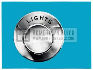
Headlights, parking lights and instrument lights are controlled from a single three-way switch marked “LIGHTS” located at the left of the instrument panel. There are two “out ” positions in the switch obtained by pulling the knob. The first step turns on the parking lights and tail lights, and the second step controls the headlights with the tail lights remaining on.
Instrument lights may be illuminated brightly in either step by simply turning the knob to the extreme left (counterclockwise) position. Turning the knob to the right (clockwise) diminishes the intensity of the instrument panel lights. The instrument panel lights may be turned off in either step by rotating the knob to the extreme right (clockwise) position. All lights may be turned “off ” by simply pushing the control knob all the way in. It is not necessary to turn the knob in either direction before pushing in the knob. When pulled out again, instrument lights will be illuminated as previously mentioned.
The lower and upper beams of the headlights are controlled for city and country driving by a foot-operated switch located on the car floor adjacent to the position of the left foot. When the upper beam is in use, a small red light is illuminated just above center of speedometer.
The map light is located just above the radio underneath top roll of the instrument panel and is turned on and off as the front doors are opened and closed. This light is also operated by the rear door on Super and Roadmaster models. A switch located to the left of the map light permits it to be turned on and off when doors are closed.

1956 Buick Map Light
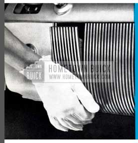
WINDSHIELD WIPERS
1956 Buick Windshield Wipers
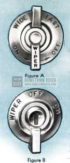
Vacuum-operated wipers are used for cleaning a large vision area on windshield glasses. A two-range, “Fast” and “Wide,” Cam-O-Matic wiper, standard equipment on Road master Series and optional on a11 other Series, is operated by turning the control knob located on lower edge of instrument panel at left of steering column Figure A. “Fast” operation may be used during heavy downpours or faster car operation when greater rain accumulation is encountered. “Wide” arc wiper operation is used to meet normal driving conditions.
Adjustable speed control (Special, Century and Super) is had by simply turning a knob which is also located on lower edge of instrument panel a t left of steering column. Figure B.
CIGAR LIGHTER
1956 Buick Cigar Lighter
The lighter is operated by pushing inward on the lighter knob. When the element is hot enough to light your cigarette, the lighter will return to its normal position. The ash-guard, a built-in feature on Buick lighters, may be pulled back toward the base to facilitate lighting cigars or pipes.
ASHTRAYS
1956 Buick Ashtrays
The two ashtrays are blended into the radio grille – one on each side. To open an ashtray, simply push on the lower part as shown. Ashtrays may be readily removed for cleaning by depressing the stop latch at rear of tray with thumb or finger.
INSTRUMENTS
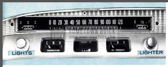
1956 Buick Instruments
The speedometer, ammeter, gasoline gauge, temperature gauge, oil pressure gauge, and speedometer trip mileage dial are all conveniently grouped in front of the driver.
The speedometer has an easy-to-read calibrated dial numbered from “0” to “120” with a trip mileage dial mounted directly underneath, between the temperature and oil pressure gauges. The trip mileage reset knob mounted below the windshield wiper control can be set at zero when starting on a trip. To reset, merely push in knob and turn in clockwise direction until all digits read zero. To adjust forward push in knob and turn counterclockwise direction. This resets reading forward by tenths of a mile.
The ammeter shows whether the battery is being charged or discharged and has a white pointer swinging in front of a green and red back ground. The pointer will be in the green area when t he generator is charging and in the red area when the battery is discharging.
The gasoline gauge operates in a manner similar to that of the charge indicator with the needle remaining in the green area until fuel supply drops below full at which time the needle will be in the red area, indicating low fuel supply.
The temperature gauge functions in a manner similar to that of the ammeter and gasoline gauge; however, a white pointer is mounted across an opening in a disc which also s wings in front of a green and red background. Green will normally be observed through the disc opening until abnormally high engine operating temperatures are approached at which time the gauge will show red.
The oil pressure gauge is similar to that of the temperature gauge. Under normal driving conditions this gauge will show green. When low oil pressure is encountered, the gauge will show red.
NOTE : When engine is idling, oil gauge may s how red; however, this can be considered normal if pressure picks up as engine RPM is increased.
WINDSHIELD WASHERS
Washer is operated by firmly pressing the small but ton in the center of the windshield wiper knob. The washer will squirt for a short period automatically; also, the windshield wipers will come on automatically and will shut off when windshield is wiped dry.
Keep the glass jar Filled with water. In Freezing weather use Buick windshield washer solvent part No. 980807 and do not Fill over Full. Do not use water containing alcohol or other anti-Freeze as it will damage car Finish.
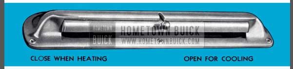
OUTSIDE AIR VENTILATION SYSTEM
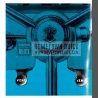
1956 Buick Outside Air Ventilation System
This is a built-in ventilation system which is standard equipment on all Buicks, and is regulated by pulling either or both “Vent” control knobs shown in Figure A. With these knobs pulled out, the forward motion of the car forces air through right and left ventilators mounted in the dash jus t above the floor mat.
NOTE: On Air Conditioner equipped Buicks, the right vent control knob is omitted; on these models the right vent is operated by a lever on the air conditioner control panel as explained later.
INSTRUMENT PANEL AIR OUTLETS
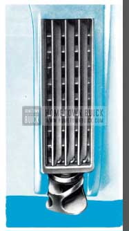
1956 Buick Instrument Panel Air Outlets
All Buicks equipped with Heater and Defroster or Air Conditioner have an air outlet mounted on each end of the instrument panel. Each outlet has t w o sets of vanes which may be adjusted vertically and horizontally by a knob so that forced air may be directed as desired. Figure B. To lower t he air stream, pull the knob down ward; to raise the air stream, raise the knob upward; and to deflect the air horizon tally, rotate the knob in the direction desired.
During normal winter heater operation, the air should be directed down between the seat and door panel with window s and dash ventilators closed. This setting gives even heat distribution to both front and rear seat passengers.
Forced ventilation of outside air is readily available through these outlets by merely operating the blower.
HEATER AND DEFROSTER CONTROLS
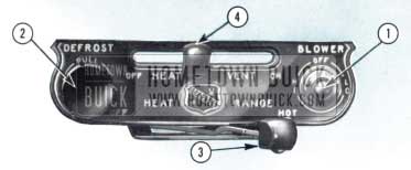
1956 Buick Heater and Defroster Controls
- “Blower” switch has two (2) speeds, “HI” and ”LO.” It controls the blower which draws in outside air for circulation through the heater and defroster outlets. Place switch in center position to turn blower off.
- “Defrost” knob, when pulled out, directs the flow of air supplied by the blower to the windshield. In cases of extreme side window fogging, adjust instrument panel air outlets so that air is directed up toward the side windows. For maximum windshield defrosting, place “Heat Range” lever in “HOT” position and “Heat and Vent” lever in “OFF” position, then pull out defroster knob; place blower on “HI”.
For less defrosting and more heating, push “Defrost” knob in, then move “Heat and Vent” lever to the right. Air may be directed equally to defroster and heater outlets by placing “Heat and Vent” control in center position and pulling “Defrost” knob out.
CAUTION: Due to the design of these controls, full defrost cannot be obtained at the same time as lull beat. Do not force controls as damage may result.
- “Heat Range” lever. is the temperature control which regulates the temperature of forced air provided by the blower. For coldest setting, place lever in “OFF” position. For warmest setting, move lever to extreme right position. The lever may be set between “OFF” and “HOT” as desired to suit personal comfort. When this lever is in any position except “OFF” or “HOT,” temperature of car interior is automatically controlled.
- “Heat and Vent” lever regulates the volume of heated or unheated forced air, depending upon position of “Heat Range” lever, supplied at three (3) outlets; one midway underneath the instrument panel and one at each end of instrument panel. The volume of air supplied to the passenger compartment at these points increases as the lever is moved from the “OFF” toward the “ON” position. For maximum rear compartment heating, make certain that all windows and outside ventilators are completely closed; then move this lever to “ON position and place blower on “HI. ” Refer to “Defrost” paragraph when defrosting is desired with heating.
AIR CONDITIONER
Buick’s Air Conditioner system available as optional equipment consists of a mechanical refrigeration system which is combined with the heating and defrosting system to provide heating, defrosting, cooling, and dehumidification in any combination required by the weather. In addition to these features, all outside air Flowing through the system is filtered.
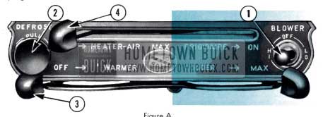
AIR CONDITIONER CONTROLS
The air conditioner controls have been combined with heater controls for simplified operation. See Figure A, Page 10.
The left half of the air conditioner control panel is used to operate the heater and defroster and is identical in operation to that of the “Heater and Defroster” described above; likewise, the “Blower” switches are identical.
- “Blower” switch is operated in the manner described above for “Heater and Defroster” and is also used for air conditioning.
- “Defrost” knob is also operated in the manner described above for “Heater and Defroster. ” Due to mechanical design, defroster cannot be opened when air conditioner is “On;” this prevents windshield fogging. NOTE: “Heater-Air Max” lever corresponds to “Heat and Vent” lever referred to in “Defrost” paragraph on page 9
1956 Buick Air Conditioner Controls
When this lever is in any position except “OFF” or “HOT,” temperature of car interior is automatically controlled.
- “Heater-Air Max “ – Operating the upper lever within this range regulates the volume of heated or unheated forced air, depending upon position of temperature control lever, supplied at three (3) outlets; one midway underneath the instrument panel and one at each end of instrument panel. The volume of air supplied to the passenger compartment at these points increases as the lever is moved from the “OFF” toward the “MAX” position.
For maximum rear compartment heating, make certain that all windows and outside ventilators are completely closed; then move this lever to “MAX” position, place blower on “HI”.
The right half of the air conditioner control panel operates the air conditioner system. Figure B.
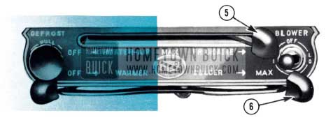
1956 Buick Air Conditioner Blower Controls
- “Frigidaire” – Moving the upper lever through this range to the extreme right “ON” position puts the compressor into operation and starts the air conditioner system when engine is running. By moving this lever from “MA X ” to “ON” position, it also closes the air outlet located midway underneath instrument panel and opens the right dash ventilator. During air conditioner operation the opened right dash vent permits return air from passenger compartment t o be mixed with filtered outside air. The mixture is then cooled before entering the passenger compartment.
- “Colder” – Moving the lower right lever through this range to the “MAX” position provides the greatest amount of cooling when the heater and defroster temperature control is in “OFF” position. The lever may be placed anywhere between “Colder” and “MAX” positions as desired to suit personal requirements.
- An air outlet mounted on center of instrument panel is equipped with a valve which may be raised or lowered as desired for upper level cooling. During heater operation, this valve should be closed completely.
1956 Buick Air Conditioner Outlet
In hot climates, when car is parked in the sun with the windows closed, it is recommended that the windows be opened for a short period of time to allow the accumulated heated air to be expelled. This will help your Air Conditioner to cool the car interior more quickly. Driving with transmission in “Low” range in city traffic for a short period after starting will also reduce cooling time.
During a rain, especially in mild climates when the temperature is low and the humidity is high, the Air Conditioner can be operated in conjunction with the heater by moving lower lever “Warmer” to the right. The Air Conditioner will dehumidify (dry) the air and the heater will then warm it.
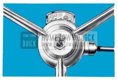
THE VARIABLE PITCH DVNAFLOW DRIVE
Control of the Variable Pitch Dynaflow Drive is obtained by positioning the control lever mounted directly below the steering wheel. Variable Pitch Dynaflow-equipped cars do not have a clutch pedal and lever may be placed in any position when engine is idling by merely moving the lever. Stops have been placed at certain points in the lever travel so that it is necessary to raise the lever to place it in certain positions. After a little experience driving the car, 1956 Buick Owners will find that it is possible to select a range merely by “feel” and visual reference to the dial will not be necessary. However, on all series the dial is illuminated for night driving and is controlled by the instrument panel lighting circuit.
When required, additional engine “braking” can be obtained by placing lever in “L”.
NOTE: The starting motor circuit on cars equipped with the Dynaflow Drive is so wired that the engine will not start unless the control/ever is in either” P” or” N” positions.
There are Five positions indicated –
1956 Buick Variable Pitch Dynaflow in P
“P” This is a Parking Lock and is to be used in conjunction with the foot operated “Step-on” parking brake. THIS PARKING LOCK MUST NEVER BE APPLIED WHEN CAR IS IN MOTION. Control lever must be raised to be placed in or out of this position. Parking the car with the control lever in “D,” “L,” or “R” positions will not partially brake the car as it does when 1956 Buick Owners leave a conventional transmission “in gear.
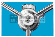
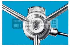
1956 Buick Variable Pitch Dynaflow in N
“N” This is neutral and is to be used when towing the car and may be used in stead of “P” when car is standing still and engine is running. Control lever must be raised when moving it from “D” to “N” position.
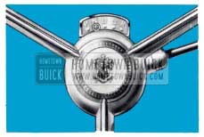
1956 Buick Variable Pitch Dynaflow in D
“D” This range is used for all normal forward driving After the engine has been started, place Control Lever in “D” position and depress accelerator pedal. Nothing more need be done.
The new converter with Variable Pitch Stator Blades enables the driver to select the efficient cruising position or the greater performance position by the normal operation of the accelerator pedal. An added resistance to the accelerator pedal operation is provided near the end of its travel. By fully depressing the pedal through this point the higher performance setting is achieved.
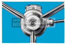
1956 Buick Variable Pitch Dynaflow in L
“L” This range is to be used when the “going” is particularly tough, such as deep snow, or sand, or on long steep grades. To operate in this range, simply move the control lever to “L” position and drive as before. This range may also be used for “braking” the car speed on long or steep down grades.
Operation of the Variable Pitch may be obtained in Low Range by depressing the accelerator pedal as explained under “D” above.
Maximum acceleration from a standing start is obtained by starting in “L” and shifting to “D” at 35M P.H. (ECONOMY NOTE: When driving Dynaflow cars, Buick owners have a choice of good performance with economy or superb performance. Good fuel economy may be obtained by making normal starts and not attempting to obtain maximum acceleration at all times. If, however, 1956 Buick Owners desire maximum performance on every start, 1956 Buick Owners must expect less fuel economy.)
The shift from “L” to “D” or vice versa may be made while the car is in forward motion by merely Flipping the lever. These shifts should not be made at speeds over 40 M.P.H.
1956 Buick Variable Pitch Dynaflow in R
“R” This position reverses the car motion. To operate with car standing, raise and move control lever to stop at bottom of lever travel. Depress accelerator pedal for backing car.
If Variable Pitch is required in Reverse, depress the accelerator pedal as explained in “D” and “L” above.
Pushing or Towing Car to Start Engine – If it becomes necessary to push a Dynaflow Drive car to start the engine, place shift control lever in Neutral (N) until car speed reaches approximately 15 MPH, then shift into Low (L). Continue to increase car speed until engine cranks (approx. 25 MPH). After engine starts, return control lever to Neutral (N) for engine warm up. It is safer to push car than tow it.
FOR PERIODIC MAINTENANCE AND LUBRICATION INSTRUCTIONS SEE GENERAL MAINTENANCE SECTION
ADJUSTABLE FRONT SEAT
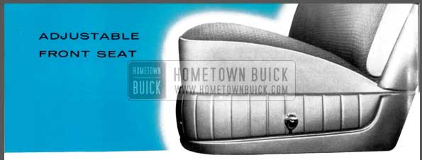
1956 Buick Adjustable Front Seat
The front seat on all Buick models is easily adjusted to any position forward or backward to provide maximum driving comfort. Manually operated seats may be adjusted by merely pressing the control lever at the driver’s end o f the seat and exerting slight body pressure either forward or backward. When in the desired position, the seat adjuster mechanism will automatically lock to prevent movement. On Models 52 and 72 only – if additional rearward movement is desired, an internal seat adjustment is provided and may be performed by your dealer.
1956 Buick Power Front Seat
A six-way power seat is available as optional equipment on all Buicks except model 48. Three (3) separate double-acting switches mounted on the left side of the front seat provide a means by which the seat may be adjusted in any on e of six directions: forward, rearward, up, down, tilted forward, or tilted rear ward. A forward or rearward movement is controlled by pressing the center button in the direction of desired travel. The seat may be raised or lowered at either the front or rear, or both, by merely pressing the corresponding outer buttons in the direction of desired travel. Tilting seat action may be acquired by raising the front end and lowering the rear or vice versa.
Forward or backward movement o f two-way power operated seats which are standard equipment on models 56-C 66-C 73, 76-C and 76-R is controlled by pressing a button on driver’s end of seat in direction of desired travel.
Easier rear seat entrance can be made on all two-door models due to the angular tilting split seat backs.
ADJUSTABLE ST EERING VVHEEL
The steering wheel on your Buick is adjustable “up” and “down” within certain limits. If the location of the wheel does not fit your particular needs, ask your dealer about changing it for you.
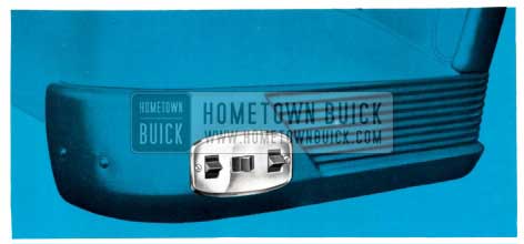
STEP-ON PARKING BRAKE
1956 Buick Parking Brake
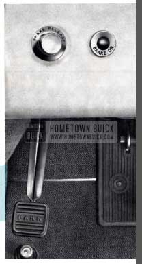
This is a mechanically operated brake which locks both rear wheels. This brake is operated with the foot and is located on the left side under the instrument panel.
This brake is self-locking and will remain applied until the knob marked “Brake Release”, located at lower left flange of instrument panel, is pulled out to release. This brake should always be released before the car is driven.
A red warning light on the instrument panel lights if the ignition is turned on and the brake is not released. (Standard on Roadmaster, Optional on Series 40, 50, and 60.)
POWER BRAKES
Power brakes operate in the same manner as conventional Buick hydraulic brakes, except that about a third of the effort required to apply the brakes is furnished by the power cylinder. In addition to the reduced effort required, the travel of the brake pedal is reduced by about one third.
The source of power to operate power brakes is furnished by the normal vacuum which is present in the intake manifold of the engine. A vacuum reservoir is provided in the pipe line from the power cylinder to the engine manifold. This tank insures instant response of the power cylinder when the brake pedal is depressed and also stores sufficient vacuum f or 2 or 3 power stops after the engine stops.
After the supply of vacuum in the reservoir has been expended, the brakes will function unassisted by power but will require higher pressure of the foot on the pedal .
FRAME JACKS – FOOT OPERATED
TO CHANGE REAR TIRES
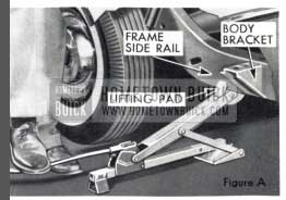
1956 Buick Change Rear Tires
- Set parking brake, remove hub cap and loosen wheel bolts.
- Place jack directly ahead of rear wheel and to rear of body bracket with lifting pad under Flat portion of side rail. See Figure A. This position can be seen between front of tire and fender.
TO CHANGE FRONT TIRES
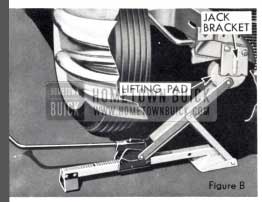
1956 Buick Change Front Tires
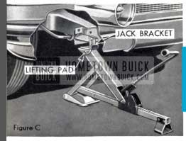
1956 Buick Jack Instruction
- Set parking brake and remove hub cap.
- Loosen all wheel bolts.
- Place jack just inside bumper guard with lifting pad securely under bracket attached to front end of side rail. This bracket can be seen between front o f tire and fender. Figures B and C show positions in which the jack may be used.
CAUTION: Jack must be placed under bracket to obtain necessary lifting height.
INSTRUCTIONS TO OPERATE FRAME JACKS
With trip lever in the vertical position the jack will raise the car with a down ward movement of jack handle. Jack can be operated by foot or hand. The socket end of handle should be in a horizontal position when being used as a jack handle.
The trip lever should be in a horizontal position to lower jack.
NOTE: Do not use front and rear bumpers or back bars for jacking purposes as subsequent damage to their related parts may result.
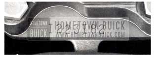
HOOD OPERATION
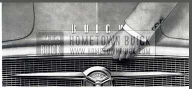
1956 Buick Hood Operation
The Buick hood is a conventional front-opening, spring counterbalanced hood of the so-called “alligator” type.
The hood latch is controlled from the front of the car by a Iift lever located between the radiator grille and the radiator grille header bar. To open the hood, locate the lever by placing the fingers under the header bar, slightly to the right of center. Lift or push upward Firmly and the hood latch will release the hood so that the fin9ers may be placed between the top of the header bar and bottom flange of the hood. To lift the hood place fingers between the header and hood at the center and locate the safety latch. Pull forward as far as possible and then raise hood by lifting upward. The hinge design makes it advantageous to pull forward as well as upward for easy raising of hood.
To close the hood, lower it to a near-closed position, then push firmly downward until the latch is fully engaged and the hood cannot be raised even slightly. If not properly locked, the hood will remain partly opened held only by the safety latch.
DIRECTION SIGNALS
To operate the turn signals, the ignition switch must First be turned on. The switch lever on the left of the steering column should then be pushed up for a right turn and down for a left turn. This action causes the front lamp and the stop light mounted at the extremity of the rear fender to Flash on that side of the car in the direction the turn is to be made. If stop lights are applied at the same time a turn is indicated, the opposite stop light will remain solid.
Verification of the proper functioning of both front and rear lamps is indicated by a flashing of one of the illuminated green arrows, located at the ends of the speedometer.
If the arrow does not light and Rash, after movement of the turn signal lever, it indicates that the signal system is not functioning properly and should be checked for burned out fuse, or bulbs in either front or rear signal lamps or the bulb which illuminates the green arrows.
Always indicate a turn at a reasonable distance before making the turn.
REAR COMPARTMENT
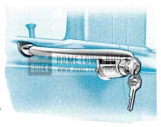
1956 Buick Trunk Handle
On series 40-60 models, the compartment lid lock is located directly below the rear compartment ornament. Insert and turn key (clockwise) and raise the compartment lid, using lower edge of ornament as a handle. To lock, firmly close lid.
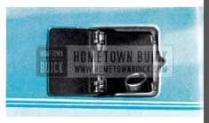
On series 50-70 models, the rear compartment lid lock is located in t he body rear end panel just below center of lid opening. The lid is un locked by simply turning the key in counter-clockwise direction.
BUICK RADIOS
SONOMATIC RADIOS
Switch and Volume Control (Left Knob)-The first portion of rotation in a clockwise direction turns on the radio. Further rotation increases volume.
Tone Control (Chrome Plated Lever Behind the Volume Control Knob) – Control in extreme “treble” position gives brilliant reproduction of the full tone range. This position will reproduce speech very clearly and distinctly. Rotation counterclockwise (toward “bass”) diminishes brilliance and accentuates low notes.
Tuning Control (Right Knob) – When tuning manually, or when setting up a station on one of the buttons, remember-If the program sounds shrill or distorted, it is probably caused by improper tuning and can be corrected by adjusting the tuning knob slightly. Since t he low notes are more affected by tuning than the high tones, it is a good plan to tune the set to a point where the low notes are heard best and the high notes are clear but not shrill.
IMPORTANT: In the event of a National Emergency when radio stations stop their scheduled programs, be sure to tune in important Civil Defense information broad cast for you by the Conelrad Plan. With the manual tuning knob, set the radio dial pointer on one of the small Civil Defense triangles at 640 or 1240 kilocycles!
PUSH BUTTON SET- UP
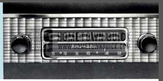
1956 Buick Sonomatic Radio
Setting the push buttons to tune to any desired station is a simple procedure requiring no tools or equipment.
Procedure is as follows:
- 1 . Turn on radio.
- Press button to left and at the same time pull it out as far as possible.
- With button out, tune in the desired station manually. (Do this very carefully as the push buttons will automatically repeat the tuning each time they are pushed. If incorrectly tuned when set up they will always be incorrect until setting is changed manually.)
- Push button in as far as possible. This automatically completes the button set-up and locks the mechanism in position.
SELECTRONIC RADIOS
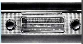
1956 Buick Selectronic Radio
Buick’s Selectronic Radio is an innovation in radio tuning and provides a simple method of station selection regardless of locality. Unlike the Sonomatic Buick Radio which automatically tunes known stations in a particular locality, the Selectronic set automatically and quickly tunes in stations all along the dial which fall within the signal strength limits set by the operator.
Signal strength limits may be set at any one of four positions by turning the sensitivity knob located behind the manual tuning knob to either “MORE” or “LESS”. Extreme movement of the knob toward “MORE” will include all available stat ions, provided the antenna is fully extended. By turning the knob to the extreme “LESS” position, nearly all stations are eliminated except strong local stations.
After setting the sensitivity control knob at any one of the four positions, turn on the set and move the dial indicator by either pressing the foot switch or the selector bar on the front of the set . Touch either momentarily and the dial indicator will automatically move to the next station on the dial having sufficient signal strength to fall within the range for which the sensitivity control is set. By repeating this operation intermittently, the dial indicator will “search” the entire width of the dial and automatically return to the low frequency end of the dial ready to “search” the entire dial again.
Volume is controlled by the knob at the left end of the dial. By simply turning the knob clockwise, volume may be increased. Varying degrees of tone between treble and bass are obtained by turning the knob behind the volume control knob as indicated.
In some cases, when it is desirable to tune the set manually, simply operate the manual tuning knob at the right of the dial as with any conventional radio.
(Both radios) – The Buick radio antenna is located on the left front fender opposite the windshield. The “manually-operated” antenna must be raised and lowered by hand.
The “electrically operated” antenna (optional equipment on all models) may be raised or lowered from inside the car even while driving. A toggle switch mounted on the lower edge of the instrument panel to the left of the steering column raises the antenna when pulled toward the driver and lowers the antenna when pushed forward. For satisfactory radio operation, the antenna should be fully extended.
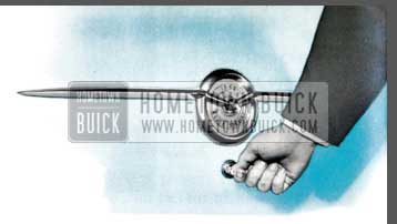
ELECTRIC CLOCK
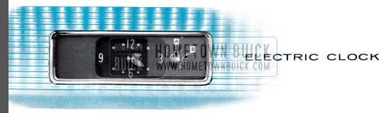
1956 Buick Clock
To reset clock, pull knob “A” at right side of clock out and turn in desired direction.
To regulate the clock for more accurate timekeeping, place small screwdriver or similar tool in slot in small knob “B” behind the reset knob and turn toward “F” if clock is running slow, or toward “S” if clock is running fast. It is advisable to move the regulator only one division or graduation at a time. By following this procedure your clock may be regulated to keep exceptionally close time.
IMPORTANT: The electric clock requires special attention when reconnecting a battery that has been disconnected for any reason, a clock that has been disconnected, or when replacing a blown fuse. IT IS VERY IMPORT ANT THAT THE INITIAL WIND BE FULLY MADE.
To be certain of this, proceed as follows:
(1) Make sure that all other instruments and lights are off. (2) Connect one terminal of the battery first.
Before permanently connecting the other cable, touch the terminal to its post on the battery. Immediately afterward strike the terminal again to see if there is a spark. If there is, allow the clock to run down until it stops ticking and repeat as above until there is no spark. Then immediately make the permanent connection before the clock can again run down. The clock will run down in approximately 2 minutes.
The above procedure should also be followed when reconnecting the clock after connections have been removed, or when replacing a blown fuse. Be sure to disconnect the battery cable before installing new fuse.
Failure of clock to run may be caused by any of the following:
Blown fuse-discharged battery-corroded battery terminals -wire improperly connected to fuse block or terminal connection to back of clock-or defective clock.
In replacing fuse, use only 2-ampere AGA fuse on all Series.
TIRES
Your Buick is equipped with tubeless tires mounted on disc wheels. These tires resist blow-out from impact breaks and give a slow loss of air instead of a blow-out. Puncture sealant is not specified in these tubeless tires; however, air loss due to a puncture is much slower from a tubeless tire and a nail can usually be left in until a service station can be reached. Tires should be inspected periodically, preferably each time the car receives Lubricare, and puncturing objects removed.
When puncturing objects are removed, repairs will have to be made according to recommendations of the tire manufacturer.
For maximum tire service-keep tires properly inflated-use an accurate gauge-after inflating, be sure valve caps are in place and screwed down fingertight.
EXTRA LOW PRESSURE TIRES
Use air pressure as indicated below for checking proper inflation.

1956 Buick Tire Over Inflation
1956 Buick Tire Under Inflation

1956 Buick Tire Proper Inflation
24 Lbs. (starting pressure) AFTER the car has been standing for three hours or driven less than a mile.
26 Lbs. (city pressure) AFTER driving the car three miles or more BELOW 40 miles per hour.
28 Lbs. (highway pressure) AFTER driving the car three miles or .more ABOVE 40 miles per hour.
It is normal for air pressure to build up in o tire clue to driving conditions.
DO NOT LET AIR OUT OF TIRES TO REDUCE THIS INCREASE IN PRESSURE
EQUALIZE WEAR ON TIRES
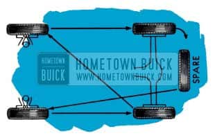
1956 Buick Tire Wear
CHANGE TIRES TO POSITIONS SHOWN IN DIAGRAM ABOVE AT LEAST EVERY 4000 MILES.
This change of position helps out uneven wear on front tires and distributes the faster wear on the rear tires over all five tires.
CLEANING WHITE SIDEWALLS
Use mild soap, warm water, and stiff brush to remove road grime and curb dirt from white sidewall tires.
Use medium or fine steel wool for severe cases.
Do not use gasoline, kerosene, or any oil product that w ill discolor the sidewalls and rot the rubber.
By comparing air pressure in all tires, any variation in pressures will be evident. To prevent flat tires, investigate and correct a continued loss of air in any tire.
CONVERTIBLE COUPE
1956 Buick Power Convertible Top
The power operating switch for raising or lowering t op is located on lower flange of instrument panel at right of steering column.
TO LOWER TOP
- Stop car.
- Release catch above windshield.
CAUTION: Before operating power top control button make certain that the top directly above the windshield is raised slightly in order to clear windshield dowels. Close catch.
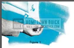
- With ignition switch on, pull control knob a way from panel and hold until t op is completely lowered. Fig. 1.
- After top is lowered, raise it slightly by hand and pull the t op material and padding out from under the roof bow so that it lays in position shown. Fig. 2.
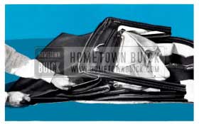
1956 Buick Convertible Top Operation
1956 Buick Raise Convertible Top
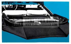
TO RAISE TOP
- Stop car.
- Remove top boot and unfasten hold down strap.
- Push t op control knob f or ward and hold until top is fully raised.
- Draw top down over windshield header dowel s and fasten catch to lock top.
To keep mechanism in good condition the top should be operated at least once a month. CAUTION: DO NOT OPERATE EITHER UP OR DOWN WHILE CAR IS IN MOTION.
If top is to be left folded for any length of time it should be securely strapped down to prevent chafing of top material. Also, boot should be installed to keep top clean and dry.
Wiring for power-operated top, side windows and front seat is protected by a 30 ampere circuit breaker having automatic reset.
CARE OF CONVERTIBLE MODEL TOPS – The ONLY METHOD RECOMMENDED for cleaning convertible top material is the use of lukewarm (not hot) water, and a mild (not caustic) soap. The top should be cleaned carefully from end to end using a medium stiff brush or sponge. Do not saturate at any point. Do not fold top when wet. Frequent brushing with an ordinary upholstery brush or stiff whisk broom is helpful in preventing dust and dirt from imbedding itself in the fabric.
CARE OF PLASTIC BACK WINDOW – To avoid scratches t o which the back window is susceptible, use only a soft cotton cloth moistened with tepid (not hot) water and mild (not caustic) soap. Rinse with clean water and dry wit h a slightly moistened soft, clean cloth. NO OTHER CLEANING METHOD IS RECOMMENDED.
POWER OPERATED WINDOWS
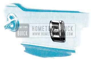
1956 Buick Power Windows
Each panel is equipped with an operating button which i s pushed down to lower the window, and pushed u p to raise the window.
ESTATE WAGON
FOLDING REAR SEAT
Adjust front seat forward and open each rear door before folding rear seat cushion and back . This will prevent scuffing t he seat back.
ENGINE AND SERIAL NUMBERS
There are two numbers which identify your car. They are recorded by the License Bureau of the state in which your car is licensed.
SERIAL NUMBER – ALL SERIES

1956 Buick Serial Number Location
The serial number is located on a plate affixed to the left front pillar post below the belt molding line and is visible by opening the left front door.
ENGINE NUMBER
1956 Buick Engine Number Location
The engine number is located on the outside of the left bank of cylinders on an extension of the top face of the block, halfway back.
BATTERY
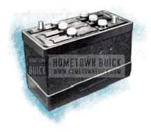
1956 Buick Battery
CAUTION-Electric storage batteries give off highly inflammable hydrogen gas when charging and continue to do so for some time after receiving a steady charge .
Under no condition should an electric spark or an open flame be allowed near t he battery, particularly in the vicinity of the vent caps.
Before doing any work around a battery a metallic contact between the car bumper and t he ground should be made t o remove the possibility of a static charge causing a spark in the vicinity of the battery. A long metal bar or a metal chain of sufficient length will accomplish this.
COOLING SYSTEM
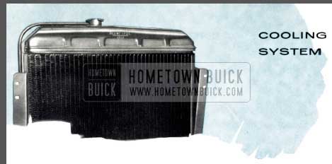
1956 Buick Radiator
The Buick cooling system is a sealed pressure type which raises the coolant boiling point. There is no need to check coolant level as long as the operating temperature remains normal . Never check level until the engine has been stopped for several minutes. When checking level, always remove cap slowly t o be sure the engine has cooled enough to remove the pressure even at normal temperatures.
The system should be drained twice a year. It is important that a rust preventive be added when refilling. Proper coolant level is stamped on the radiator tank as shown – DO NOT FILL ABOVE THIS LINE.
CAUTION – When installing anti-freeze, do not use solutions that contain salt, oils, kerosene, glucose or honey.
The cooling system has been treated a t the factory with a special patented stop leak and inhibitor.
If, for any reason, the system is ever completely drained, “Buick Radiator Stop Leak and Cooling System Conditioner,” Part No. 981441, should be added for maximum protection .
CLUTCH ADJUSTMENT
SYNCHRO-MESH TRANSMISSION
There should be 3/4 of an inch to 1 inch “lash” or free movement in the clutch pedal at all times.
Unless some “lash” is maintained the clutch may slip, necessitating replacement of clutch parts due to excessive heat and wear.
CARE OF CHROME AND FINISH
Calcium chloride and other salts, road tar, excretion from insects, tree sap, chemicals from factory chimneys and other foreign matter may permanently damage the finish of cars.
Frequent, regular washing thorough c leaning and waxing after exposure is recommended to prevent damage by these substances.
LAMP BULBS
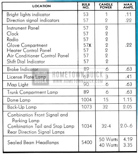
1956 Buick Lamp Bulbs
FREE WHEELING DOOR LOCKS
The rear door locks on four-door sedans are designed and are set so that the inside handles “free-wheel” when the locking button is pushed down into lock position. This prevents children from accidentally opening the rear doors. The feature ca n be changed by any Buick Dealer if it is not desired.
When lock is set for free- wheeling it is necessary t o raise the lock button before either the inside or outside handles will open the door.
FUSES
| USED FOR: | TYPE: | LOCATION: |
| Clock | 2 Amp. AGAor 1 AG |
In fuse block mounted between lower Range of instrument panel and dash at left of steering column. |
| Blower Motor | 20 Amp. SFE | |
| Stop LampsDirection Signal Lamp(Front & Rear) | 9 Amp. SFE | |
| Air-Conditioner CompressorClutch | 5 Amp.3 AG or AGC | |
| Back-Up Lamps andBrake Warning | 10 Amp. AGCor 3 AG | |
| Dome LampTrunk Compartment | 20 Amp. SFE | |
| Glove Box and Map Light | 2 Amp. AGAor 1 AG | Line connector type opposite Glove Box |
| Radio | 7.5 Amp. Special | Line connector at left of radio. |
| Cigar lighter-Front | Special Fuse | In back of lighter socket |
| Cigar lighter -Rear | Dome lamp fuse | In back of lighter socket and fuse block. |
| Electric Antenna | 15 Amp. AGCor 3 AG | Line connector near fuse block. |
| Head Lamps Tail Lamps Parking LampsInstrument Lights | Thermal Relay System* | |
*THERMAL RELAY – There are no fuses i n the headlamp, tail lamp, parking lamp or instrument lamp circuits.
Protection for these circuits is through a thermostatically controlled current limit relay attached to light switch. When t h e current load is too heavy, due to a short circuit, the relay opens and closes rapidly thus reducing current sufficiently to protect the wiring from damage. This action continues until the cause is eliminated.
SPECIFICATIONS AND DATA
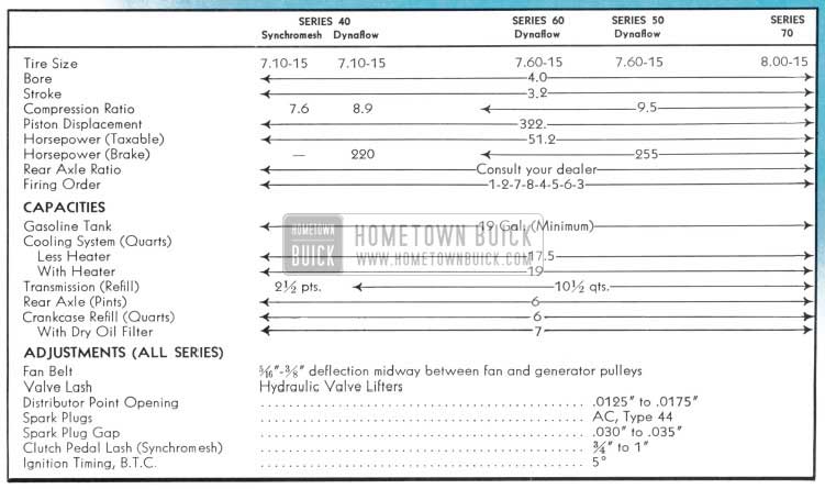
1956 Buick Specifications and Data
GENERAL MAINTENANCE
ENGINE OIL
For instructions on maintaining proper oil level see Page 4.
The crankcase oil put in at the factory is a high quality Service M.S. oil (see below) with special break-in additives; so it should be left in for the first 1000 miles.
Ordinarily, no further break-in oils or additives are needed. However, under some adverse driving conditions if such additives are necessary, your Buick dealer has available Buick Engineer-approved products for your use.
Oil should be normally changed after the first 1,000 miles (see Page 34 for filter service) and every 2,000 to 3,000 miles thereafter. Certain types of operation however, such as short run, low speed operation in cold weather or in metropolitan areas where driving is limited to ten to twenty miles per day, or in extremely dusty territory, calls for more frequent changing. If there is any question about the change interval best suited for your type of driving, please consult your Buick dealer.
There are several types of oil manufactured for use in internal combustion engines. For use in the Buick engine we recommend that an oil, designated “For Service DG” or “For Service MS” (formerly called heavy duty type) be used for maximum protection under all driving conditions. “For Service ML” (formerly called regular type) and “For Service MM” (formerly called premium type) are not recommended for use in Bu1ck engines.
Engine crankcase oils have a definite effect on ease of starting, oil economy, combustion chamber deposits and engine wear. Many commercial crankcase oils contain heavy non-volatile deposits forming components which make the type of combustion chamber deposits that greatly increase detonation and particularly pre-ignition, even though these oils may be designated “For Service MS” or “For Service DG. ” Some commercial crankcase oils are deficient in anti-wear characteristics and may contribute to rapid wear of camshafts, valve lifter assemblies and other highly stressed engine parts. Owners are urged to use only crankcase oils that have proven to produce ease of starting, satisfactory oil economy, minimizing combustion chamber deposits and produce adequate protection against wear.
The following chart will serve as a guide for the selection of the correct SAE viscosity number oil to use under specified atmospheric temperature ranges:
| TerritoryTemperature Spec. | SingleViscosity Oil | Multi– ViscosityOil |
| Not lower than +32° F. | SAE 20 or 20W | SAE lOW-30 or SAE lOW-20 |
| Not lower than -10° F. | SAE 10W | S AE lOW-30 or SAE lOW-20 |
| Below -10° F. | SAE SW | S AE SW-IOW or SAE SW-20 |
EVERY 1000 MILES
Chassis – Wipe dirt from lubrication fittings, then apply a good grade of water-resistant chassis lubricant, under pressure, at the following points: (1) Lower Control Arms, inner and outer ends, (2) Upper Control Arms, (3) Steering Knuckles, (4) Tie Rods and Intermediate Rod, Steering linkage idler arm bushing, (5) Clutch Release Equalizer, (6) Clutch and throttle linkage may be lubricated (up to carburet or throttle rod only) with engine oil.
Synchromesh Transmission and Rear Axle – Check level at filler plug. Maintain level using SAE 90 Multi-Purpose Gear Lubricant (U.S. Army Spec. 2-1058) for temperatures not lower than 10°F below zero. In temperatures continuously below -10°F, use S AE 80. Seasonal or periodic draining and flushing is not required. When complete refilling is required, however, use above lubricant in transmission but use only Factory Hypoid Lubricant in rear axle.
Dynaflow Drive – Check Transmission oil level , with transmission oil warm, transmission in Parking and engine idling. If Ievel is more than one inch below “FULL” mark on gauge rod, add oil but do not fill above the “FULL” mark. Distance between “FULL” and “ADD OIL” marks on rod represents one pint. Use oil specified under “Every 25 ,000 Miles. ”
Manual Steering Gear – Check level at filler plug. Maintain level using Multi-Purpose Gear Lubricant as recommended f or rear axle. Do not use pressure when filling. Seasonal or periodic change of lubricant is unnecessary.
Power Steering Gear – All models use a pump having an integral reservoir which supplies all necessary lubrication to the system. To check oil level, remove cover or cap from reservoir and see if oil comes to specified level mark. Add oil specified for Dynaflow Drive to maintain level.
Cranking Motor (Starter) – Apply a few drops of engine oil to the link pins and fulcrum stud of shift yoke.
Battery – Add distilled water to bring level to ledge at bottom of slot in well.
WARNING: Do not fill above ledge.
Air Cleaner – Normally serviced every 5000 miles. If car is operating in dusty territory, however, check condition of air cleaner and clean it if dirty. See cleaning and filling instructions under “Every 5000 Miles.”
Radiator – Check coolant level only when radiator is cold. Maintain level at line on tank marked, “Filling Level -Cold,” using water. Filling above level line or when radiator is hot will cause loss of coolant.
CAUTION: Do not remove cap when radiator is hot because coolant will boil and overflow when pressure is released. When refilling cooling system after draining, Temperature Control lever must be moved to extreme right posit ion.
NOTE: If cooling system is being drained for storage where freezing is likely to occur, it is necessary to disconnect heater and defroster hoses to thoroughly drain them.
Manifold Valve Shaft – Place a few drops of graphited kerosene on shaft at each end and rotate shaft to work lubricant into bearings. If shaft is frozen, free up by tapping ends of shaft lightly with hammer.
Throttle Control Linkage – Place a few drops of engine oil at connections. Work Lubriplate into Equalizer Shaft bearings and wipe off surplus lubricant.
Generator – Place a few drops of engine oil in cups at both ends of generator. Avoid excessive oiling which may affect brushes and windings. Do not lubricate while generator is in operation.
Master Brake Cylinder – Thoroughly clean filler cap nut before removal to avoid getting dirt into reservoir. Add fluid as required to bring level to 1/2″ to 1″ below top of filler opening. Use G.M. or Delco Super No. 11 Hydraulic Brake Fluid. NEVER USE RECLAIMED FLUID OR ANY MINERAL OIL.
Tires – Inflate all tires to pressures given on page 22.
WARNING: It is not possible to inflate tires correctly when they are hot.
Hood Fastener Mechanism – Lightly coat latch lever and pilot with Lubriplate.
Door Locks and Strikers – On Series 40-60 and Models 53-73 apply G.M. Door-Ease Lubricant at the following points: (1) Top of bolt housing; (2) Gear teeth on striker. On Series 50-70, except Models 53-73, apply G.M. Door-Ease Lubricant on (1) Wedge plate on lock; (2) Wedge contact surface on striker. Use only S.A.E. 10 engine oil on lock bolt roller.
Door Checks and Hinges – On Series 40-60, 50-70, apply Lubriplate or chassis lubricant to hold-open springs in front door hinges. Use same lubricant sparingly on lugs of all rear door check links. On check link pins of rear doors use Lubriplate. No lubricant required on hinge pins.
Dome Lamp Door Switches – Apply G.M. Door-Ease Lubricant to end of switch plunger and point of contact on door hinge pillar.
Glove Box Door – Apply a few drops of light engine oil to glove box door hinges -wipe off surplus oil. Sparingly coat lock striker with G.M. Door-Ease Lubricant.
Windshield Wiper Cables – Wipe a few drops of light engine oil on cables where they pass over tensioner pulleys.
CAUTION: WINDSHIELD WIPER BLADES MUST NOT BE ROT A TED BY HAND FOR ANY REASON AS THIS PLACES AN UNDUE STRAIN ON CABLE FASTENINGS.
Gas Tank Filler Door – Apply a few drops of light engine or penetrating oil on the hinge pins. Wipe off excess to prevent accumulation of fine dust and dirt.
Rear Compartment Lid Lock – Lightly coat lock latch and lock striker with Lubriplate.
Lock Cylinders – If key operates roughly in lock cylinder, blow powdered graphite into key slot. DO NOT USE OIL.
FIRST 2000 MILES
Lights – Check all lights and aiming of headlamps.
EVERY 5000 MILES
Distributor – Remove distributor cap and rotor. Apply a few drops of light engine oil to felt wick in top of cam. Put 1 drop of oil on breaker arm pivot. Work a small amount o f M-1172 ball bearing grease into a cloth, then hold cloth on distributor cam while engine is being cranked.
CAUTION: AN EXCESSIVE AMOUNT OF GREASE WILL THROW OFF WHEN HOT AND INSULATE THE CONTACT POINTS, CAUSING IGNITION FAILURE.
Air Cleaner – Every 5000 miles (more often under dusty operating conditions) disassemble air cleaner and wash cleaner element and oil sump with a non-inflammable solvent (kerosene is not recommended). Wipe sump dry and allow cleaner element to drain until dry. DO NOT USE AIR BLAST ON CLEANER ELEMENT. Fill sump to indicated level with one pint SAE 50 engine oil and assemble air cleaner. DO NOT OIL THE CLEANER ELEMENT BECAUSE OIL WILL DRAIN BACK INTO THE SUMP AND CAUSE SUMP TO BE OVERFULL.
Crankcase Ventilator Filler Caps – Every 5000 miles or so, depending on driving conditions, clean and reoil, using the current viscosity engine oil.
Fuel Filter – Drain and if necessary clean or replace element as required t o remove accumulated foreign matter. Refilling will be automatic as quickly as engine starts.
Oil Filter – Change oil filter element at first 1000 miles, then 5000 miles and each 5000 miles thereafter. * Remove old element, and wipe container out thoroughly with CLEAN cloths. Install new element and new cover gasket. Use only Buick Oil Filter Replacement Element Part No. 5572128 (AC PF-122), or equivalent.
*In extremely dusty areas , more frequent change may be desirable.
Pump Operating Countershaft – Carter Carburetor Only-Remove the two dust cover attaching screws and apply several drops of engine oil in screw holes above countershaft. Install screws.
Horn Cable Connector – Pull out plunger and apply a small amount of Lubriplate. Work plunger in and out.
Lights – Check all lights and aiming of headlamps.
EVERY 10000 MILES
Front Wheel Bearings – Wipe old grease out of hub and wash bearings. Work approximately one tablespoon of wheel bearing lubricant into each ball bearing. The oil seal packings should be examined for wear or leaking and replaced if necessary.
NOTE: Do not overfill bearings as excessive lubricant may be forced thru seals and get on brake lining.
Bearing Adjustment – Take up spindle nut with 10″ wrench until bearings are preloaded at least 1 hex, then rotate wheel 1 revolution to make sure bearings are seated. Back off spindle nut until bearings are loose. Tighten nut until all bearing looseness is just removed, then line up nut to nearest cotter hole and install cotter pin. Do not mistake loose king pin bushing, etc., for wheel bearing looseness.
CAUTION: BEARING PRELOAD MUST NOT EXCEED 1/12 TURN OF NUT.
EVERY 25000 MILES
Dynaflow Transmission – At 25,000 mile intervals the oil pan and torque converter should be completely drained and re-filled with fresh oil. Transmission MUST NOT BE FLUSHED when oil is changed. Use Special Buick Oil for Dynaflow Drive or any Automatic Transmission Fluid, Type A, which has an AO-ATF identification number embossed in lid of container.
Put in 3 quarts of specified oil. With engine idling in Parking, complete the refilling to bring oil level to 1 3/4″ below “FULL” mark on gauge rod. When transmission oil is warmed up, the oil level should then be at “FULL” mark on gauge rod.
AS REQUIRED
Rear Wheel Bearings – Rear wheel bearings need not be lubricated. Whenever axle shafts are removed it is advisable to inspect rear w heel bearings and oil seals. Replace seals if leaking or worn.
Speedometer Cable – The speedometer cable is factory lubricated with special grease and normally requires no further service unless it becomes noisy. In extremely hot climates, or where considerable dust and water is encountered it may be necessary t o lubricate the cable at interval s of approximately 20,000 miles or every two years . It is advisable to have this service performed by an Authorized Buick Dealer to insure use of the special grease in proper quantity.
Sunshade – If sunshade rod turns hard in support , remove retainer screw, pull rod from support and apply G.M. Door-Ease Lubricant.
Do not use oil which may soil trim. Install rod in support and adjust retainer screw to proper tension.
Cleaning Leather – (1) Apply a damp (not wet) cloth to mild soap and rub surface of leather briskly. (2) Wipe with moist cloth without soap. (3) Rub dry with clean, soft cloth.
TRAILERS
Should 1956 Buick Owners contemplate hauling a house trailer with their Buick, it is advisable that 1956 Buick Owners follow our instructions covering weight limits, springs, tires, and hitch specifications. To obtain this information, write Buick Motor Division, Service Department, Flint, Mich.
MODELS, WHEELBASES AND LENGTHS
SPECIAL SERIES 40
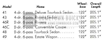
1956 Buick Special Series Wheelbase and Length
SUPER SERIES 50
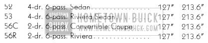
1956 Buick Super Series Wheelbase and Length
CENTURY SERIES 60
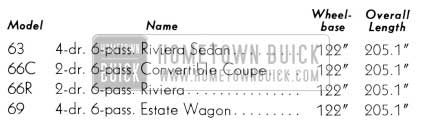
1956 Buick Century Series Wheelbase and Length
ROADMASTER SERIES 70
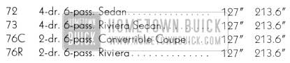
1956 Buick Roadmaster Series Wheelbase and Length
License Weight: Consult the dealer who sold the car to the original 1956 Buick Owners or the Motor Vehicle Commissioner of your State. Weights of all Buick body styles are regularly supplied to these authorities.
I can still remember when headlight dimmer switch was on the floorboard and you clicked it with your left foot our 1958 Pontiac Stattion Wagon had it this way
My first car I drove was 1956 Buick Century. 255 horse was a lot in 1956. It would haulass. Memories….