Project Description
1953 Buick Owners Guide
KEYS AND LOCKS
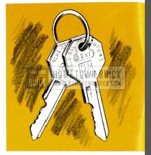
1953 Buick Keys and Locks
Identical keys operate all the locks on your Buick. Remove the “Knock-out” number and keep it in a safe place, to be used if your keys are lost or mislaid and duplicates are required. To lock the ignition, turn the key to “lock”; to shut off the ignition but still leave it operative with the key removed, turn the key to “off”. The car may then be operated yet the privacy of the glove and trunk compartments retained.
Lock the ignition and the doors of your car when leaving it unattended. Over 75% of the vehicles stolen have been left either with t he key in the ignition lock or unlocked.
AUTOMATIC STARTING SYSTEM
When the engine is cold, depress the accelerator pedal just far enough to engage the starter. I f the engine is warm, hot, or partially flooded, and does not start readily, depress the accelerator pedal to the floor and hold it there until the engine fires regularly. Always, in starting, be sure the shift lever is in “neutral”. On Dynaflow Drive cars, starter will not operate unless control lever is in “N” or “P”.
CAUTION: I t is possible to damage certain parts of the radio if the starter is engaged while the radio is on. As an added precaution, do not attempt to start the engine unless the radio is off. The radio switch may be turned on after the engine is running.
BREAK-IN PERIOD
For driving speeds up to 50 miles per hour no special break-in precautions are necessary. Driving speeds above 50 miles per hour should be avoided for t he first 500 miles, and any sustained speeds above 50 miles per hour should be avoided until the car has been driven 1,000 miles, although speeds up to 70 miles per hour may be used for short distances if desired. Warming the engine allow speeds allows all par t s to expand more uniformly to operating clearances.
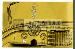
LIGHTS

1953 Buick Lights
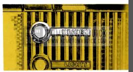
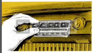
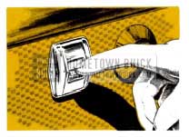
Headlights, parking lights, instrument lights, and map lights are controlled from a single four-way switch marked “LIGHTS” located at the left of the radio grille. There are two “out” positions in the switch obtained by pulling the circular knob. The first step turns on the parking lights and the second step controls the headlights. Instrument lights and map lights may be turned on in either step by simply turning the knob. In the extreme left position, both instrument and map lights are “off”. By turning the knob to the right, on e step, the map lights are “on”. The next step to the right ill0minates the instrument panel. Continued turning to the right diminishes the intensity of the instrument panel lights. All lights may be turned “off ” by simply pushing the control knob all the way in. It is not necessary to turn the knob in either direction before pushing in the knob. When pulled out again, instrument or map lights will be illuminated as previously.
The lower and upper beams of the headlights for city and country driving are controlled by a foot – operated switch located on the car door adjustment to the position of the left foot. When the upper beam is in use, a small red light is illuminated on the speedometer just above the “50” mark on Series 50 and 70 cars and in the center of the light indicator emblem, located between the two instrument clusters, on Series 40 cars.
WINDSHIELD WIPERS
1953 Buick Windshield Wipers
Vacuum-operated wipers are used for cleaning a large vision area on windshield glasses.
Adjustable speed control is had by turning a knob located on lower edge of instrument panel at left of steering column.
OIL SELECTION
In the selection of the proper brand of oil it is essential to consider the reputation of the refiner or marketer.
There are several types of oil manufactured for use in internal combustion engines. For use in the Buick engine we recommend that an oil marked “For Service MS ” (formerly called heavy duty) be used for maximum protection under all driving conditions. If Service MS oils are not available those marked “For Service MM” (formerly called premium oils) may be used. Oils marked “For Service ML” (formerly called regular oil) are not recommended in any Buick engine.
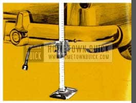
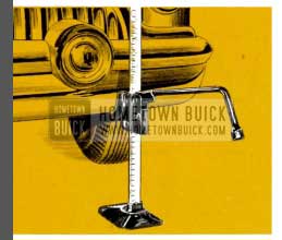
MAINTAINING PROPER LEVEL
The space between the Full line and the bottom line on oil gage rod represents two quarts. Always allow car to stand with engine off for from two to five minutes before checking level.
The oil level should be maintained between the lines. DO NOT OVERFILL. For proper S.A.E. grade of oil to use see page 24.
It is imperative that the same brand of oil be used at all times.
HEATER AND DEFROSTER
OUTSIDE AIR HEATING
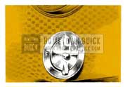
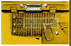
1 Set the Thermostat, marked “Heater Control,” (located at the bottom center of the radio grille) for the heat you want. Push lever to left for higher temperature and to the right for lower temperature or “OFF”. Temperature you set is kept even and constant -automatically-by controlling both the outside air heater and undersea! heater.
2 Pull the knob-marked “Defroster”-to send warmed outside air through upper level of car.
3 Turn “Defroster” knob to right for forced draft of warmed outside air through car’s upper level at slow car speeds, or when stopped.
NOTE: To keep out offensive traffic odors and exhaust gases when traveling in congested traffic or when parked behind a car having its motor running, close both “Ventilation” knobs and “Defroster” knob and turn off defroster blower. Exhaust gases contain carbon monoxide. See note inside back cover.
FLOOR LEVEL HEATING
1953 Buick Heater
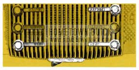
4 Turn the switch-marked “Heater “- for floor-level heating of car on all models. This is a two-speed switch, the first position to the right being high, the second position to the right being low. Now you have two-level heating, with uniform warmth in all areas of the car’s interior.
It is possible to send warmed outside air through the lower level of car without using the heater switch by setting the Heater Control to the temperature desired and pulling out the knob marked “Ventilation” on the right side of the radio grille.
SUMMER VENTILATION
5 Push in “Defroster” knob and make sure Heater Control is at “OFF”. Then pull either or both of the knobs -marked “Ventilation”. “Ventilation” knob on left directs large volume of outside air to driver side; “Ventilation” knob on right directs outside air to passenger side.
On Series 50 and 70 the direction of the air entering via the right hand ventilator may be controlled by the position of the ventilator control knob. The knob in the extreme out position causes the air to be deflected to ankle level. The knob when just short of the closed position permits non-deflected air to enter at approximately knee level. Intermediate settings of the knob will direct air at any angle between the two extremes mentioned above.
For additional driver and passenger comfort in the warmest of weather, while the car is motionless or while driving at slow speeds, simply turn “Defroster” knob to the right to start blower. This force-Rows a constant stream of outside air through out the car. See note on page 4.
6 For complete circulation, keep ventipanes open slightly to insure constant Row of air through the car, even when it’s raining and windows are normally closed
DEFROSTING
7 For windshield and all-window defrosting only, push in both “Ventilation” knobs, pull out “Defroster” knob, and set the thermostat control for the temperature 1953 Buick Owners want.
8 With outside air heating in use as described above under “Heating”, defrosting of all windows of course, is automatic.. For maximum defrosting push heater control lever to the left on “High” position and turn “Defroster” knob to right to turn on blower.
1953 Buick Defroster
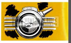
9 For defogging windows in summer months or during conditions of high humidity when no heat is desired, just pull out the “Defroster ” knob and turn to right. This insures clear vision through all windows.
SPECIAL NOTE: For satisfactory heating and defrosting it is essential that one or two ventipanes be opened slightly to exhaust old air and permit free circulation of new heated air.
THE TWIN TURBINE DYNAFLOW DRIVE
Control of the Twin Turbine Dynaflow Drive is obtained by positioning the control lever mounted directly below the steering wheel. Twin Turbine Dynaflow cars do not have a clutch pedal and lever may be placed in any position when engine is idling by merely moving the lever. Stops have been placed at certain points in the lever travel so that it is necessary to raise the lever to place it in certain positions. After a little experience driving the car, 1953 Buick Owners will find that it is possible to select a range merely by “feel” and visual reference to the dial will not be necessary.
When required, additional engine “braking” can be obtained by placing lever in “L”.
NOTE: The starting motor circuit on can equipped with the Dynaflow Drive is so wired that the engine will not start unless the control lever is in either “P” or “N” positions.
There are five positions indicated:
1953 Buick Dynaflow in P
“P” This is a Parking Lock and is to be used in conjunction with the fool operated “Step-on” parking brake. THIS PARKING LOCK MUST NEVER BE APPLIED WHEN CAR IS IN MOTION. Control lever must be raised to be placed in or out of this position. Parking the car with the control lever in “D”, “L”, or “R ” positions will not partially brake the car as it does when 1953 Buick Owners leave a conventional transmission “in gear.
1953 Buick Dynaflow in N
“N” This is neutral and is to be used when towing the car and may be used instead of “P” when car is standing still and engine is running. Control lever must be raised when moving it from “D” to “N” position.
1953 Buick Dynaflow in D
“D” This range is used for all normal forward driving. After engine has been started, place control lever in “D” position and depress accelerator pedal. Nothing more need be done.
1953 Buick Dynaflow in L
“L” This range is to be used when the “going” is particularly tough, such as deep snow, or sand, or on long steep grades. To operate in this range, simply move the control lever to “L” position and drive as before. This range may also be used for “braking” the car speed on long or steep down grades.
Maximum acceleration from a standing start is obtained by starting in “L” and shifting to “D” at 35 M.P.H. (ECONOMY NOTE: When driving Dynaflow cars, Buick owner have a choice of good performance with economy or superb performance. Good fuel economy may be obtained by making normal starts and not attempting to obtain maximum acceleration at all times. If, however, 1953 Buick Owners desire maximum performance on every start, 1953 Buick Owners must expect less fuel economy.)
The shift from “”L” to “” D” or vice versa may be made while the car is in forward motion by merely Ripping the lever. These shifts should not be made at speeds over 40 M.P.H.
1953 Buick Dynaflow in R
“R” This position reverses the car motion. To operate with car standing, raise and move control lever to stop at bottom of lever travel. De press accelerator pedal for backing car.
Pushing or Towing Car to Start Engine – If it becomes necessary to push a Dynaflow Drive car to start the engine, place shift control lever in Neutral (N) until car speed reaches approximately 15 MPH, then shift into Low (L). Continue to increase car speed until engine cranks (approx. 25 MPH). After engine starts, return control lever to Neutral (N) for engine warm up. It is safer to push car than tow it.
FOR PERIODIC MAINTENANCE AND LUBRICATION INSTRUCTIONS SEE GENERAL MAINTENANCE SECTION
FUEL SELECTION
1953 Buick Fuel
As in your selection of motor oil, consider the refinery or marketer in choosing the gasoline for your Buick. Most gasolines will perform satisfactorily but in some cases such as high temperatures or carbon accumulations, a premium gasoline will pro duce less detonation or “spark rap”. Normal detonation or “spark rap” is not harmful.
Series 40 Buicks equipped with Synchro-Mesh transmission may use REGULAR fuel, while compression ratios in Series 40 cars equipped with Dynaflow Drive and in Series 50 and 70 cars are sufficiently high to fully utilize PREMIUM fuels, and the most satisfactory performance will be obtained through their use.
WINDSHIELD WASHERS
1953 Buick Windshield Washers
Washer is operated by pressing and holding, for a few seconds, the small button on the center of the windshield wiper knob on Series 50 and 70 cars, and by pressing the wiper knob on Series 40 cars. Release button, start wiper arms by turning control knob to “ON”. Washer will operate for several seconds before shutting off automatically.
Keep the glass jar Riled with water. In freezing weather use Buick windshield washer solvent part No. 980807. Do not use water containing alcohol or other anti-freeze as it will damage car finish.
TRAILERS
Should you contemplate hauling a house trailer with your Buick, it is advisable that 1953 Buick Owners follow our instructions covering weight limits, springs, tires, and hitch specifications. To obtain this information, write Buick Motor Division, Service Department, Flint, Mich.
ADJUSTABLE FRONT SEAT
1953 Buick Adjustable Front Seat
The front seat on all Buick models is easily adjusted to any position forward or backward to provide maximum driving comfort.
On all models, except convertible and Roadmaster Riviera styles, the seat may be adjusted by merely pressing the control lever at the driver ‘s end of the seat and exerting slight body pressure either for ward or backward. When in the desired position, the seat adjuster mechanism will automatically lock to prevent movement.
All convertible styles and the Roadmaster Riviera model are equipped with Hydro-Lectric seat adjusters. Forward or back ward movement of these seats is obtained by pressing the seat control button on the driver’s end of the seat in the direction of desired travel. The seat is automatically locked when the control button is released.
Easier rear seat entrance can be made on all series 2-door models due to the angular tilting split seat-backs. In addition, the Super and Roadmaster 2-door models have a sliding seat arrangement. As the seat back is tilted forward, a mechanism unlocks and allows the seat cushion to slide forward automatically. When the seat back is returned to its normal position, the mechanism will lock the seat in its original position. The “slide-a way” seat feature is on the passenger side only.
STEP-ON PARKING BRAKE
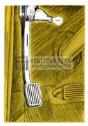
1953 Buick Parking Brake
This is a mechanically operated brake which locks both rear wheels. This brake is operated with the foot and is located on the left side under the instrument panel.
This brake is self-locking and will remain applied until the knob marked “Brake”, located at lower left Range of instrument panel, is pulled out to release. This brake should always be released before the car is driven.
A warning light in the instrument panel lights if the ignition is turned on and the brake is not released. (Standard on Roadmaster, Optional on Series 40 and 50.)
JACK
CHANGING REAR TIRES
1953 Buick Jack
(1) Set parking brake, remove hub cap, and loosen w heel bolts. (2) Place jack under bumper face plate and raise until tire clears ground.
In replacing either front or rear wheels, tighten wheel bolts snugly, lower jack until w heel touches ground, then MAKE CERTAIN THAT ALL BOLTS ARE DRAWN UP TIGHT Bolts must be tightened in criss-cross sequence to prevent wheel run-out.
INSTRUCTIONS TO OPERATE DOUBLE ACTION “V” SECTION CAR JACK. TO RAISE CAR-With trip lever on side of housing in a horizontal position, and a firm grip on the jack handle, press down or lift up slowly the full travel of the handle. As the ratchet or pawl releases from the rack bar, a distinct click can be heard. Continue the up and down movement of jack handle until car is raised to height desired.
TO LOWER CAR-The trip lever should be in the down or vertical position . To lower the car, operate the jack handle the same as for raising the car.
INSTRUCTIONS TO OPERATE SINGLE ACTION RECTANGULAR SECTION JACK.
With the trip lever in the horizontal position, the jack will raise the car with a downward movement of jack handle. There is no load on the jack handle during the upward movement of handle.
CHANGING FRONT TIRES
1953 Buick Tire Changing
(1) Set parking brake and remove hub cap with sharp end o f jack handle. (2) S lightly loosen all wheels bolts. (3) Place jack under front bumper jus t outside of bumper bomb and raise jack until tire clears ground.
If car is equipped with w ire w heel covers, First remove hub cap at center of cover revealing wheel lugs . Note that three lugs al so hold wire wheel cover. After replacing w heel, install cover as shown.
1953 Buick Wheel Covers
HOOD OPERATION
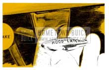
1953 Buick Hood Latch
The Buick hood is a conventional front opening, spring counterbalanced hood, of the so-called “alligator” type.
The hood latch is controlled from inside the car by the ‘T ‘ shaped knob mounted on the lower Range of the instrument panel to the left of the steering column. To open hood, pull out firmly on the latch control knob. This will release the lock and allow the hood nose to raise slightly, providing an opening
between the radiator grille frame and the lower edge of the hood nose for access to the “safety-latch”. This latch is located at the center of and just inside of the lower edge of the hood nose. Releasing this latch will permit the hood to be raised to the open position; it being held in this position by the hinge springs.
To close the hood, lower and push the front end firmly downward to re-engage the lock. Make sure the hood is closed with sufficient force to securely engage the lock. If not properly locked, the hood will remain slightly open and be secured only by the safety-latch.
DIRECTION SIGNALS
To operate the turn signals, the ignition switch must first be turned on. The switch lever on the left of the steering column should then be pushed up for a right turn and down for a left turn. This action causes the front lamp and the lower of the two lamps mounted at the extremity of the rear fender, to flash on that side of the car in which direction the turn is to be made.
Verification of the proper functioning of both front and rear lamps is indicated by a flashing of one of the illuminated green arrows, located in the gauges to the right and left of the speedometer on Series 50 and 70 cars and to the right or left of the light indicator emblem, located between the two instruments on Series 40 cars.
If the arrow does not light and Rash, after movement of the turn signal lever, it indicates that the signal system is not functioning properly and should be checked for burned out bulbs in either front or rear signal lamps or the bulb which illuminates the green arrows.
Always INDICATE a turn at a reasonable distance before making the turn.
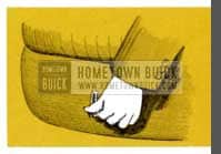
REAR COMPARTMENT
1953 Buick Trunk Handle
The compartment lid lock is located directly below the rear compartment ornament. Insert and turn the key and raise the comportment lid, using lower edge of ornament as a handle. To lock, firmly close lid.
BUICK RADIOS
SONOMATIC RADIO
1953 Buick Sonomatic Radio
Switch and Volume Control (left Knob) – The first portion of rotation in a clockwise direction turns on the radio. Further rotation increases volume.
Tone Control (Chrome Plated Lever Behind the Volume Control Knob) – Control in extreme “treble” position gives brilliant reproduction of the full tone range. This position will reproduce speech very clearly and distinctly. Rotation counterclockwise (toward “bass”) diminishes brilliance and accentuates low notes.
Tuning Control (Right Knob) – When tuning manually, or when setting up a station on one of the buttons, remember-If the program sounds shrill or distorted, it is probably caused by improper tuning and can be corrected by adjusting the tuning knob slightly. Since the low notes are more affected by tuning than the high tones, it is a good plan to tune the set to a point where the low notes are heard best and the high notes are clear but not shrill.
PUSH BUTION SET-UP – Setting the push buttons to tune to any desired station is a simple procedure requiring no tools or equipment.
Procedure is as follows:
- Turn on radio.
- Press button to left and at the same time pull it out as far as possible.
- With button out, tune in the desired station manually. (Do this very carefully as the push buttons will automatically repeat the tuning each time they are pushed. If incorrectly tuned when set-up they will always be incorrect until setting is changed manually.)
- Push button in as far as possible. This automatically completes the button set-up and locks the mechanism in position.
SELECTRONIC RADIO
1953 Buick Selectronic Radio
Buick’s Selectronic Radio is an innovation in radio tuning and provides a simple method of station selectivity regardless of locality. Unlike the Sonomatic Buick Radio which automatically tunes known stations in a particular locality, the Selectronic set automatically and quickly tunes in stations all along the dial which fall within the signal strength set by the operator.
Signal strength selectivity may be set at any one of four positions by turning the sensitivity knob located behind the manual tuning knob to either “MORE” or “LESS”. Extreme movement of the knob toward “MORE” will include all available stations. By turning the knob to the extreme “LESS” position, nearly all stations are eliminated except strong local stations. Antenna should be “up” and fully extended.
After setting the sensitivity control knob at any one of the four positions, turn on the set and move the dial indicator by either pressing the foot switch or the selector bar on the front of the set. Touch either momentarily and the dial indicator will automatically move to the next station on the dial having sufficient signal strength to fall within the range for which the sensitivity control is set. By repeating this operation intermittently, the dial indicator will “search” the entire width of the dial and automatically return to the low frequency end of the dial ready to “search” the entire dial again.
Volume is controlled by the knob at the left end of the dial. By simply turning the knob clockwise, volume may be increased. Varying degrees of tone between treble and bass are obtained by turning the knob behind the volume control knob as indicated.
In some cases, when it is desirable to tune the set manually, simply operate the manual tuning knob at the right of the dial as with any conventional radio.
ANTENNA (Both Radios)-This is swiveled and can be swung “up” or “down” by means of a knob located inside of car just above windshield at center.
For satisfactory operation of the Selectronic Radio the antenna should be in “up” position and fully extended.
ELECTRIC CLOCK
1953 Buick Clock
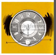
To reset clock, puII knob “A” at bottom of clock out and turn in desired direction.
To regulate the clock for more accurate timekeeping, place small screwdriver or similar tool in slot in small knob “B ” behind the reset knob and turn toward “F” if clock is running slow, or toward “S” if clock is running fast. It is advisable to move the regulator only one division or graduation at a time. By following this procedure your clock may be regulated to keep exceptionally close time.
FAILURE OF CLOCK TO RUN-IMPORTANT – The Electric Clock requires special attention when reconnecting a battery that has been disconnected for any reason, a clock that has been disconnected, or when replacing a blown fuse. IT IS VERY IMPORTANT THAT THE INITIAL WIND BE FULLY MADE.
To be certain of this proceed as follows:
(1) Make sure that all other instruments are off.
(2) Connect one terminal of the battery first. Before permanently connecting the other cable, touch the terminal to its post on the battery. Immediately afterward strike the terminal again to see if there is a spark. If there is, allow the clock to run down until it slops ticking and repeal as above until there is no spark. Then immediately make the permanent connection before the clock can again run down. The clock will run down in approximately 2 minutes.
The above procedure should also be followed when reconnecting the clock after connections have been removed, or when replacing a blown fuse. Be sure to disconnect the battery cable before installing new fuse.
Failure of clock to run may be caused by any of the following:
Blown fuse -discharged battery-corroded battery terminals -wire improperly connected to light switch, fuse block or terminal connection to back of clock – or defective clock.
In replacing fuse, use only 3-ampere AGA fuse on Series 40 and 2- ampere AGA fuse on Series 50 and 70.
TIRES
For maximum tire service-keep tires properly inflated – use an accurate gauge – after inflating, be sure valve caps are in place and screwed down finger-tight.
EXTRA LOW PRESSURE TIRES
Use air pressure as indicated below for checking proper inflation.
1953 Buick Tire Over Inflation
1953 Buick Tire Under Inflation
1953 Buick Tire Proper Inflation
24 Lbs. (starting pressure) AFTER the car has been standing for three hours or driven less than a mile.
In temperatures below freezing, inflate 2 lbs. higher.
26 Lbs. (city pressure) AFTER driving the car three miles or more BELOW 40 miles per hour.
28 Lbs. (highway pressure) AFTER driving the car three miles or more ABOVE 40 miles per hour.
It is normal for air pressure t o build up in a tire due to driving conditions.
DO NOT LET AIR OUT OF TIRES TO REDUCE THIS INCREASE IN PRESSURE
EQUALIZE WEAR ON TIRES
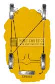
1953 Buick Tire Wear
CHANGE TIRES TO POSITIONS SHOWN IN DIAGRAM AT LEFT AT LEAST EVERY 4000 MILES.
This change of position helps out uneven wear on front tires and distributes the faster wear on the rear tires over all five tires.
CLEANING WHITE SIDEWALLS
Use soap, warm water, and stiff brush to remove road grime and curb dirt from white sidewall tires.
Use medium or fine steel wool for severe cases.
Do not use gasoline, kerosene, or any oil product that will discolor the sidewalls and rot the rubber.
By comparing air pressure in all tires, any variation in pressures will be evident.
To prevent flat tires, investigate and correct a continued loss of air in any tire.
CONVERTIBLE COUPE
The power operating switch for raising or lowering top is located on lower Flange of instrument panel at right of steering column.
TO LOWER TOP
1953 Buick Convertible Top Release
- Stop car.
- Release catch above windshield.
CAUTION: Before operating power top control button make certain that the top directly above the windshield is raised slightly in order- to clear windshield dowels. Close catch.
- With ignition switch on, pull control knob away from panel and hold until top is completely lowered.
- After top is lowered, raise it slightly by hand and pull the top material and padding out from under the roof bow so that it lays in position shown.
1953 Buick Convertible Top Cover
1953 Buick Raise Convertible Top
TO RAISE TOP
- Stop car.
- Remove top boot and unfasten hold down strap.
- Push t op control knob forward and hold until top is full y raised.
- Draw t op down over windshield header dowels and fasten catch to lock top.
To keep mechanism in good condition the top should be operated at least once a month. CAUTION: DO NOT OPERATE EITHER UP OR DOWN WHILE CAR IS IN MOTION.
If top is to be left folded for any length of time it should be securely strapped down to prevent chafing of top material. Also, boot should be installed to keep top clean and dry.
Wiring for power-operated top, side windows and front seat is protected by a 30 ampere circuit breaker having automatic reset.
CARE OF CONVERTIBLE MODEL TOPS – The ONLY METHOD RECOM MENDED for cleaning convertible top material is the use of lukewarm (not hot) water, and a mild (not caustic) soap. The top should be cleaned carefully from end to end using a medium stiff brush or sponge. Do not saturate at any point. Do not fold top when wet. Frequent brushing with an ordinary upholstery brush or stiff whisk broom is helpful in preventing dust and dirt from imbedding itself in the fabric.
CARE OF PLASTIC BACK WINDOW – To avoid scratches to which the back window is susceptible, use only a soft cotton cloth moistened with tepid (not hot) water and mild (not caustic) soap. Rinse with clear water and dry with a slightly moistened soft, clean cloth. NO OTHER CLEANING METHOD IS RECOMMENDED.
POWER OPERATED WINDOWS AND FRONT SEAT
1953 Buick Power Windows
Each panel is equipped with an operating button which is pushed down to lower the window, and pushed up to raise the window.
Power for windows and seat is obtained from the same unit used to operate the power top.
ESTATE WAGON
CARE OF FINISH
Sand and varnish all wood parts once a year. Dulux No. RA-190 is recommended. Sand, fill, and varnish (3 coats) all wood joints as needed. Wax wood parts every 90 days. Before refinishing, remove dirt and wax with clear gasoline.
FOLDING REAR SEAT
Adjust front seat forward and open each rear door before folding rear seat cushion and back. This will prevent scuffing the seat back.
ENGINE AND SERIAL NUMBERS
There are two numbers which identify your car. They are recorded by the license bureau of the state in which your car is licensed. See accompanying illustrations showing locations of these numbers.
ENGINE NUMBER – On the Series 40, the engine number is stamped on a boss on the right hand side of the crankcase below the push rod cover and between the distributor and ignition coil. On the Series 50 and 70 engine, the engine number is stamped on the outside of the left bank of cylinders on an extension of the top face of the block, halfway back.
1953 Buick Engine Number Location – Series 40
1953 Buick Engine Number Location – Series 50-70
SERIAL NUMBER – Plate is affixed to left front windshield pillar post and is visible by opening the left front door.
1953 Buick Serial Number Location
BATTERY
1953 Buick Battery
CUATION – Electric Storage Batteries give off highly inflammable hydrogen gas when charging and continue to do so for some time after receiving a steady charge.
Under no condition should an electric spark or an open Rome be allowed near the battery, particularly in the vicinity of the vent caps.
Before doing any work around a battery a metallic contact between the car bumper and the ground should be made to remove the possibility of a static charge causing a spark in the vicinity of the battery. A long metal bar or a metal chain of sufficient length will accomplish this.
COOLING SYSTEM
1953 Buick Radiator
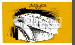
The Buick cooling system is a sealed pressure type which raises the coolant boiling point. There is no need to check coolant level as long as the operating temperature remains normal. Never check level until the engine has been stopped for several minutes. When checking level, always remove cap slowly to be sure the engine has cooled enough to remove the pressure even at normal temperatures.
The system should be drained twice a year. It is important that a rust preventive be added when refilling. Proper coolant level is stamped on the engine side of the radiator as shown -DO NOT FILL ABOVE THIS LINE.
CAUTION – When installing anti-freeze, do not use solutions that contain salt, oils, kerosene, sugar, glucose or honey.
CLUTCH ADJUSTMENT
(Synchro-Mesh Transmission)
There should be 3/4 of an inch to 1 inch “lash” or free movement in the clutch pedal at all times.
Unless some “lash” is maintained the clutch may slip, necessitating replacement of clutch parts due to excessive heat and wear.
CARE OF CHROME AND FINISH
The new type chrome on your car will retain its beauty and brightness providing special precautions are taken in its care. In cleaning, use only clean water frequently. DO NOT USE SCOURING POWDERS OR CLEANING COMPOUNDS. After cleaning, apply Buick Chrome Preservative at approximately four-week intervals. It is available from your Buick Dealer and provides excellent protection against dampness, chlorides, and corrosion.
MAP LAMP BULB REPLACEMENT
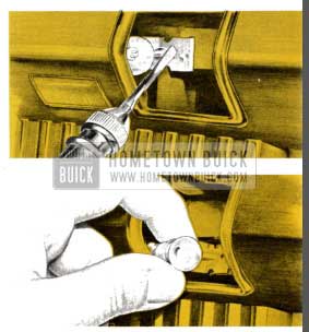
1953 Buick Map Lamp Bulb Replacement
- Remove ash tray adjacent to map light having burned out bulb.
- The bulb, socket and clip assembly is now visible behind the map light glass.
- Insert screwdriver in slot and pry bulb, socket and clip assembly from re-enforcing plate.
- Socket may now be held in hand while replacing bulb.
- Socket may be reinstalled by pressing clip on the re-enforcing plate making certain clip is in depressed area.
SPEEDOMETER TRIP MILEAGE
1953 Buick Speedometer Trip Mileage
The Buick speedometer is equipped with a reset knob so that the lower mileage dial can be set to zero at the start of a trip. To reset to zero merely push in knob and turn in clockwise direction until all digits read zero. To adjust forward, push in knob and turn in counter clockwise direction. This sets reading forward by tenths of a mile.
LAMP BULBS
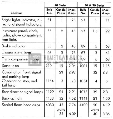
1953 Buick Lamp Bulbs
| Location | 40 Series | 50 & 70 Series | ||||
| BulbNo. | CandlePower | Max . Amps. | BulbNo. | CandlePower | Max. Amps. | |
| Bright lights indicator, di- rectional signal indicators . | 51 | 1 | .25 | 53 | 1 | .11 |
| Instrument panel, clock, radio, glove compartment, map light. | 55 | 2 | .45 | 57 |
|
.22 |
| Brake indicator | 55 | 2 | . 45 | 89 | 6 | .63 |
| License plate lamp | 63 | 3 | .73 | 67 | 3 | .41 |
| Trunk compartment lamp | 81 | 6 | 1.14 | 89 | 6 | .63 |
| Dome lamp | 210 | 15 | 2.04 | 1004 | 15 | 1.15 |
| Combination front, signal and parking lamp Combination stop, and tail lamp | 1154 | 213 | 2.97. 73 | 1034 | 324 | 2.3.5 |
| Rear direction signal lamps | 1129 | 21 | 2.91 | 1073 | 32 |
|
| Back-up light | 1133 | 32 | 4.52 | 1141 | 21 | 1.50 |
| Sealed Beam headlamps | 4030 | 45watts35 | 7.746.02 | 4400 | 50watts40 | 4.193.35 |
FREE WHEELING DOOR LOCKS
The rear door locks on f our door sedans are designed and are set so that the inside handles “free-wheel ” when the locking button is pushed down into lock position. This prevents children from accidentally opening the rear doors. The feature can be changed by any Buick Dealer if it is not desired.
When lock is se t for free- wheeling it is necessary to raise the lock button before either the inside or outside handles will open the door.
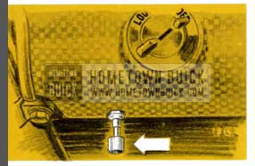
FUSES
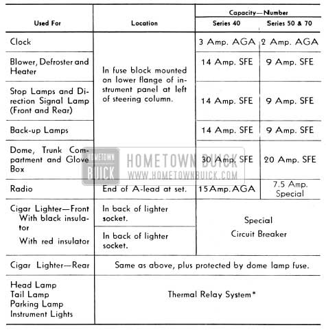
1953 Buick Fuses
* THERMAL RELAY – There are no fuses in the headlamp, tail lamp, parking lamp or instrument lamp circuits.
Protection for these circuits is through a thermostatically controlled current limit relay attached to light switch. When the current load is too heavy, due to a short circuit, the relay opens and closes rapidly thus reducing current sufficiently to protect the wiring from damage. This action continues until the cause is eliminated.
SPECIFICATIONS AND DATA
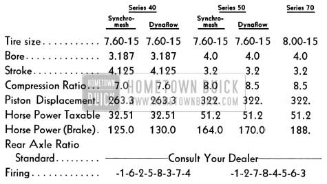
1953 Buick Specifications and Data
CAPACITIES
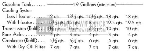
1953 Buick Capacities
ADJUSTMENTS
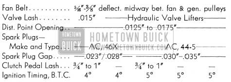
1953 Buick Adjustment
GENERAL MAINTENANCE
Engine – For instructions on maintaining proper oil level see page 4. The crankcase should be completely drained and refilled with new Service M.S. oil of the proper viscosity(SAE grade as shown on table below) at the end of the first 1,000 miles and every 2,000 to 3,000 miles thereafter. Certain types of operation, however, such as short run low speed operation in cold weather or in Metropolitan areas where the car isn’t driven more than 10 or 20 miles a day call for more frequent changing. Also, it is desirable to change the oil more often if the car is operated in extremely dusty territories or driven most of the time on gravel roads. If there is any question about the change interval best suited for your type of driving please consult your Buick Dealer. The oil filter element should be changed at the end of the first 1,000 miles.
TEMPERATURE- SAE GRADE
Not lower than 32°F – 20-W
Not lower than minus 1°F – 10-W
Below minus 10°F – 5-W
NOTE: The use of SAE 5-W oils are recommended during low temperature periods because of their easy starting and quick Row characteristics. SAE 5-W oils marked for “Service MS” or “Service MM” may be used during warm days occurring in the winter season.
EVERY 1000 MILES
Chassis – Wipe dirt from lubrication fittings, then apply a good grade of water-resistant chassis lubricant, under pressure, at the following points: (1) Lower Control Arms, inner and outer ends, (2) Upper Control Arms, (3) Steering Knuckles, (4) Tie Rods, inner and outer ends, (5) Transmission Shift Idler Lever Pin, (6) Clutch Release Equalizer, (7) Clutch and Brake Pedals may be lubricated with engine oil.
Synchromesh Transmission and Rear Axle – Check level at filler plug. Maintain level using SAE 90 Multi-Purpose Gear Lubricant (U. S. Army Spec. 2-105B) for temperatures not lower than 10°F below zero. In temperatures continuously below – 10°F, use SAE 80. Seasonal or periodic draining and flushing is not required. When complete refilling is required, however, use above lubricant in transmission but use only Factory Hypoid Lubricant in rear axle.
Dynaflow Drive – Apply Lubriplate or Chassis Lubricant to notches of control detent at base of steering column for Series 40. Check Trans mission oil level, with transmission oil warm, transmission in Parking and engine idling. If level is more than one inch below “FULL” mark on gauge rod, add oil but do not fill above the “FULL” mark. Distance between “FULL” and “ADD OIL” marks on rod represents one pint. Use oil specified under “Every 25,000 Miles.”
Steering Gear – Check level at filler plug. Maintain level using Multi-Purpose Gear Lubricant as recommended for rear axle. Do not use pressure when filling. Seasonal or periodic change of lubricant is unnecessary.
Cranking Motor (Starter) – Apply a few drops of engine oil to the link pins and fulcrum stud of shift yoke.
Distributor – Force lubricant through fitting on housing until it emerges from relief hole in front of distributor housing in a continuous unbroken stream on the Series 40. Fill oil cup with SAE #10W on Series 50 and 70.
Battery – Add distilled water to bring level to ledge at bottom of slot in well. WARNING: DO NOT FILL ABOVE LEDGE.
Air Cleaner – Normally serviced every 5000 miles. If car is operating in dusty territory, however, check condition of air cleaner and clean it if dirty. See cleaning and filling instructions under “Every 5000 Miles.”
Radiator – Check coolant level only when radiator is cold. Maintain level at line on rear side of head tank marked, “Filling Level -Cold,” using water. Filling above level line or when radiator is hot will cause loss of coolant. CAUTION: Do not remove cap when radiator is hot because coolant will boil and overflow when pressure is released. When refilling cooling system after draining, “Heat Control ” lever at bottom center of radio grille must be pushed to left to high position. See Page 4.
NOTE: If cooling system is being drained for storage where freezing is likely to occur, it is necessary to disconnect heater and defroster hoses to thoroughly drain them. If car is Dynaflow equipped, disconnect lower hose at transmission oil cooler.
Manifold Valve Shaft – Place a few drops of graphited kerosene on shaft at each end and rotate shaft to work lubricant into bearings. If shaft is frozen, free up by tapping ends of shaft lightly with hammer .
Throttle Control Linkage – Place a few drops of engine oil at connections. Work Lubriplate into Equalizer Shaft bearings and wipe off surplus lubricant.
Generator – Place a few drops of engine oil in cups at both ends of generator. Avoid excessive oiling which may affect brushes and windings. Do not lubricate while generator is in operation.
Master Brake Cylinder -Thoroughly clean filler cap nut before removal to avoid getting dirt into reservoir. Add fluid as required to bring level to 1/2″ to 1″ below top of filler opening. Use G.M. or Delco Super No. 11 Hydraulic Brake Fluid. NEVER USE RECLAIMED FLUID OR ANY MINERAL OIL.
Tires-Inflate all tires to pressures given on page 15.
WARNING: It is not possible to in Rate tires correctly when they are hot.
Hood Fastener Mechanism – Lightly coat latch lever and pilot with Lubriplate.
Door Locks and Strikers – Use only SAE 10 engine oil at following points (1) Between roller and bolt (2) Edges of bolt slot in door (3) Bottom surfaces of upper and lower guide channels in striker (4) Lower surface of wedge plate bumper. Apply light lm and wipe off surplus oil. Apply solution type graphite lubricant where bumper bears against striker plate.
Door Checks and Hinges – On Series 40, apply Lubriplate or chassis lubricant to hold-open springs in front door hinges. Use same lubricant sparingly on lugs of all rear door check links. On Series 50-70 apply light engine oil to check link pins. No lubricant required on hinge pins.
Dome Lamp Door Switches – Apply G. M. Door-Ease Lubricant to end of switch plunger and point of contact on door hinge pillar.
Glove Box Door – Apply a few drops of light engine oil to glove box door hinges -wipe off surplus oil. Sparingly coat lock striker with G. M. Door-Ease Lubricant.
Windshield Wiper Cables on Series 50 and 70 Cars – Wipe a few drops of light engine oil on cables where they pass over tensioner pulleys. CAUTION: WINDSHIELD WIPER BLADES MUST NOT BE ROTATED BY HAND FOR ANY REASON AS THIS PLACES AN UNDUE STRAIN ON CABLE FASTENINGS.
Gas Tank Filler Door – Apply a few drops o f light engine or penetrating oil on the hinge pins. Wipe off excess to prevent accumulation o f fine dust and dirt.
Rear Compartment Lid Lock – Lightly coat lock latch and lock striker with Lubriplate.
Lock Cylinders – If key operates roughly in lock cylinder, blow powdered graphite into key slot. DO NOT USE OIL.
FIRST 2000 MILES
Lights – Check all lights and aiming of headlamps.
EVERY 5000 MILES
Distributor – Remove distributor cap and rotor. Apply a few drops of light engine oil to felt wick in top of cam. Put 1 drop of oil on breaker arm pivot. Work a small amount of M-1172 ball bearing grease into a cloth, then hold cloth on distributor cam while engine is being cranked. CAUTION: AN EXCESSIVE AMOUNT OF GREASE WILL THROW OFF WHEN HOT AND INSULATE THE CONTACT POINTS, CAUSING IGNITION FAILURE.
Power Steering Gear – All models use a pump having an integral reservoir. To check oil level, remove cover from top of reservoir and see if oil comes to specified level. Add oil specified for Dynaflow Drive to maintain level.
Air Cleaner -Every 5000 miles (more often under dusty operating conditions) disassemble air cleaner and wash cleaner element and oil sump with a non-inflammable solvent (kerosene is not recommended). Wipe sump dry and allow cleaner element to drain until dry. DO NOT USE AIR BLAST ON CLEANER ELEMENT. Fill sump to indicated level with one pint SAE 50 engine oil and assemble air cleaner. DO NOT OIL THE CLEANER ELEMENT BECAUSE OIL WILL DRAIN BACK INTO THE SUMP AND CAUSE SUMP TO BE OVERFULL.
Oil filter – Change oil Filter element at First 1000 miles, then 5000 miles and each 5000 miles thereafter* Remove old element, remove drain plug, and wipe container out thoroughly with CLEAN cloths. Install drain plug, new element, and new cover gasket. Use only Buick Oil Filter Replacement Element Part No. 5572129 (AC P127) on Series 40 and Part No 55 72128 (AC PF-122) on Series 50 and 70, or equivalents.
*In extremely dusty areas, more frequent change may be desirable.
Pump Operating Countershaft – Carter Carburetor Only -Remove the two dust cover attaching screws and apply several drops of engine oil in screw holes above countershaft. Install screws.
Horn Cable Connector – Pull out plunger and apply a small amount of Lubriplate. Work plunger in and out.
Lights – Check all lights and aiming of headlamps.
EVERY 10,000 MILES
Front Wheel Bearings – Wipe old grease out of hub and wash bearings. Work approximately one tablespoon of wheel bearing lubricant into each ball bearing. The oil seal packings should be examined for wear or leaking and replaced if necessary.
Bearing Adjustment – Take up spindle nut with 10″ wrench until bearings are preloaded at least 1 hex, then rotate wheel1 revolution to make sure bearings are seated. Back off spindle nut until bearings are loose. Tighten nut until all bearing looseness is just removed, then line up nut to nearest cotter hole and install cotter pin. Do not mistake loose king pin bushing, etc., for wheel bearing looseness. CAUTION: BEARING PRELOAD MUST NOT EXCEED 1/12 TURN OF NUT.
Shock Absorbers – Inspect and fill to proper level using only Delco Shock Absorber fluid. For filling instructions consult Authorized Buick Dealer.
EVERY 25,000 MILES
Dynaflow Transmission – At 25,000 mile intervals the oil pan and torque converter should be completely drained and re-filled with fresh oil. Transmission MUST NOT BE FLUSHED when oil is changed. Use Special Buick Oil for Dynaflow Drive or any Automatic Transmission Fluid, Type A, which has an AO-ATF identification number embossed in lid of container.
Put in 3 quarts of specified oil. With engine idling in Parking, complete the refilling to bring oil level to 1 3/4″ below “FULL” mark on gauge rod. When transmission oil is warmed up, the oil level should then be at “FULL” mark on gauge rod.
ONCE A YEAR
Hydro-Lectric System – Each Fall all windows should be lowered, the seat moved back and the reservoir on the power unit removed, cleaned out with Declene or alcohol and then refilled with G.M. or Delco Super No. 11 Brake Fluid. Brake fluid heavier than No. 11 should not be used in extremely cold climates as it will cause sluggish operation of the Hydro-Lectric system.
CAUTION: Before installing reservoir, make certain that reservoir gasket is in good condition and properly install ed. When reservoir is installed make certain that it makes full contact with gasket all around. Any leakage of dirt or water into reservoir will cause serious damage in Hydro-Lectric system.
Each Spring the folding t op power cylinder piston rods should be lubricated with a few drops of castor oil or brake fluid. DO NOT USE MINERAL OIL.
AS REQUIRED
Rear Wheel Bearings – Rear wheel bearings need not be lubricated more often than 20,000 m iles. Whenever rear brakes are relined, or a x le shafts are removed for other work it is advisable to inspect rear wheel bearings and oil seals. Replace seals if leaking or worn. Fill rear wheel bearings and space between oil seals with wheel bearing lubricant. Coat leather edges of seals with lubricant before installation of axle shaft.
Speedometer Cable – The speedometer cable is factory lubricated with special grease and normally requires no further service unless it becomes noisy. In extremely hot climates, or where considerable dust and water is encountered it may be necessary to lubricate the cable at intervals of approximately 20,000 miles or every two years. It is advisable to have this service performed by an Authorized Buick Dealer to insure use of the special grease in proper quantity.
Sunshade – If sunshade rod turns hard in support, remove retainer screw, pull rod from support and apply G. M. Door-Ease Lubricant. Do not use oil which may soil trim. Install rod in support and adjust retainer screw to proper tension.
Cleaning Leather – (1) Apply a damp (not wet) cloth to mild soap and rub surface of leather briskly. (2) Wipe with moist cloth without soap. (3) Rub dry with clean, soft cloth.
MODELS, WHEELBASES AND LENGTHS
SPECIAL SERIES 40
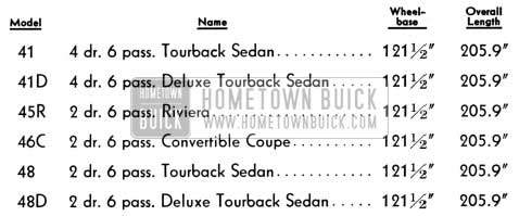
1953 Buick Special Series Wheelbase and Length
SUPER SERIES 50
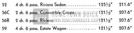
1953 Buick Super Series Wheelbase and Length
ROADMASTER SERIES 70
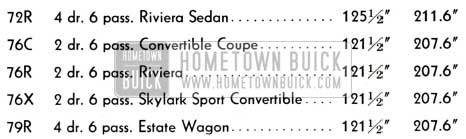
1953 Buick Roadmaster Series Wheelbase and Length
License Weight: Consult the Dealer who sold you the car, or the Motor Vehicle Commissioner of your State. Weights of all Buick body styles are regularly supplied to these authorities.
Leave A Comment
You must be logged in to post a comment.