Project Description
1952 Buick Body Changes
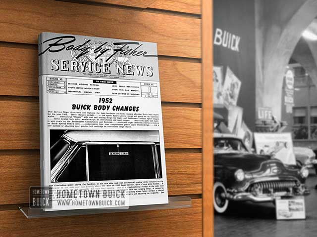
1952 BUICK BODY CHANGES
This Service News illustrates and explains the body hardware and trim changes affecting 1952 Buick Body Changes. These changes include… a low speed Hydro-Lectric motor and pump for all hydraulic styles… mechanical “flipper” side roof rail sealing strips for Super and Roadmaster Riviera Sport Coupes… newly located lock pillar weatherstrips on convertibles and sport coupes… door trim pads with built-in arm rests on the Roadmaster Convertibles and Rivieras… windshield wiper torsional inertia arresters on Buick Special bodies only… compression type rear compartment gutter upper weatherstrips.. . .. and a new method of attaching rear quarter belt moldings on convertible coupe styles.
1952 Buick Side Roof Rail Mechanical Sealing Strip
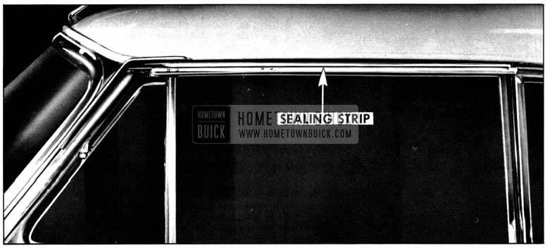
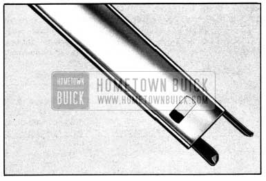
The illustration above shows the location of the new side roof rail mechanical sealing strip installed on the underside of the side roof rail directly above the door on 1952 Super Riviera Sport Coupe style bodies. It comes in a right and left assembly for each door opening. Due to a constructional change in the side roof rail on 1952 Super and Roadmaster Riviera Sport Coupes to accommodate this new sealing strip, it cannot be used on previous 1950-51 Riviera Sport Coupe style bodies. Slotted attaching screw holes permit a lateral or in and out adjustment which is attained by loosening the attaching screws and adjusting as required. See adjustments on page 4.
SIDE ROOF RAIL MECHANICAL SEALING STRIP
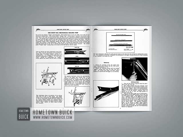
One of the new changes on Super and Roadmaster 56R and 76R styles for the year 1952 is the side roof rail mechanical sealing strip. This chrome plated “Flipper Type” sealing strip is attached with screws to the lower face of the side roof rail directly above the doors so as to provide an adequate weatherseal at this area. The sealing strip is designed with a spring tensioned outer hinged section which is actuated mechanically by contact with the upper section of the door ventilator frame when the door is opened and closed. When the door is closed, the hinged outer section of the sealing strip under spring tension, flips downward to form a conventional channel which compresses against the chrome channel along the top of the door ventilator and window thus forming a tight weatherseal. When the door is opened the hinged outer section of the sealing strip flips upward out of the way to provide door glass and door ventilator frame clearance. The chrome plated “Flipper Type” sealing strip is not used on the 1952 Special Riviera bodies.
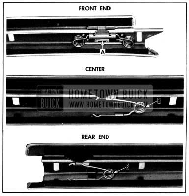
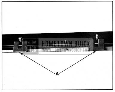
Close-up showing the inner construction of the front end, center and rear end portion of the mechanical sealing strip with hinged “flipper” section in a raised position. “A” indicates the striker plate and spring for operating the “flipper, ” “B” the “over center” springs for compressing the “flipper” section against the window when the door is closed.
1952 Buick Front End Inner Constuction
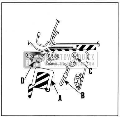
The opposite illustration shows the operating principle of the flipper type sealing strip. In the process of closing the door, the top of the door ventilator frame “A” engages against the striker on the sealing strip indicated at “B” which actuates tension spring “C” in the channel and causes the hinged section “D” of the sealing strip to “flip” downward to form a compression type channel as shown in the next illustration.
1952 Buick Flipper Type Sealing Strip
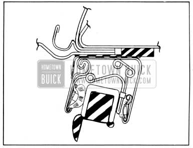
This illustration shows the position of the sealing strip when the door is fully closed. The hinged section of the sealing strip has flipped downward and is held by compression against the outer surface of the chrome window channel and ventilator frame. When the door is opened, the hinged section by spring tension “flips” upward as shown above to allow door clearance.
1952 Buick Sealing Strip
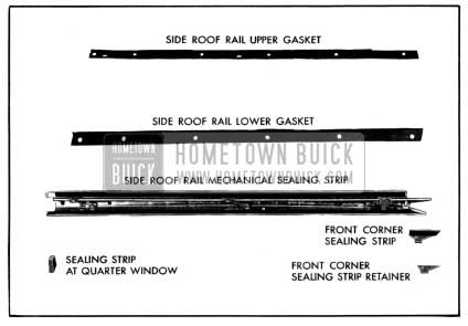
1952 Buick Side Roof Rail Mechanical Sealing Strip Assembly
The above illustration indicates the parts and part names of the side roof rail mechanical sealing strip assembly. For installation to the 1952 Buick body, the gaskets are assembled to the flipper sealing strip and the whole assembly is then installed to the body as a unit.
REMOVAL
1952 Buick Side Roof Rail Mechanical Sealing Strip Gasket
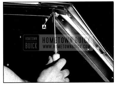
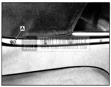
- Remove the attaching screw, the small front corner sealing strip retainer and the front corner sealing strip indicated at “A”.
- Remove the attaching screws and the chrome “flipper” sealing strip from the side roof rail. NOTE: The sealing strip upper and lower rubber gaskets are removed with the flipper as an assembly.
INSTALLATION
1952 Buick Side Roof Rail Mechanical Sealing Strip Installation
- Clean off old sealing compound from the underside of the side roof rail.
- After rubber gaskets have been removed, clean off the top surface of the mechanical sealing strip, then tape the “flipper” down in the closed position. Apply a light uniform coating of 3-M Weatherstrip Adhesive to the top surface. Adhesive must be applied so as not to enter the hinge portion or attaching screw holes.
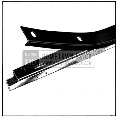
- Clean off and apply a light coat of 3-M Weatherstrip Adhesive to the bottom surface of the side roof rail lower rubber gasket. This gasket has a molded “lip.” Adhesive must not be applied to this lip. Cement the rubber gasket to the top surface of the sealing strip so the lip of the gasket is precisely located over the outside radius of the hinge through.:. out its entire length. See opposite illustration. NOTE: At the factory, a double coated adhesive tape is used to cement the lower rubber gasket to the top of the sealing strip. For service installation however, discard the tape and use 3-M Weatherstrip Adhesive as explained.
1952 Buick Upper Rubber Gasket
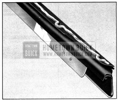
- Using 3-M Weatherstrip Adhesive, cement the upper rubber gasket to the top surface of the already installed lower gasket.
- Next, holding the assembly, apply a uniform continuous 1/8″ ribbon of 3-M Caulking Compound along the top surface (center line) of the upper gasket on the sealing strip as illustrated.
- If necessary, recement the small angular rubber weatherstrip to the front end of the sealing strip used above the quarter window.
1952 Buick Side Roof Rail Mechanical Sealing Strip Gasket
- Carefully install the mechanical sealing strip and its gaskets to the underside of the roof rail above the door. Before tightening screws, make sure the channel of the sealing strip aligns properly with the top of the door window and ventilator.
- To complete the installation, cement and reinstall the small front corner rubber sealing strip and its retainer as illustrated opposite at “A”.
SEALING STRIP ADJUSTMENT
1952 Buick Side Roof Rail Mechanical Sealing Strip Adjustment
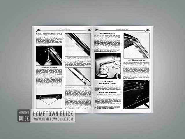
The attaching screw holes in the chrome mechanical sealing strip are slotted laterally to allow in or out adjustment for alignment with the top of the door window and door ventilator. To adjust, simply loosen the attaching screws and move in or out the desired amount, then tighten screws again. VERY IMPORTANT: If the flipper on the sealing strip has a tendency to bind or is slow operating, loosen the attaching screws, one at a time until the screw causing the bind is located and the “flipper” snaps up to its proper tension, then correct and check door clearance as explained below. Do not swage or hammer the sealing strip. Do not pry with a screw driver. Do not tamper with the spring mechanism. Such abuse will damage the mechanism and render it inoperative.
1952 Buick Mechanical Side Roof Rail Sealing Strip
IMPORTANT: The mechanical side roof rail sealing strip must be installed to the underside of the roof rail on a true flat plane so that the “flipper” or hinged portion is free operating. ‘If a “bow” occurs in the long “flipper” hinge after installation, it might result in a binding or slow operating flipper which could become seriously damaged when the door was opened or closed. During installation, all rubber gaskets must be cemented flat without “puckers.” Cement application must be of uniform thickness and attaching screws must be drawn to uniform tightness. To compensate for any slight variation that might cause a binding flipper hinge, slotted shims or spacers can be made from waterproof cardboard as illustrated. After loosening the attaching screws at the “bowed” section, shims can be inserted between the upper gasket and side roof rail so that the slot in the shim straddles the shank of the attaching screw as shown in opposite illustration at “A”.
DOOR RAIN DEFLECTOR
1952 Buick Door Rain Deflector
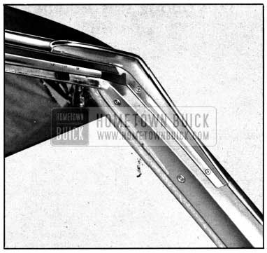
Two types of rain deflectors are used on Buick Riviera sport coupe styles. First run bodies will use the same type rain deflector as used in 1951. The second type rain deflector is a redesign of the first type, to allow clearance for the new mechanical sealing strip. On the Special Series Riviera style body which does not use the side roof rail mechanical sealing strip, both types rain deflector will be used. The only deviation between the two types of rain deflectors is… the first type is attached directly to the side roof rail under the sealing strip and the second type attaches to the underside of the drip molding. The attachment of both types of rain deflectors at the front pillar area is the same. illustration shows second type rain deflector.
REAR COMPARTMENT LID
1952 Buick Rear Compartment Lid
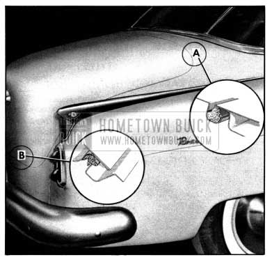
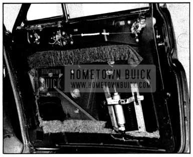
The rear compartment lid has been redesigned on all “45” and “47” series body styles. This change consists of raising the lid top surface to give a new appearance to this area of the 1952 Buick body. Two types of rear compartment rubber weatherstrips are used for sealing the rear compartment lid in the opening. A bulb or compression type weatherstrip is cemented into the gutter at the upper part of the opening, which compresses against the flanges of the lid when closed, see opposite inset “A”. A “lip” type weatherstrip “B” is cemented to the lower and side flanges of the lid which compresses against the gutter of the opening when the lid is closed. The cemented attachment of both rubber weatherstrips is similar to the method used on 1951 models.
DOOR TRIM PAD WITH BUILT IN ARM REST
The door trim pad on Roadmaster Convertibles and also on two and four door Rivieras is of a new design which incorporates a built-in arm rest. The trim pad and arm rest are removed as a unit as follows:
REMOVAL AND INSTALLATION
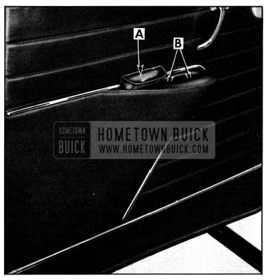
1952 Buick Door Trim Pad
- At the bottom of the arm rest recess, remove the single screw and trim cup “A” as illustrated.
- After trim cup removal, at the bottom of the recess, remove the two retaining screws “B”.
- Remove door window garnish molding, inside handles and Hydro-Lectric switch if equipped. On rear doors of four door Rivieras, remove the wind deflector from the division channel.
- Remove single screw at each lower corner of the pad.
- Carefully disengage attaching nails along sides of the trim pad, lift pad outward and upward to remove.
- To install, reverse this procedure.
FRONT DOOR SIDE MOLDING
ALL STYLES
The door side moldings on all Buick styles are in stalled to the door outer panel with clip and bolt assemblies.
REMOVAL AND INSTALLATION
1952 Buick Front Door Side Molding
- Remove the door inside hardware and trim pad. In addition, on Hydro- Lectric equipped bodies, raise the window and disconnect the wiring at the HydroLectric switch on the trim pad.
- Remove loading hole covers from door inner panel and through loading hole remove four molding retaining nuts and washers from door outer panel.
- Raise the hood of the car and reach down between the fender and the cowl and remove the nut and washer retaining the end of the side molding at the door flange. Then, remove molding from door.
- To install, reverse the above procedure, reseal around perimeter of loading hole opening with 3-M Autobody Sealer. Also reseal attaching bolt holes with 3-M Autobody Sealer.
REAR DOOR SIDE MOLDINGS
ALL “19” STYLES
REMOVAL AND INSTALLATION
1952 Buick Rear Door Side Moldings
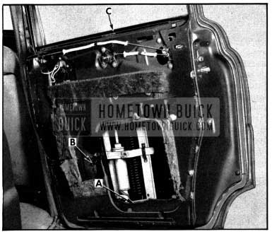
- Remove the rear door inside hardware and trim pad.
- On hydraulically equipped styles, lower the window to a full down position, then disconnect the wiring at the switch.
- Remove the loading hole cover from the door
- On hydraulic styles, disconnect the window lift at “A” and “B”. It is not necessary to break the electrical or hydraulic connections at the lift assembly.
- Grasp the window glass at “C” and raise the entire assembly up and prop it in this position.
- Then, remove six nuts and washers retaining the door side molding through the loading hole.
- Remove molding from door.
- To install, reverse the above procedure. Reseal attaching bolt holes and around the perimeter of the loading hole opening with 3-M Autobody Sealer.
REAR QUARTER SIDE MOLDING
STYLES 4337-4327-4311
REMOVAL AND INSTALLATION
1952 Buick Rear Quarter Side Molding
- Remove rear seat cushion and back.
- Remove rear quarter finishing molding, hardware and trim.
- On “37” styles only, remove loading hole cover.
- Remove nuts and washers from rear quarter molding bolts on inner surface of rear quarter outer panel as indicated by arrows.
- On the outside of 1952 Buick body at lower wheel housing, remove two screws from rear lower flange of molding under rocker panel.
- Carefully remove rear quarter molding.
- To install, reverse the above procedure. Reseal attaching bolt holes and loading hole cover (on Riviera styles) with 3-M Autobody Sealer.
REAR QUARTER SIDE MOLDING
STYLE 4367X (CONVERTIBLE)
REMOVAL AND INSTALLATION
1952 Buick Rear Quarter Side Molding – Covertibles
- Disconnect positive terminal of battery.
- Remove the rear seat cushion and back.
- Remove rear quarter window finishing panel and remove rear quarter arm rest.
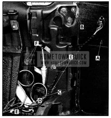
- Loosen rear quarter side trim panel “A” and pivot trim panel out of position. Disconnect hydraulic switch wiring “B” from switch on trim panel.
- Remove the loading hole cover.
- At the window opening, disconnect the rear quarter window cam “C” from the window sash channel and prop window up in a closed position.
- Disconnect quarter window hydraulic lift assembly tubing and wiring “D” (cap end of hydraulic line to prevent leakage of fluid).
- Loosen or remove five bolts “E” attaching quarter window lift to rear quarter inner panel.
- Move quarter window lift out of position, this will give clearance so the molding attaching nuts may be removed from the inner surface of the rear quarter outer panel.
- On the outside of car, remove rear quarter side molding from 1952 Buick body.
- To install, reverse the above procedure. Reseal molding attaching bolt holes and loading hole cover with 3-M Autobody Sealer. Check the hydraulic switch recess in the rear quarter inner panel to make sure insulator is in place.
ROCKER PANEL MOLDING EXTENSION
ALL FOUR DOOR STYLES
REMOVAL AND INSTALLATION
1952 Buick Rocker Panel Molding Extension
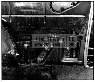
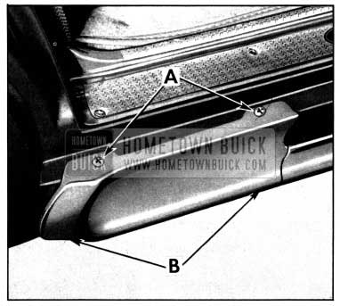
- Open rear door and from top of rocker panel, remove two screws “A”.
- From underneath rocker panel, remove two screws “B” and remove rocker panel molding extension.
- To install, reverse the above procedure. Use 3-M Autobody Sealer to seal around screw holes.
REAR FENDER CROWN MOLDING
SPECIAL “43” STYLES
REMOVAL AND INSTALLATION
1952 Buick Rear Fender Crown Molding
- Raise rear compartment lid and remove rear compartment side trim.
- From inside rear compartment, remove five nuts and washers retaining crown molding “A”. NOTE: On 4367X styles it is necessary to remove two screws from the baffle at the outer quarter and wheelhouse panels to gain access to the front nut.
- To install, reverse the above procedure. On the 4367X style body, reseal the baffle plate and attaching bolt holes with 3-M Autobody Sealer.
REAR QUARTER WINDOW HYDRAULIC LIFT
4367X STYLE
REMOVAL AND INSTALLATION
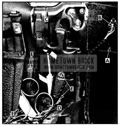
1952 Buick Rear Quarter Window Hydraulic Lift
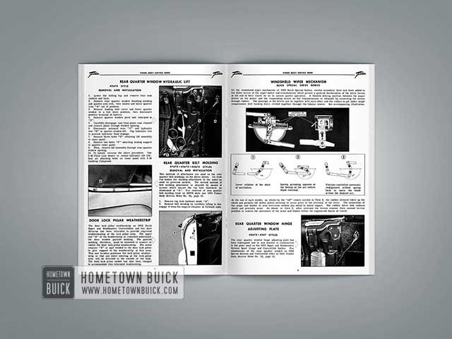
- Lower the folding top and remove rear seat cushion and back.
- Remove rear quarter window finishing molding and quarter arm rest, then loosen and move quarter trim “A” out of position.
- Remove loading hole cover and lower quarter window to a full down position, then disconnect positive terminal of battery.
- Remove quarter window pivot bolt indicated at “B”.
- Carefully disengage cam from glass cam channel and remove glass through window opening.
- Disconnect solenoid wire “C” and hydraulic line “D” at quarter window lift. Cap hydraulic line to prevent hydraulic fluid leakage.
- Remove three bolts “E” retaining lift assembly to inner panel.
- Remove two bolts “F” attaching sliding support to quarter inner panel.
- Then, remove lift assembly through rear quarter window opening.
- To install, reverse the above procedure. Use 3-M Fluid Line Sealer to reseal hydraulic lift line. Seal all attaching bolts on inner panel with 3-M Caulking Compound.
REAR QUARTER BELT MOLDING
4767X-4567X-4367X STYLES
REMOVAL AND INSTALLATION
1952 Buick Rear Quarter Belt Molding
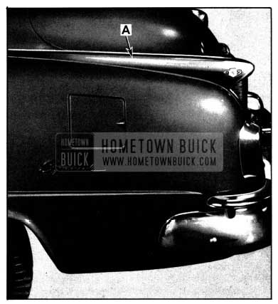
Two methods of attachment are used on the rear quarter belt moldings on the above styles. On first run bodies the molding attachment is the same as used on previous models. The second method of belt molding attachment is attained by means of screws which secure the top boot fasteners as illustrated at “A”. For removal of rear quarter belt molding front on 4367X style see 1951 Fisher Body Service News No. 20, page 16.
- Remove top boot fastener studs “A”.
- Remove belt molding by carefully lifting to disengage it from the snap-on retainer at forward ends.
DOOR LOCK PILLAR WEATHERSTRIP
1952 Buick Door Lock Pillar Weatherstrip
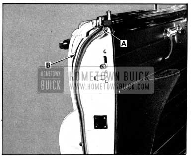
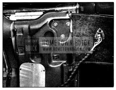
The door lock pillar weatherstrip on 1952 Buick Super and Roadmaster Convertibles and two door Rivieras has been relocated to provide improved weathersealing at the lock pillar area. The upper end “A” of the weatherstrip is cemented underneath the door window garnish molding. The garnish molding, therefore, must be loosened to remove or install the door lock pillar weatherstrip. The metal retainer “B” is spot welded to the door lock pillar to give support to the weatherstrip at this area. This new location positions the lock pillar weather strip so that any water entering at the lock pillar area will be diverted to the outside of the body. The 1952 Buick body lock pillar rabbet has also been changed to accommodate this relocated weatherstrip.
WINDSHIELD WIPER MECHANISM
BUICK SPECIAL SERIES BODIES
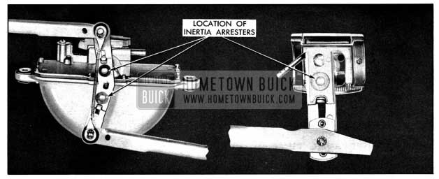
On the windshield wiper mechanism of 1952 Buick Special bodies, inertia arresters have now been added to the drive levers of the wiper motor and transmission which permit a general deceleration of the drive levers at the end of their travel so as to assure quieter operation. A flexible driving junction between the major driver on the motor and the cooperating levers on the transmissions is obtained by connecting the levers through rubber. The openings in the levers are in register with each other and the rubber is put under slight compression with backing discs riveted together through the tubular sleeve. See accompanying illustration.
1952 Buick Windshield Wiper Mechanism
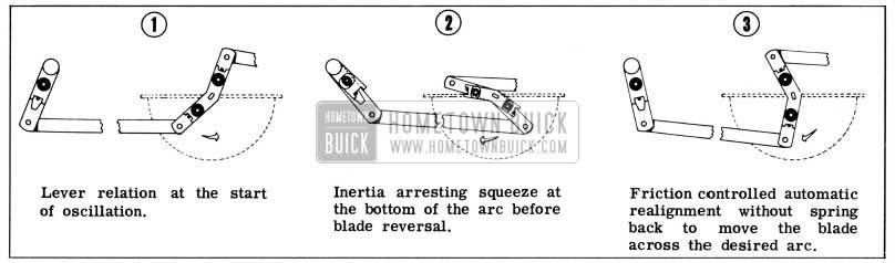
1952 Buick Windshield Wiper Operation
At the end of each stroke, as shown by the “off” center circles in View 2, the rubber element takes up the shock and permits the motor piston reversal to occur prior to the reversal of the lever. The momentum of the arms and blades is also overcome without any metal to metal impact. The rubber drive link reduces shock and prevents noise. As shown in View 3, after reversal the levers resume their normal in-line position to control the movement of the arms and blades within the engineered limits of travel.
REAR QUARTER WINDOW HINGE ADJUSTING PLATE
4367X-4337 STYLES
1952 Buick Rear Quarter Window Hinge
The rear quarter window hinge adjusting plate has been redesigned and is now similar in construction to the plate used on the 1951 Super and Roadmaster Riviera Sport Coupe and Convertible bodies. For adjustments of the rear quarter window on 1952 Special Riviera and Convertible refer to 1951 Fisher Body Service News No. 12, page 12.
HYDRO-LECTRIC MOTOR AND PUMP ASSEMBLY
Two types of Hydro-Lectric motor and pump assemblies are used on 1952 Buicks. First run bodies are equipped with the same unit as was used in 1951. Later bodies are provided with the new “low-speed” motor which uses an internal and external rotor type pump. This pump is designed for quieter and smoother operation with a ten lobe internal rotor and an eleven lobe external rotor. Two types of internal rotors are used with this “low-speed” motor, the solid rotor and the split rotor. The split rotor is identified by a blue marking on the motor housing. The motor which is a .six volt D. C. motor is mounted in a vertical position as illustrated below. The pump which is attached to the underside of the motor will deliver a maximum pressure of between 250 PSI and 260 PSI. The pressure relief valve is the same type that was used in 1951 Hydro-Lectric styles.
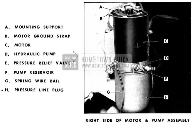
1952 Buick Hydro-Lectric Motor and Pump Assemblx
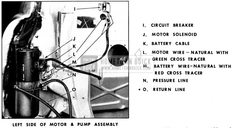
1952 Buick Left Side of Motor and Hydro-Lectric Pump Assembly
* Pressure line plug “H” remains plugged on all styles. Return line “O” is used on convertibles only (for the folding top lift cylinders). On other styles, it is plugged.
PRESSURE RELIEF VALVE
1952 Buick Pressure Relief Valve
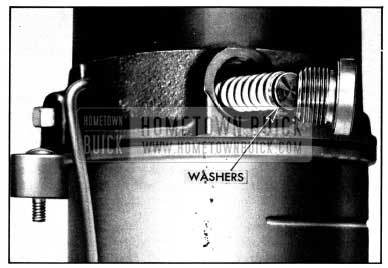
The pressure of the fluid in the hydraulic lines is controlled by a spring loaded pressure relief and flow control valve. When pressure in the lines reaches a maximum of 250 PSI to 260 PSI (e. g., the window reaches the full up position), the relief valve will open and allow fluid to by-pass into the reservoir rather than build up enough pressure to damage the lines. The pressure can be varied by adding washers between the valve stop and the spring as shown to increase pressure or by removing washers to decrease pressure. Under no circumstances should the pressure be changed to provide a pressure higher than 260 PSI. When cleaning or servicing the valve, make sure the same number of washers are added before installing the valve in the pump.
CHECKING FLUID LEVEL
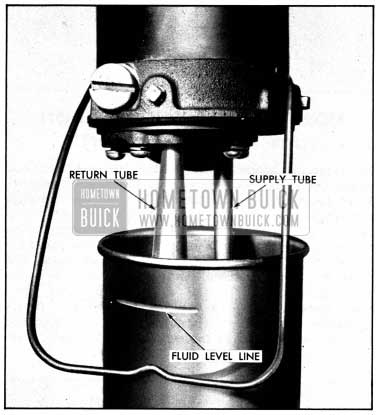
1952 Buick Checking Fluid Level
- Lower the top, operate the seat to the maximum rearward position and operate the windows to the fully lowered position.
- Disconnect positive terminal of battery to prevent accidental pumping of fluid.
- Move spring wire bail out of position and lower the reservoir from the pump assembly to inspect the fluid level.
- If necessary, add fluid to the reservoir to bring the fluid level to the indicated marker on the reservoir. Always use the recommended hydraulic fluid.
- Replace the reservoir, spring wire bail and positive terminal of the battery.
A plastic bag is installed to the pump and reservoir with tape in the 1952 Buick body assembly plant. This bag fits up around the complete reservoir and pump to catch any fluid leakage that might occur during transportation of the bodies and the completed automobiles to their destinations. It is removed and disposed of prior to delivery of the car as it has no further functional value.
THE HYDRAULIC PUMP
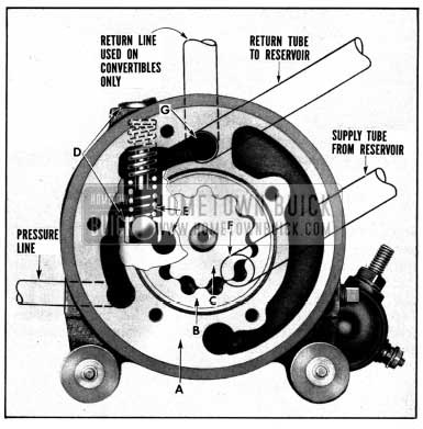
1952 Buick Hydro-Lectric Hydraulic Pump
The hydraulic pump operation explained in the following paragraphs concerns the “solid type” internal rotor pump. The operating principles of the other pumps used on 1952 Buick Hydro-Lectric installations are the same as explained herein.
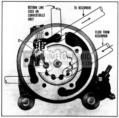
The hydraulic pump consists of a pump housing “A” which contains the free moving external rotor “B” and the motor driven internal rotor “C”. The pressure relief valve “D” extends into the housing to control the fluid flow through the cavities “E” in the housing. An end plate is attached to the pump housing to cover the rotors and fluid cavities. The end plate has a fluid supply tube and a return tube (see above illustration) that extend into the fluid reservoir. The supply tube opens into the area indicated at “F” and the return tube opens into the area “G”.
HYDRAULIC PUMP OPERATION
NON-OPERATING POSITION (OR LOWERING A WINDOW)
1952 Buick Hydraulic Pump Operation
When the motor is not energizing, the pump is in the non-operating position with the rotors remaining idle and the pressure relief valve in its normal position as shown in the opposite illustration.
This is the position of the pump when a window is being lowered or the seat is being moved rearward (no fluid is pumped for these operations). The fluid in this case returns via the pressure line, goes through the pressure relief valve spring as indicated by the arrows, and drains into the reservoir.
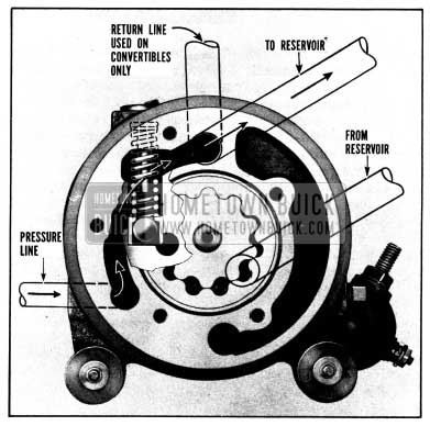
NORMAL OPERATING POSITION (OR RAISING A WINDOW)
1952 Buick Normal Operating Position
To raise a window, the motor is energized and starts the pump rotors moving in the direction shown. Fluid from the supply tube “F” fills the openings between the lobes of the rotors and is carried to the cavity “E” where it is forced out from between the rotors and builds up pressure against the pressure relief valve “D” which will then open as shown and allow the fluid to enter the pressure line to raise the window. This is the same action that takes place when the top is operated except that in the operation of the top, fluid from the top operating cylinder is routed down the return line into the reservoir at the same time.
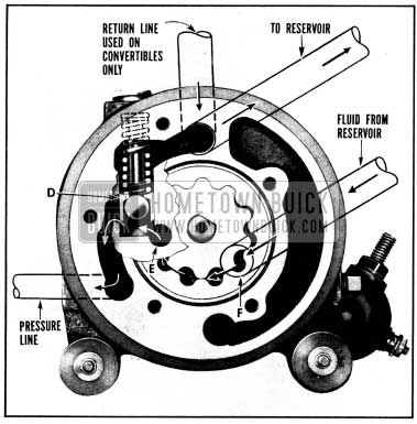
OPERATING AT MAXIMUM PRESSURE (WHEN WINDOW IS FULLY RAISED)
1952 Buick Operating at Maximum Pressure
When the window reaches the fully raised position, pressure builds up to a maximum of 250 PSI to 260 PSI. In this case, the pressure relief valve “D” is pushed down still further until the ball is unseated and allows fluid to escape through the valve to the reservoir. This valve action keeps the pressure from going above the maximum setting and causing damage to the system.
Leave A Comment
You must be logged in to post a comment.