DYNAFLOW OIL LEVEL & DIPSTICK CHANGE
Following is a reprint of Special Service Letter – Dealer No. 218, dated August 16, 1957, which includes corrected serial numbers as described in Special Service Letter, Dealer No. 218A dated August 20, 1957:
Listed below by assembly plants are serial numbers of the first cars equipped with a new Dynaflow oil gauge rod which is now being used in production as a result of Dynaflow oil level being increased by one (1) pint.
Serial No. – Assembly Plant
D1139233 – Flint
D2037335 – South Gate
D3045414 – Linden
D4043614 – Kansas City
D5038291 – Wilmington
D6039725 – Atlanta
D7018311 – Framingham
D8028593 – Arlington
The additional oil eliminates the occasional slipping condition reported on some jobs.
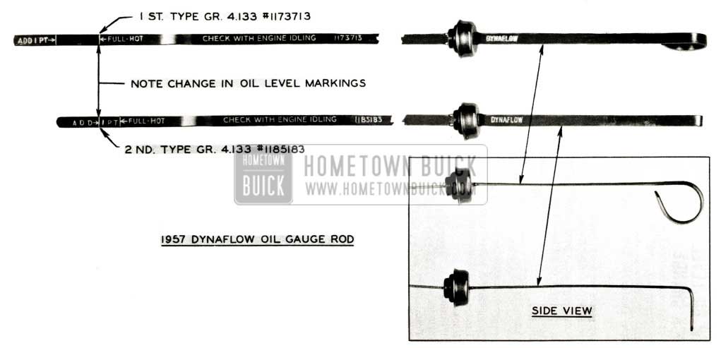
1957 Buick Dynaflow Oil Gauge Rod
Figure 43 shows the first and second type rods. Please note that they can be identified without removing them from the Dynaflow and that ”ADD 1 Pint” mark on new dipstick is placed where FULL mark on old dipstick used to be. This arrangement will help insure proper oil level and minimize the slipping problem mentioned above.
We would like each dealer to change these rods on the following basis:
- Order sufficient rods to change 50% of the total Dynaflow equipped cars delivered or in stock. The part number of the new rod is Group 4.133, Part #1185183. These rods will be shipped to you no charge. The reason for supplying the new rods at no charge is to eliminate the need for submitting an AFA.
- Install the new rod when the Dynaflow oil level is checked as the car is lubricated. We ask that this be done on all 1957 Dynaflow equipped cars regardless of who sold the car.
- Destroy the old rod.
- Any Dynaflow oil used to bring the level to the new full mark should be paid for by the owner.
- When the first 50% of the rods are installed, order as many more of the new rods as necessary to complete the change on all cars sold.
- Be sure to check oil level with engine at normal operating temperature and engine idling, with shift lever in Park position.
Your cooperation in getting these rods changed on all 1957 cars will be greatly appreciated.
DYNAFLOW OIL LINE LEAK
1957 All Series
Several product reports received have indicated that Dynaflow oil cooler pipe leaks occur where the steel oil pipes are joined together with a short piece of rubber hose near the radiator. It was found that two (2) different screw type hose clamps were used at this location, one having a solid wide band and the other having a band containing a slot. The clamp with slot is the one giving the most trouble, therefore, it is no longer being used at this location in production and only the wide band clamp fs specified. Whenever leaks of this type are encountered, it is advisable to make certain that only the wide band clamp is installed. The Parts Department is now handling only the wide band clamp available under Gr. 6 .671 Part #5684204.
PLANET CARRIER THRUST WASHER
We are still receiving inquiries whether or not the 1956 and 1957 Dynaflow transmissions are equipped with thrust washers between the planet carrier and case.
In the past on 1948 through 1955 the Dynaflow transmission used rear planet carrier thrust washer Gr. 4.176 Part #1334100.
In 1948 through 1953 and 1954 first jobs, planet carrier thrust washer front Gr. 4.176 Part #1333095 was used.
The 1954 after jobs including all1955 transmissions, do not use the front thrust washer and the 1956 and 1957 transmissions do not use either thrust washer (front or rear) at this location, therefore, NO ATTEMPT SHOULD BE MADE TO INSTALL THEM.
STICKING STATOR CONTROL VALVE
We have been advised by Engineering that on some very early 1957 Dynaflows the stator control valve in the high accumulator may stick in the down position, which will allow stator blades to remain in the high angle position at all times. This condition will evidence itself by abnormally high engine speed during part throttle operation in drive range, and failure of observing sudden increase in engine RPM when accelerator pedal is fully depressed with lever also in drive range.
If this condition is suspected, adjust stator control linkage as described in paragraph 3-6 on page 8 in the 1957 Product School Manual, then recheck operation of Dynaflow and variable pitch operation of stator. If switch of stator blades is still not observed in drive range and stall speed is approximately 2800 to 3000 RPM, it is an indication that stator valve is stuck, holding stator in high angle. In this case, remove the high accumulator and replace the stator control actuating valve assembly which is available under Gr. 4 .122 Part #1179828.
Also, on some early 1957 high accumulators a belleville type washer was used between the stator valve operating lever and bearing nut. It was found that the added resistance of this washer was sufficient, in a few cases, to prevent valve crank from returning to its normal position, thereby holding stator valve in high angle position. It is suggested, therefore, that the belleville washer be removed and discarded whenever an accumulator is found to be equipped with one. Doing so will leave only the flat washer between stator operating lever and bearing nut. See Figure 44.
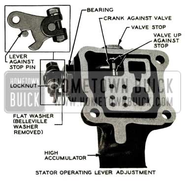
1957 Buick Operating Lever Adjustment
It is important when replacing the valve assembly to make certain that the accumulator and valve assembly are free of dirt or other foreign material which may cause valve to stick.
During re-assembly of the high accumulator, the adjustment of the stator operating lever on crank should be performed as follows:
With crank against actuating valve and valve in extreme upper position, the lever should be tight against stop pin when lock nut is tightened.
Flat rate time for replacing the stator actuating control valve is .5 hr.
The following component parts of the High Accumulator Stator Control Actuating Valve are presently listed in the current model Parts Book as separate service items:
Gr. 4.122 – 1173742 Valve-High Accumulator Stator Control
Gr. 4.122 – 1173746 Ring-High Accumulator Stator Control Valve Retaining
Gr. 4.122 – 1173748 Sleeve-High Accumulator Stator Control Valve
Gr. 4.122 – 1173764 Valve-High Accumulator Stator Control Actuating
Due to the nature of assembly of these parts, we have been advised by Engineering that they will not be listed as separate service items and only the valve assembly will be available as a service replacement part. Any stock you may have on hand of the above four parts should be returned to your warehouse for credit at once and all returns should be completed by November 30.
The new valve assembly which will be listed in the Parts Book for service replacements is as follows:
Gr. 4.122 – 1179828 Valve-High Accumulator Stator Control Actuating
These changes will be incorporated in the December 1 revision pages of the current model Parts Book.
SHIFT LINKAGE ANTI-RATTLE SPRING
Engineering advises that a new anti-rattle spring washer is being used in production on the shift linkage. This new washer Gr. 4.019 Part 1180307 has been released for service and may be used in cases where the shift linkage is rattling. This information supersedes the information contained in BPS 2.416 pertaining to shift linkage rattles.
CLUTCH ADJUSTMENTS
1957 Synchromesh
We have received comments from dealer mechanics to the effect that 1957 Synchromesh clutch linkages should be adjusted whenever the transmission has been removed and reinstalled. Engineering advises that, once correctly adjusted, removing and installing the transmission should not throw the linkage out of adjustment. However, clutch pedal lash (free pedal) should always be checked and if not 1 1/8″ to 1 1/4″, it will then be necessary to adjust the clutch linkage.
If an adjustment is necessary, follow the step by step procedure in paragraph 4-4 (a) of the 1957 Buick Chassis Service Manual.
EXCESSIVE CLUTCH PEDAL LASH
Clutch Release Rod Too Long
A few 1957 early production Synchromesh cars were built in which the clutch release rod used was 1/4″ longer than the rod now used in present production. This longer rod can cause difficulty in making a clutch pedal lash adjustment.
When adjusting clutch pedal lash, if the release rod bottoms in the release rod adjusting end, thereby preventing proper adjustment, correct this condition by cutting 1/4″ off the threaded end of the clutch release rod. See Figure 4-4 in the 1957 Buick Chassis Service Manual.
SYNCHROMESH TRANS. R&R
REMOVAL AND INSTALLATION OF S-M TRANSMISSION
Removal of Transmission
- Disconnect rear axle assembly and move it back out of the way. CAUTION: Be sure torque tube guide pins are installed before moving axle assembly back.
- Drain transmission lubricant. Fill with kerosene and run transmission in neutral for about 15 seconds. Drain cleaner.
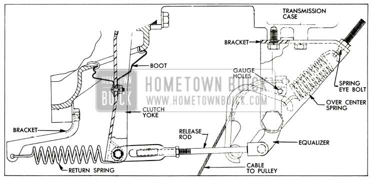
- Remove clutch linkage shield. Install a 1/4″ x 2 1/2″ bolt and nut finger tight in gauging holes of clutch equalizer and bracket. See Figure45.
1957 Buick Synchromesh Transmission Schematic
CAUTION: Unless equalizer is thus immobilized over-cent e r spring may cause hand injury when release rod and clutch equalizer bracket are disconnected.
1957 Buick Synchromesh Transmission Case
Remove lower bolts and move transmission straight out until clear of clutch housing and lower to floor. CAUTION: If weight of transmission is allowed to rest on main drive gear in clutch driven plate hub, driven plate may be damaged.
Installation of Transmission
- Lightly coat the splines on end of main drive gear with Lubriplate for a distance of not more than 1”. Do not apply an excess that will push off at driven plate hub and get on driven plate facings.
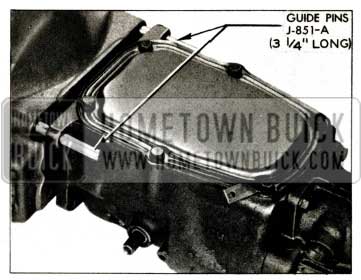
- Make certain that front face of transmission case and face of flywheel housing are absolutely clean. Install Guide Pins J -851-A in upper bolt holes in housing (fig. 46) and install a new transmission gasket. Make certain that spring washer is in place behind clutch release bearing support in housing.
- Lift transmission into place and fully support it until the main drive gear bearing enters flywheel housing. Clutch driven plate may be damaged if weight of transmission is allowed to rest on main drive gear in driven plate hub.
- Install lower transmission attaching bolts, then the upper bolts, and tighten all bolts evenly and securely. CAUTION: If a gap exists between transmission case and flywheel housing do not tighten bolts as case may be broken. Remove transmission and check position of main drive gear bearing snap ring, which may have slipped out of place during installation.
- Install transmission support with shims in original location. Shims should be of proper number and thickness to just fill space between support and frame.
- Lower the transmission to rest on the support and attach mounting pad to support with bolt plate and two self-locking nuts. Attach thrust pad to transmission thrust bracket with bolt plate and three self-locking nuts. Then tighten all nuts alternately and securely.
- Connect speedometer cable.
- Connect lower shift rod and selector rod to their levers.
- Inject 1/2 pint of transmission lubricant into torque ball through universal joint splines. Then fill transmission to filler plug level with approximately 2 pints of lubricant.
- Install rear axle assembly.
- Road test car, checking for proper selection and shifting of transmission, correct synchronization, and quiet operation of gears, bearings and shifter yokes. In neutral the lower control shaft lever should be midway in the mast jacket opening. It may be necessary to adjust transmission shift controls as described below.
ADJUSTMENT OF S-M TRANSMISSION SHIFT CONTROLS
All adjustments are made with the transmission in neutral and in position for shifting into second or third gear.
- With adapter assembly forced against flexible coupling flange, raise or lower jacket clamp until selector control lever pivot bushing clears control shaft lever by 7/16′ ‘. Then tighten clamp securely.
- Adjust shift rod trunnion so that control shaft lever is midway in jacket opening with transmission in neutral.
- Adjust selector rod trunnion so that with selector lever (on transmission) and selector rod both held to the rear, trunnion pin will freely enter hole in selector lever. Then lengthen selector rod by rotating trunnion one turn for proper adjustment.
- Shift transmission into each gear to check for proper shifting and to check control shaft lever clearance in mast jacket opening.
NEW COUNTER GEAR THRUST WASHER
1957 Synchromesh Trans.
Engineering has advised us that a new counter gear thrust washer Gr. 4.442 Part 1180482, has been designed, which greatly reduces wear.
The new washer has a pin in it which fits into a slot in the transmission case. See Figure47.
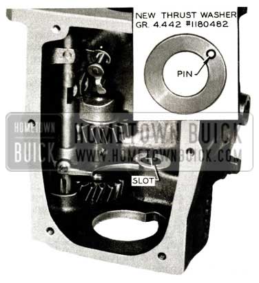
1957 Buick Synchromesh Transmission Counter Gear
Whenever a 1957 Synchromesh transmission is disassembled it is recommended that the new thrust washer Gr. 4.442 Part 1180482 be installed. However, in some cases (on early product cars) it may be necessary to deepen the slot in the transmission case so that the end of the pin does not bottom.
CARBON TYPE FRONT PUMP OIL SEAL
Dynaflow Gr. 4 .224 Part 1174916
We have received a few reports stating that after this seal was installed a squeak developed. Investigation revealed that in these instances it was caused by the seal inner retainer contacting the pump hub. This is a result of the seal not being fully seated in pump body during installation. When the seal is not fully seated a greater compression is applied to the carbon element and it is possible for the seal inner retainer to contact the pump hub.
Therefore, it is important whenever installing the carbon seal to follow installation instructions given in BPS Bulletin 2.412 dated Sept. 15, 1956, and make certain that seal is fully seated in pump body as mentioned above.
“O”RING FOR VALVE BODY SCREEN
Following is a reprint of Special Red Band Service Letter – Dealer No. 198 dated January 22, 1957 covering Dynaflow Valve Body Screen ”O’ Ring – 1957 Models.
To help prevent oil from by -passing the valve body screen at openings indicated by heavy arrows in Figure 48, „O“ ring, Group 4.224 Part No. 1336936, is being installed around the perimeter of the screen in production. This change was included in Dynaflow transmissions, starting with identification number 074, and will continue until a later date at which time the oil screen design will be changed and the „O“ ring omitted. Whenever a Dynaflow is on the bench or if, for any reason, the oil pan is removed with transmission in the car, it is recommended that the above mentioned ”0” ring be installed as shown in Figure 48.
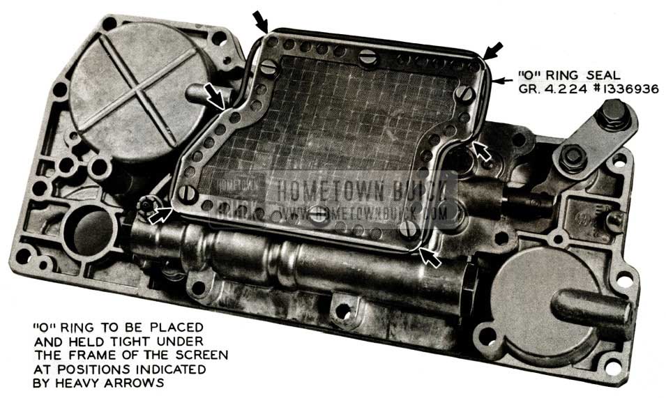
1957 Buick Valve Body Screen
To properly install the „O“ ring, loosen oil screen screws and press ” 0” ring under screen frame at six (6) locations indicated in Figure 48, by heavy arrows; then, firmly tighten screws to hold „O“ ring in position.
This is not a campaign and the installation of the „O“ ring is recommended only when other Dynaflow work is involved as mentioned above.
Flat rate time allowed for installing the “O” ring with oil pan removed is .1 hr.
DYNAFLOW LINKAGE ADJUSTMENT
1957
If a Dynaflow transmission does not shift properly, the shift control linkage adjustment may easily be checked as follows:
- Move manual control lever carefully until transmission is shifted into its Drive detent position (manual lever will seem to catch).
- Now move manual control lever toward Neutral (without lifting toward steering wheel) and notice how far it moves before contacting stop.
- Move manual control lever until transmission is in Low detent position.
- Then move manual control lever toward Reverse and notice how far it moves before it contacts stop.
- If movement from Drive detent to stop is the same as movement from Low detent to stop, shift control linkage is correctly adjusted.
If above check showed linkage to be incorrectly adjusted, adjust linkage as follows:
- With manual control lever left in Drive, raise car to get at linkage adjusting clevis on lower shift rod.
- Loosen clevis lock nut. Remove clevis pin along with cotter key and spring washer.
- Make sure transmission shift lever is in Drive detent (center position of 5 possible detents).
- Move idler lever so that upper shift rod is forced upward as far as possible. Then turn clevis until clevis pin will just slip in place without moving transmission shift lever.
- Shorten lower shift rod by turning clevis 4 complete turns.
- Install clevis pin spring washer and cotter key.
- Lower car and recheck adjustment at manual control lever as described above. If movement from Drive detent to stop is still not the same as movement from Low detent to stop, readjust lower shift rod clevis slightly until movement is even.
- After adjusting Dynaflow shift control linkage, always make sure that control dial pointer lines up with letters on face of dial.
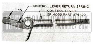
LOOSE DYN. SHIFT CONTROL LEVER
We have received dealer product reports on a few early 1957 models stating that the Dynaflow shift control lever could be moved from Park position to Reverse position without lifting lever, and no definite stops at any point between these two positions were observed. This condition is the result of a broken or worn pin used at end of shift lever to engage stop in control housing. If this condition is encountered, it can be corrected by installing a new shift control lever Gr. 4.035 Part #1174493.
The lever can be removed by removing the control lever to housing pin retainer driving out pin. Then pull the control lever out, toward the steering wheel to remove it. CAUTION: When removing the lever, care should be taken to keep the transmission control lever return spring from flying loose.
Position the control lever return spring on the lever as shown in Figure 49.
1957 Buick Dynaflow Shift Control Lever
Insert Phillips screwdriver through the spring coils and hole in lever, then insert the lever into control housing. Using needle nose pliers, rotate each end of return spring into the control lever housing See Figure 50.
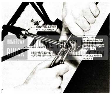
1957 Buick Dynaflow Shift Control Lever Repair
When the spring is in housing, push the lever inward until screwdriver makes contact with housing, then remove the screwdriver and push the lever in until the lever retaining pin may be driven into position. Install shift lever pin retainer by rotating it on lever housing to lock it in position.
TORQUE BALL RETAINERS
1957
Due to the unavailability of the 1957 Torque Ball Inner and Outer Retainers at the start of production, it was necessary to use the 1957 After-Jobs Torque Ball Retainers on the first 1957 cars which were built. The 1957 Torque ball Retainers will be used in production as soon as they become available.
The 1957 current model Parts Book lists only the 1957 Torque Ball Retainers but will be revised with the December 1 supplement to show the first and after-jobs parts which were used. It will be necessary to determine what type of Torque Ball Retainers are on the car when ordering replacement parts. See Figure 51.
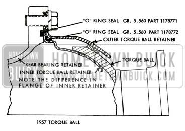
1957 Buick Torque Ball Retainers
Following are the parts involved:
Torque Ball Retainers on 1957 First -Jobs
Gr. 5.560-1163932 – Retainer-Torque Ball Inner
Gr. 5.560- 1168452 – Retainer-Torque Ball Outer
Gr. 5.560 -1169442 – Gasket-Torque Ball Retainer (Between Inner and Outer Torque Ball Retainers) Gr. 5.560-1168453 – Reinforcement-Torque Ball Retainer
6- Bolt-Hex. Head 3/8-16 x 1 1/4 (Torque Ball Retainers to Rear Bearing Retainer)
Torque Ball Retainers on 1957 After-Jobs
Gr. 5.560- 1178769 – Retainer-Torque Ball Inner
Gr. 5.560-1178770 – Retainer-Torque Ball Outer
Gr. 5.560 -1178772 – Ring-Outer Torque Ball Retainer Sealing (Between Inner and Outer Torque Ball Retainers)
6- Bolt-Hex. Head 3/8-16 x 7/8 (Torque Ball Retainers to Rear Bearing Retainer)
Note: Both first and after job torque ball retainer arrangements used Gr. 5.560 Part 1178771 Ring Torque Ball Flange Sealing which is new for 1957 and fits in a groove in the rear face of the rear bearing retainer.
DYNAFLOW OIL COOLER CHECK
It has com e to our attention that Dynaflow oil coolers (lower radiator tanks) are being replaced even though they do not leak when subjected to tests at the authorized radiator repair shops.
Reports recently received indicated that over 90% of the coolers that were replaced did not leak. In view of this, we are requesting that dealer service men take the necessary precautions against unnecessary removal of the radiator from the car and that a very close inspection first be made to determine if the cooler is actually leaking.
In order to avoid any unnecessary replacements of radiators or lower tanks the following procedure may be used:
- Disconnect cooler lines at bottom tank.
- Insert a plug in one of the transmission oil cooler inlet or outlet fitting and in the opposite fitting insert a plug or fitting with an opening that will accommodate an air test hose.
- After both the inlet and outlet fittings have been plugged, completely fill radiator with water.
- With radiator completely filled, apply 100 to 150 psi maximum air pressure to the transmission oil cooler and observe if air bubbles are coming out the radiator filler neck in a continuous stream. If a continuous stream of bubbles is observed, it indicates that the cooler tank has a leak and should be taken to the nearest UMS dealer for repairs.
Radiators which do not leak when tested by the authorized radiator shop will be returned to the dealer.
NEW DYNAFLOW SPRAG
1957
A new Dynaflow Sprag Clutch went into production starting with Transmission number 04 7, as an after job change in 1957. This new sprag contains two bronze drag strips which provides a bearing surface that rides on the reaction shaft when freewheeling to reduce reaction shaft wear. See Fig. 52.
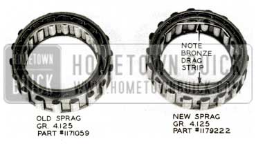
1957 Buick Dynaflow Sprag
The inner cage of the sprag has also been increased in diameter; however, it is interchangeable with the 1956 Dynaflow Transmission.
The Parts Department advises that stock of the new sprag Gr. 4.125 Part #1179222 is readily available.
DYNAFLOW OIL PAN LEAK
Several product reports have indicated Dynaflow transmission oil leaks on 1957 cars occurred at the oil pan gasket. We have now been advised that the oil pan bolts should only be torqued 10 to 12 ft. lbs. Therefore, will you please change the torque specification for the Dynaflow oil pan bolts listed on Page 5-2 of the 1957 Chassis Service Manual to read 10 to 12 ft. lbs. instead of 15 to 18 ft. lbs.
Excessive torquing of these bolts will damage the gasket as the reinforcement flange formerly used on the pan is not used on 1957 cars.
DYNAFLOW SHIFT CONTROL VALVE ADJUSTMENT
In line with information contained in BPS 2.422 on the new valve and valve body, a revised procedure for shift valve adjustment has been developed. This procedure which applies to 1955,
1956 and early 1957 Dynaflows eliminates one step previously contained in adjustment instructions. Starting with Step #8, subparagraph g, in paragraph 5-23 of the Shop Manual should read:
- Temporarily install shift lever on cross shaft and operate valve to make sure it works freely. Move lever to engage middle detent (Drive position).
- If inner end of valve is not flush with edge of port in valve body, loosen lock bolt and move adjusting lever as necessary to align edge of valve with edge of port {flush), then re-tighten lock bolt, making certain that adjustment does not change. See Figure 53.
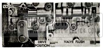
1957 Buick Dynaflow Shift Control Valve Adjustment
Continue at this point with step 13.
For 1957 after jobs see the following article “New Dynaflow Valve Body and Shift Control Valve” page 51, plus steps 10 and 11 of above procedure.
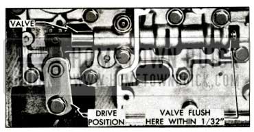
NEW DYNAFLOW VALVE BODY & SHIFT CONTROL VALVE
We have been advised by Engineering that a new valve body and valve are being used in production, starting on March 5th with transmission #R -109. The new valve body prevents the oil from being dumped above the screen as the ports in the body have been eliminated. Therefore, all oil is filtered through the screen before it enters the hydraulic circuits of the transmission. Obviously, by doing this, foreign material is less likely to enter the working parts of the transmission and cause subsequent failure. The new and the old type valve and bodies may be seen in Figures 54 and 55.
1957 Buick Dynaflow Valve Body
1957 Buick Dynaflow Shift Control Valve
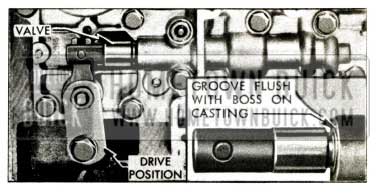
The service procedure for adjusting the shift control valve in the new valve body has been changed since the land on the new valve is no longer visible through the discharge port. To facilitate adjustment, the new valve has a locating groove which is to be positioned flush against the boss on the casting with the shift lever in drive position and the adjusting lever tightened as on previous models. See Fig.55.
Either type valve or valve body can be used and adjustments may be made as follows: A new type valve may be used in an old type valve body, in which case the valve may be adjusted by using the present procedure or that listed above. However, if an old type valve (without the locating groove) is to be used in a new valve body, first locate the replacement valve in drive position in an old valve body as shown in Fig. 54. Then, mark on the old valve in the same location of groove on new type valve. This mark may then be used as a reference point to adjust the old valve in the same manner as the new one in drive position.
VALVE BODY CHANGE
(1957 – Dynaflow)
Early 1957 Dynaflows were equipped with a valve body, Gr. 4.265, Part No. 1172012, which has a 1/8” diameter vent hole located as shown in Figure 56.
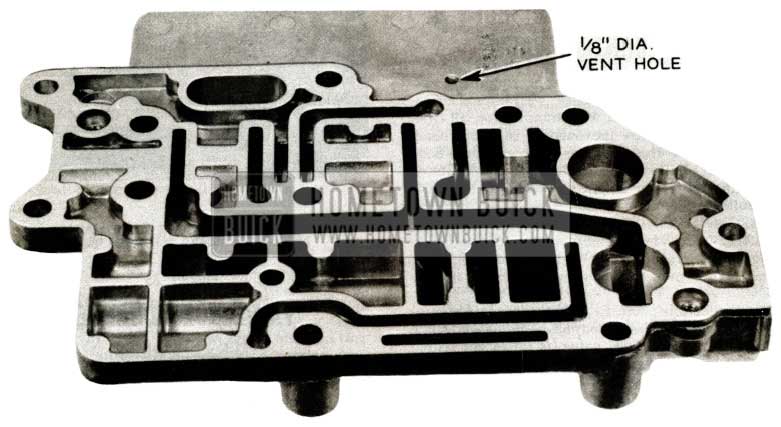
1957 Buick Valve Body
The purpose of this hole is to allow air to escape from the area above the oil screen when the transmission is filled with oil. It was felt that this design would prevent air from becoming trapped and being drawn into the suction lines, causing a drop in oil pressure. Although the vent hole serves this purpose, there is a possibility during cornering that the oil in the shallow pan could collect on one side and leave the vent exposed to atmosphere, and allow air to be drawn into the suction lines. Therefore, to eliminate this possibility, Engineering has made a change in production to plug the original vent hole and relocate it in the rear pump suction passage. Whenever the Dynaflow oil pan is removed, it is recommended that the valve body be removed and the vent hole relocated as shown in Fig. 57, and the old vent plugged with a self-tapping screw. It is important that the rivet or screw be installed as shown to prevent the possibility of it falling out and becoming drawn into the suction oil line.
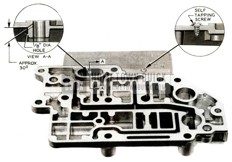
1957 Buick Valve Body Overview
Valve bodies Part #1172012 on hand in dealers stock should be reworked before installation as outlined above.
When stock of valve body 1172012 is exhausted, the new valve body with relocated vent hole will be shipped. At a later date, the valve body casting will have the old vent hole completely eliminated and a new vent cast into the rear pump suction gallery. These valve bodies will be listed under a new part number.
Flat rate time allowed for plugging valve body vent hole is 1.3 hr. Including R&R oil pan.
Leave A Comment
You must be logged in to post a comment.