CARTER CARBURETOR SPECIFICATION CHANGES
Following are the latest Carter carburetor specifications for 1957. Rather than list the individual changes, we are reprinting all the specifications for the model WGD two-barrel and AFB four-barrel Carter carburetors; therefore, the information on Carter carburetor listed in BPS 2.415, dated November 9, 1956, should be disregarded. NOTE: Only those items identified by an asterisk are affected by the specification change.
CARTER CARBURETOR & CHOKE CALIBRATIONS
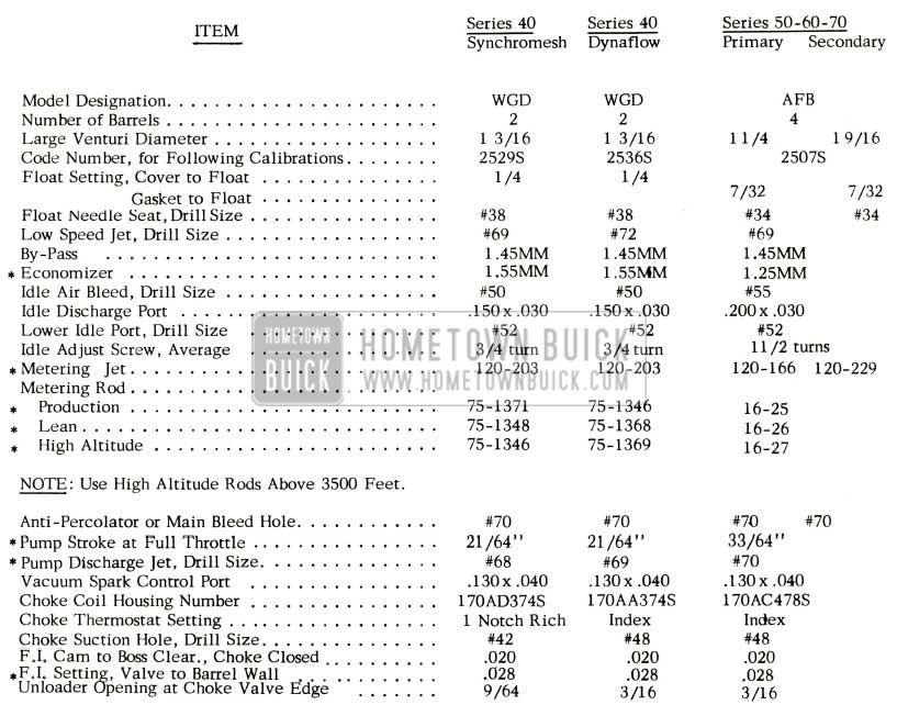
1957 Buick Carter Carburetor Calibrations
IMPORTANT: Calibrations are governed by the CODE number on the attached code tag.
ROCHESTER CARBURETOR AND CHOKE CALIBRATIONS
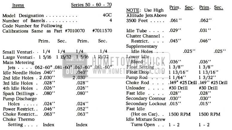
1957 Buick Rochester Carburetor Calibrations
IMPORTANT: Calibrations are governed by the CODE number on air horn.
STROMBERG CARBURETOR AND CHOKE CALIBRATIONS
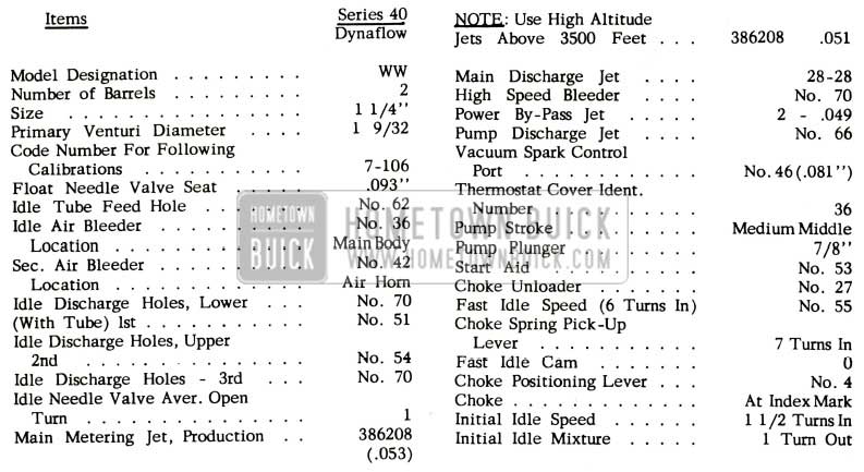
1957 Buick Stromberg Carburetor Calibrations
IMPORTANT: Calibrations are governed by the CODE number stamped on air horn.
CARBURETOR CHANGES
Due to the large number of changes in the 1957 carburetors all previous bulletins will be condensed into this one article in an effort to clarify all changes and make them more useable.
In the article we take each carburetor and start with the first change on the first production jobs and take each change separately bringing the carburetor up to present production models.
ROCHESTER 4-BARREL
Two (2) Rochester four-barrel carburetors have been used in 1957 and they may be identified by the Part numbers on the identification tag which are: 7010070 and 7011570.
Six modifications have been made on the Rochester carburetor 7010070 up to this date. These changes are designated by a letter stamped on the identification tag. On the bottom line of the tag there are three character markings. The first character is a letter, this letter indicates the production modification incorporated in the carburetor; ”A” indicates the first modification, “B” the second, “C” the third, etc. See Figure 16. The second character is also a letter. This letter indicates the month in which the carburetor was built. “A” indicates January, “B” February, etc. See Figure 16 .The third character is a number and indicates the year in which the carburetor is built. “6” indicating 1956, “7” 1957, etc. See Figure 16. The six (6) modifications are as follows:
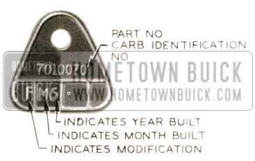
1957 Buick Rochester Carburetor Identification
”A” Designates a calibration change in the throttle body to improve metering. Only one-hundred (100) carburetors were built before this change was made. No service fix was given for this change.
“B” In this change the float drop setting was changed from 1 7/8 to 1 13/16 to correct fuel level which was too high. In service this is corrected by following the procedure as outlined in the 1957 Chassis Service Manual, Paragraph 3-31, Sub Paragraph (a) Step 16, using the new specifications.
”C” The idle channel restriction in primary venturi cluster was changed. This change was made in order to improve a lean mixture condition at a steady speed at 20 to 40 MPH. In service this change was taken care of by installing the cluster kit.
“D” Constitutes a change in the choke housing. This change provides a more easily seen index mark on the thermostat cover and choke housing for adjustment purposes.
” E” Power restrictions w ere changed to improve desired wide open throttle mixture. There was no service fix given for this change.
“F” This modification changed the design to overcome a heavy 3/4 throttle acceleration sag or surge. This condition was overcome by a new secondary venturi cluster, secondary main metering jets, and pump lever and rod. In service this condition was taken care of by installing the parts mentioned above which were available in a carburetor modification kit.
“G” This change was designed to eliminate any remaining trace of heavy acceleration ”sag” that has not been overcome by change “F” and to eliminate part throttle and tip -in acceleration leanness. This was accomplished by a new auxiliary valve body assembly, primary metering jets, enlarging primary idle tubes, and enlarging primary power restrictions.
At this point it was decided that all these changes should be incorporated and that the carburetor be given a new part number or identification number 7011570; therefore, all carburetors having this number will have all the above changes in it.
The modification designated by “A” on the 7011570 carburetor consisted of larger main metering jets and idle tubes on the primary side. This was done to eliminate part throttle and “tip-in” acceleration leanness. The tag will appear as shown in Figure 17.

1957 Buick Rochester Carburetor Identification Tag
On early 1957 Rochester Carburetors the discharge nozzles were pressed into the cluster to a point where a clearance of .106″ existed from tip of nozzle to bore wall in cluster. See Figure 18.
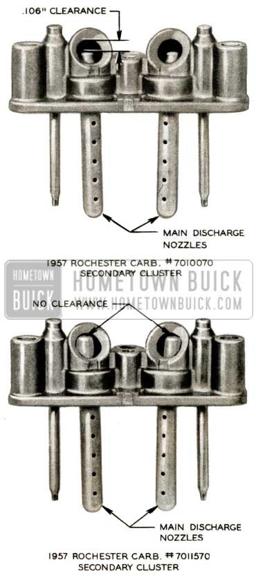
1957 Buick Carburetor Clearance
Starting with carburetor part number 7011570 the secondary nozzles were pressed in with tip of nozzle against the bore wall with no clearance. This was done to give faster response of the fuel in the secondary side when the secondary throttle valves were opened.
These late carburetors (#7011570), however, still have the primary cluster in which the tip of discharge nozzle is .106″ away from bore wall.
It was decided that if an owner was experiencing carburetor trouble with a Rochester Carburetor No. 7010070, or 7011570 NOT tagged with Code “A” a new carburetor package Gr. 3.725 Pt. 7015777 was to be installed. This package contains a carburetor mounting gasket & carburetor 7011570 having Code “A “on the tag and has been used in production starting with engine code #208502.
Starting with Rochester Carburetor (7011570) code number 07, the accelerating pump lever will have three (3) holes instead of two (2) to provide additional pump stroke adjustment if needed under certain conditions. This new lever is designed with a tang for retaining the pump rod in pump arm. See Figure 19.
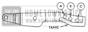
1957 Buick Carburetor Clearance Schematic View
- Hole “A” – All carburetors are assembled at the Factory with pump rod in this hole to provide satisfactory pump stroke for average conditions.
- Hole “B” – May be used to shorten pump stroke and prevent over-rich pump mixture which may result in stumble or hesitation during light acceleration in climates where temperatures do not exceed approximately 95° F.
- Hole “C” – May be used to shorten pump stroke further if slight hesitation is experienced during light acceleration with “B” setting. “C” setting is most suitable for operation in extremely hot climates where temperatures remain above approximately 95° F for long periods of time.
CARTER 4-BARREL
Since the beginning of 1957 production to present production the Carter 4-barrel carburetor has had three basic changes. These changes are as follows:
- Accelerator pump plunger spring – The new pump plunger spring will eliminate lean flat spot on light (tip in) acceleration. Note: The pump plunger spring is not available separately; however, a pump plunger equipped with the new spring is available under Gr. 3.838 Part 1172261 (Carter No. 64-209S).
- Secondary throttle operating lever, Gr. 3.759 Part 1180723 (Carter #53A-419) – This new lever is used to eliminate a lean or “sag” spot experienced when the engine is at normal operating temperature on one-half to seven-eighths throttle accelerations. When this lever is changed the following details should be noted:
- When installing lever secondary throttle return spring should be wound one (1) complete turn clockwise for proper installation. See Figure 20.
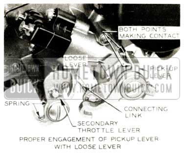
1957 Buick Carter Carburetor Clearance
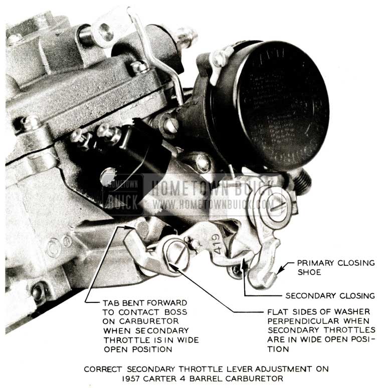
1957 Buick Throttle Lever Adjustment
All carburetors that were equipped with the “419” secondary throttle lever are being campaigned and adjusted as mentioned above. In order to help eliminate the possibility of this lever not being adjusted properly, it is being replaced with lever, Gr. 3. 759 Part 1182487 (Carter No. 53-A-430) which will be used on all carburetors coded E- 7 or later.
The first engine to be equipped as stated above with the first type secondary throttle lever, Gr. 3.759 Part 1180723, and the accompanying changes of modification kit, Gr. 3. 725 Part 1181392, may be identified by production code number 191412.
We have been advised by Engineering that Carter no longer uses the identification tags on four-barrel carburetors, but instead the identification number or production date code number (M-6, A-7, B- 7 ) will be stamped on the rear portion of the throttle body flange, as shown in Fig. 22.
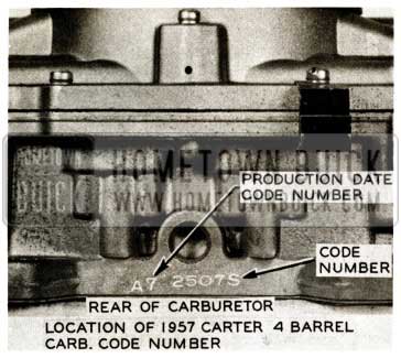
1957 Buick Location of Carburetor Number
We have also been informed that if the code number is pre fixed with an “X” such as XA7, the carburetor will have the change, outlined above. Also, approximately 2500 of early production Carter Carburetors (four-barrel) have no identification on them, in which case if difficulty is encountered, the modification kit, Gr. 3.725 Part #1181392, should be installed. , After this kit has been installed, please stamp or scribe the letter “X” on throttle linkage side of carburetor adjacent to accelerator pump, as shown in Figure 23.
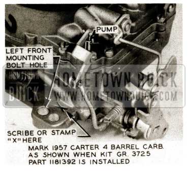
1957 Buick Mark on Carburetor Number
A number of early production Carter four-barrel carburetors are operating with the vacuum advance operating on idle , resulting in engine roughness and incorrect ignition timing. To determine whether or not vacuum advance is present when engine is idling at 485 RPM, disconnect vacuum spark line at throttle body and attach vacuum gauge to fitting on carburetor. If gauge indicates 5 or more inches of mercury, the one (1) throttle valve which operates vacuum advance unit must be replaced. This condition may exist only on carburetors coded K-6, L-6, M-6, and A-7 and if encountered, it may be eliminated by replacing the one (1) production primary throttle valve, Gr. 3. 758 Part 1179261 Carter #2 -186, on the vacuum spark take -off side only with throttle valve Gr. 3.758 Part 1181228 Carter #2-208. This pertains only to the above mentioned carburetors when the vacuum advance is operating at idle.
If for any reason the production throttle valves of carburetors K-6, L-6, M-6 and A-7 need replacement and the vacuum advance operation has been satisfactory, the standard throttle valve Gr. 3.758
Part 1179261 should be used. If, for any reason, carburetors code tagged B- 7 or later require replacement of the primary throttle valves, use only valves listed under Gr. 3.758 Part 1180722 as these carburetors have the spark hole in the throttle body relocated to eliminate and insure against having vacuum advance when engine is idling. Therefore, only valve 1180722 should be used as it is designed for use with the relocated hole.
CARTER 2-BARREL
The two-barrel Carter Carburetor which is used on Dynaflow equipped cars Model W.G.D. code number 2536S has not had a change in it. Therefore, the specifications in Bulletin 2.418 Page 65 are correct.
The Carter Carburetor which is used on 1957 Synchromesh cars, Model W .G.D. has had two changes made in it. These changes were made to eliminate two (2) conditions which were prevalent on those early cars. These two conditions were: (1) lean part throttle operation at 30 to 40 MPH, and (2) loading condition during warm-up.
Each of these complaints were corrected by the following:
- The lean part throttle condition at 30 to 40 MPH can be eliminated without removing carburetor from the car by installing kit Gr. 3.806 Part 1180737 which includes the following:
- Metering Rods
- Accelerator Pump Plunger Spring
Both parts are only available in kit Gr. 3.806 Part 1180737. However, accelerator pump equipped with the new spring is available under Gr. 3.838 Part 1180623. Because of the above change, it was necessary to replace the old carburetor repair package with a new repair package Gr. 3. 725 Part 1172263 which will contain all the new changes.
- The loading condition during warm-up may be corrected without removing the carburetor from the car by replacing the production automatic choke vacuum piston with the new choke piston Gr. 3. 752 Part
1179336, and changing the climatic choke setting from one (1) notch rich to one (1) notch lean. The fast idle adjustment must be made so that when the engine is thoroughly warm it will idle at 1800 RPM with the fast idle screw on the high step of the fast idle cam. Previous specification was 1500 RPM.
STROMBERG 2-BARREL
The Stromberg two-barrel Carburetor for 1957 has three changes since the beginning of 1957 production. These changes are designated by the letter which follows the model code number such as: 7-106-A, and 7-106-B. “A” designating the first, “B” designating the second change, etc.
The model code number of the Stromberg Carburetor is located on top of the float bowl. See Figure 24.
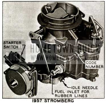
1957 Buick Stromberg Carburator
- – 7 -106-A – This change in the Stromberg Carburetor did not require service information since it consisted of a slight change in the float needle valve changing it from a pointed valve to a blunt ended valve. This has a tendency to improve the anti-vapor lock characteristics of this carburetor.
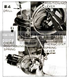
- – 7-106-B – In order to eliminate a loading condition on early warm-up it was necessary to change the choke positioning setting. This specification change constituted change “B”. In order to affect this change it was necessary to perform the following steps:
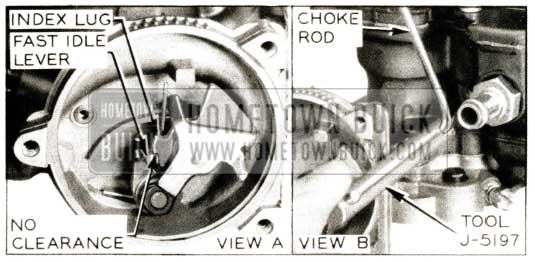
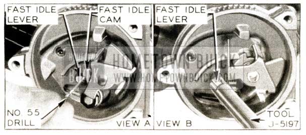
- Open throttle enough to clear fast idle cam and fully close choke valve. Then close throttle until fast idle lever rests on high step of fast idle cam. In this position there should be no clearance between the fast idle lever and the lug on the fast idle cam. See Figure 25. If there is clearance, bend choke rod as required to obtain correct adjustment using tool j-5197. See Figure 25.
1957 Buick Carburator Choke Rod
1957 Buick Carburator Positioning Lever
1957 Buick Carburator Idle Lever
Return throttle stop screw to normal hot idle setting of 485 RPM. NOTE: Flat rate time for above operation is .4 hr.
Below is a chart which gives all the main metering jets for Stromberg and Rochester and all the metering rods for the Carter Carburetors:
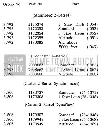
1957 Buick Carburator Specifications
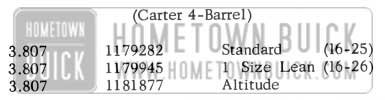
1957 Buick 4-Barrel Carburator Specifications
EXHAUST SYSTEM PRECAUTIONS
When Servicing Drive Line on 1957 Models
We have been advised by Engineering that in removing the transmission on 1957 Models an additional procedure must be employed to prevent abuse of the exhaust system. This procedure will prevent engine load from being carried by manifolds, manifold studs, and exhaust system; and in addition, will prevent “part throttle roar” from developing in cars due to binds in the exhaust system.
In operations in which the transmission is removed or disconnected and the rear of the engine is lowered, employ the following additional procedure:
- Prior to re moving the transmission, disconnect the exhaust pipes from the exhaust manifolds and loosen the front muffler joints.
- After the transmission is reinstalled, reassemble the exhaust system, making sure that pipes are centered in the frame member holes and that the system is free from binds.
To perform this work on 1957 Models, an additional .3 hr. will be allowed in the following Flat Rate Operations: 6-65, 6-710, 6-715, 6-720, 6-730, 6-740, 7-3, 7-5, 7-13, 7-32, 7-60, 7-63, and 7-64.
PART THROTTLE ROAR
1957 – All Series
The noise or vibration discussed herein is called “Part Throttle Roar”, and is objectionable in a very limited number of cars. Part Throttle Roar occurs during light acceleration from 20 to 35 mph between engine speeds of 1100 to 1750 rpm.
This vibration sometimes enters the body through the exhaust system mountings. It should be pointed out, however, that this is not the only possible point of entrance of Part Throttle Roar into the body. Any bound-up lines or metallic contacts between engine and body, or frame and body, are potential points of entrance.
Exhaust System
In many cases Part Throttle Roar can be either reduced or eliminated by freeing up and aligning the exhaust system. This can be accomplished as follows:
- Loosen the exhaust system ball joints very slightly so that the system can be moved with slight bar pressure, but will still support its own weight at the following locations:
- Exhaust pipe to manifold joint on dual cars, and front to rear exhaust pipe joint on single exhaust cars.
- Front muffler ball joint.
- Rear muffler ball joint.
- Loosen the clamp on the tailpipe hanger over the axle.
- Using a bar and slight pressures, pry the system so that any kinks are removed from the hangers, the pipes are centered in the frame member holes, and the system is not binding.
- Tighten the clamp on the tailpipe hanger, making sure the tailpipe is positioned with 3/4 to 1 inch clearance to the rear spring cross member flange.
- Tighten the exhaust system joints to a torque of 10 – 15 foot pounds, starting from the front and progressing to the rear.
AIR CONDITIONED CARS
An Air Conditioner-equipped car is subject to all the noise and vibration periods of standard cars. The additional Air Conditioner lines to sheet metal and dash make these cars more sensitive. It is necessary that all interferences between body and sheet metal to frame are eliminated. Also, the exhaust system should be properly aligned as established in this bulletin. It is sometimes necessary to repeat this alignment procedure to do a satisfactory job.
Listed are some of the interferences that might be encountered.
- Header bar contacting hood and fenders.
- Bumpers, front and rear, contacting sheet metal and body.
- Gas tank filler pipe contacting bumper or body.
- Exhaust system contacting frame or rear bumpers.
- Front fender skirts contacting frame, front body supports and left front brake pipe on top of frame.
- Undercoating shorting between frame and body, body shims, exhaust system joints and covering exhaust system.
- Screws driven through floor, contacting frame. Safety belts floor bolts contacting frame or exhaust system.
- Air Conditioning lines twisted, contacting sheet metal, contacting dash seam between floor pan and dash, contacting windshield washer body. Also power steering lines contacting sheet metal.
- Undercoating on pulleys throwing them out of balance.
- Improper installation of upper body shim, Part No. 1325095, in being placed across hole instead of through it. This does not allow rubber shoulder to extend through the frame, allowing the tube to contact both the frame and body.
Another source of roar on air conditioned cars is the fan. This is eliminated by the installation of the fan clutch which is now being campaigned in the field.
Compressor Noise
Compressors should not be checked for noise with the blower “OFF”. This is a condition under which the unit will not be doing any useful work and will allow liquid to be returned to the compressor. A compressor should only be considered noisy when it produces objectionable noises in the driver’s compartment with the blower on “Low”.
Many noises are contributed to compressor which will be eliminated if the car roar or vibration is eliminated. This is true because turning the compressor “On” and “Off” varies the engine speed. If the engine is operating in a “roar” period and the compressor is turned “Off” the engine speed increases and goes above this roar period. If the engine is re turned to this same speed with the compressor “Off”, the roar is still there. The only way to check this is with an engine tachometer.
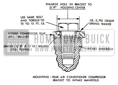
Vibration at low speeds in most cases may be reduced considerably by reworking the rear compressor mounting bracket as follows:
- Remove rear compressor bracket, Part No. 11 75088; then, using 5/8″ diameter drill, enlarge hole in which bolt secures bracket to intake manifold.
- Remove burrs and rough edges.
- Reinstall compressor bracket using spacer and spring washer under head of bolt at intake manifold location. See Figure 28.
1957 Buick Throttle Control
Spacer may be made from 1/2” diameter welded steel tubing cut to a length of 7/32”; spring washer is available under Gr. 0.792 Part #1302539.
Reworking the bracket as mentioned above will allow the engine to rock sideways without exerting pressure against the bracket and will reduce tendencies of transmitting engine vibration through the bracket at this location.
THROTTLE CONTROL RATTLES
We have received a number of complaints stating that the throttle control linkage rattles on 1957 models. This has been traced to insufficient lubrication on the upper and lower bearings in the equalizer brackets through which the equalizer shaft passes. If these bearings are not lubricated periodically, the shaft drags in the upper bearing when the engine rolls and the lower bracket assembly hammers on the retaining ring. Therefore, it is suggested to lubricate the bearings with lubriplate every time the chassis is lubricated (approximately every 1000 miles).
ACCELERATOR ROD BINDS
1957 Models
Several reports have been received stating that the accelerator rod strikes or binds where it passes through the hole in the toe -board panel. This condition has been corrected in production by enlarging the hole to 1 1/4″. Therefore, if conditions of this type are encountered on early 1957 models, enlarge the hole as mentioned above so that the accelerator rod is not contacting sheet metal.
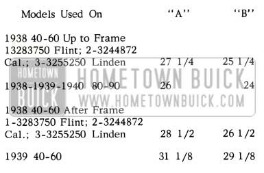
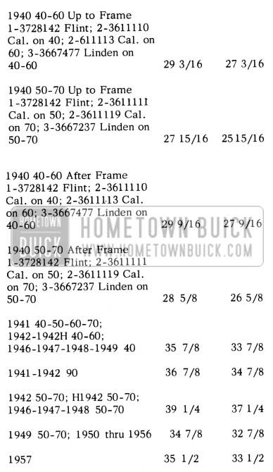
GASOLINE TANK SUPPORT STRAP
The service gasoline tank support strap lower, Gr. 3.022 Part 1337567, which has been used for replacements on 1949 and older models will now be used for all service replacements. The production type support strap, Gr. 3.022 Part 1339693, will be replaced by the service strap, Part 1337567, when stock on hand is exhausted.
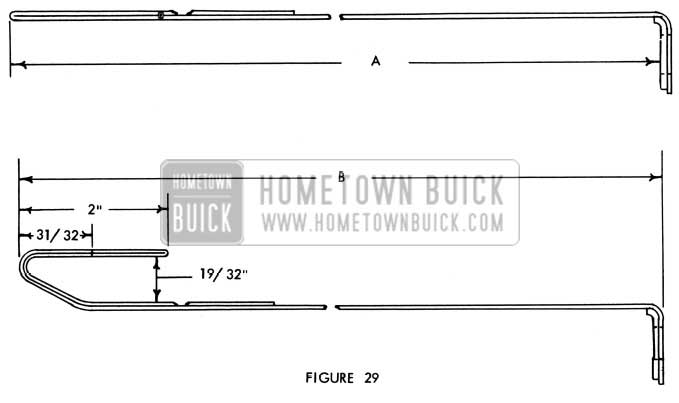
This service strap is stocked in the long length and must be bent to the required length at the time of installation. The rear end of this strap, through which the bolt extends, is the same as on the strap it is replacing. The gasoline tank support bolts will remain the same as specified in the Parts Book for the various models, and should be installed as they were originally on the car.
Figure 29 shows the method of bending this strap and following are the lengths required on the various models:
1957 Buick Gas Tank Support Strap Length
1957 Buick Gas Tank Support Strap Length Overview
1957 Buick Gas Tank Support Strap
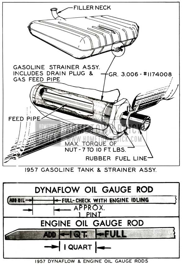
FUEL STRAINER & OIL GAUGE ROD
It is recommended that the fuel strainer be serviced every 5000 miles at which time the fuel tank should be drained and the strainer assembly (Gr. 3.006 Part #1174008) replaced if necessary. When servicing this strainer, the torque applied to the nut when tightening should not exceed 7 to 10 ft. lbs., as higher torque may break the fitting loose in the tank and cause a leak.
Also included in Fig. 30 is the 1957 engine and Dynaflow oil gauge rods. Note engine oil gauge rod marking has only “1 qt.” line as compared to a “1 qt.” and “2 qt.” lines of the 1956 rod. This, of course, is due to the one quart reduction in crankcase capacity.
1957 Buick Gas Tank Assembly
FUEL PUMP INSTALLATION
We have been advised by our Engineering Department that it is possible to damage the fuel pump during installation if the correct procedure is not followed. This is because of the change in design of the camshaft sprocket for 1957. When installing the fuel pump, it is possible to get the fuel pump arm wedged in between the fuel pump operating eccentric and the sprocket. See Fig. 31
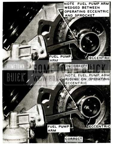
1957 Buick Fuel Pump Arm
Therefore, when the pump is bolted into this position, the arm is permanently distorted and the pump must be replaced.
When installing the fuel pump this difficulty may be avoided by rotating the engine until No. 5 cylinder is in the firing position. No. 5 cylinder is in firing position when the timing mark on the harmonic balancer is 90° or 1/4 a revolution past the “0” on the timing indicator, and the distributor rotor is in the position shown in Figure 32.
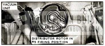
1957 Buick Fuel Pump Vacuum Unit
With the engine in this position, the low point of the eccentric will be located at a point where the fuel pump arm makes contact with it. The low point of the eccentric is approximately the same height as the mounting boss on the cam’s sprocket; therefore, the arm cannot be wedged between them in this position.
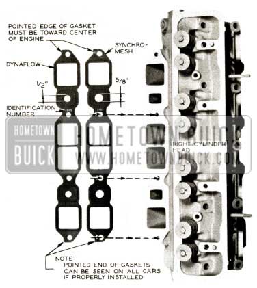
INTAKE MANIFOLD VACUUM LEAKS
We have received several product reports on intake manifold vacuum leaks on 1957 models. The causes for these leaks have been traced to the gaskets being installed improperly. The Dynaflow exhaust crossover hole in the gasket is 1/2” in diameter and the Synchromesh is 5/8 ”. These gaskets can also be identified by a number stamped on the gasket. See Figure 33.
1957 Buick Intake Manifold
Gaskets must be installed with raised side up (contacting bottom of intake manifold) and with sharp pointed end of gasket in toward center of the engine. See Figure 33. NOTE: If gasket was installed properly, pointed end of gasket can be seen on all cars.
CHECKING CARBURETOR STARTER SWITCH TIMING
With the carburetor installed on the engine. The following procedure may be used on Dynaflow equipped cars (regardless make of carburetor) to determine whether the carburetor starter switch timing is within proper limits. On synchromesh equipped cars, the carburetor must be removed; the switch timing may then be checked according to the procedure in the 1956 Service Manual.
- Make certain that transmission is in Park position and that parking brake is applied.
- Back off throttle stop screw, rotate fast idle cam to slow idle position if necessary, and fully close throttle valve. Make certain that dash pot does not prevent full closing of throttle valve.
- With throttle valve fully closed, measure distance from diaphragm flange of dash pot to near edge of dash pot arm on throttle lever. See Figure 34.
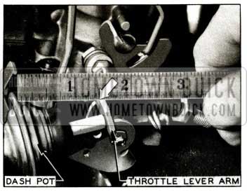
1957 Buick Starter Switch Timing
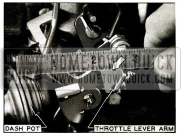
1957 Buick Starter Switch Timing Check
Carburetor – Difference
Carter – 2 Bbl. – 5/8 to 15/16
Carter – 4 Bbl. – 3/8 to 11/16
Stromberg – 2 Bbl. – 13/16 to 1 3/16
Rochester – 4 Bbl. – 1/2 to 3/4
- If necessary, retime switch by changing the number of timing shims as described in the 1956 Service Manual. When switch is correctly timed set engine idle speed at 485 RPM when hot.
CHOKE STICKING OPEN
1957 Carter Carburetor 4-Barrel
We have been advised by our Engineering Department that some difficulty has been experienced in the choke linkage on Carter 4-barrel carburetor equipped 1957 cars. The difficulty occurs when the air cleaner silencer is screwed down into position, causing it to interfere with the choke linkage, holding choke open, the after effect of which would result in hard starting.
This condition may be corrected by installing new air cleaner to carburetor gasket Gr.3.413 Part # 1458911. This will raise the air cleaner silencer assembly a sufficient amount to eliminate the binding condition.
ROUTING OF FUEL LINES
1957 Models
A few reports of the rubber fuel line rubbing against the engine fan belt on 1957 cars has been attributed to improper routing of the fuel line. This fuel line should be routed behind the generator mounting bracket and installed in clip on generator bracket. On air conditioner equipped cars the line should be behind the compressor mounting bracket, between the front compressor bracket brace and water manifold.
It is suggested that the service man check this fuel line on all jobs for proper routing whenever the car is brought in for service.
SHORT VACUUM LINE HOSE
1957 – All Series
Some reports have been received stating that the .vacuum line hose used between the Vacuum Pump Line and t-he windshield wiper motor, is too short, causing it to pull loose from the wiper motor. This hose has recently been changed from 19-1/2 to 20-1/2 inches long in production to reduce the possibility of it pulling off.
It is recommended that this hose be checked to make certain that it is pushed all the way onto the wiper motor connection when cars come in for lubrication or other service work. If it is apparent that the hose is too short, (that is, no slack in the hose) when fully seated at the wiper motor, then a new length cut to 20-1/2 inches should be installed. This hose is available in 50 foot rolls under Gr. 8.962 Part 601607.
IMPROVED FUEL ECONOMY
Engineering has released for service a new vacuum control diaphragm spring Gr. 2.416 Part #1921119 as a replacement for the #1930435 spring which was used with all 1956 distributors.
The new #1921119 spring will permit the vacuum advance mechanism to operate at a lower engine RPM, and it has been installed on several 1956 Buicks, with a slight improvement noted in both low speed economy and performance. It is suggested whenever the new vacuum control spring is installed that the vacuum advance unit be painted with a daub of green paint for identification purposes, since installation of the new spring will change the vacuum advance curve and it will indicate to anyone checking a distributor on a synchroscope that this change was made.
Flat Rate time for installing the vacuum control spring is .3 hr.
IDLE VACUUM
1957 Buick Engines
Idle vacuum values on all 1957 Buick engines (Dynaflow and Synchromesh) should be 14.5 min. inches of mercury with engine idling at 485 R.P.M. This is lower than past models and is caused by engine design and does not indicate failure of valves, Therefore, if engine is free of vacuum leaks, reconditioning of cylinder heads is unnecessary unless idle vacuum is belowl4.5 inches of mercury.
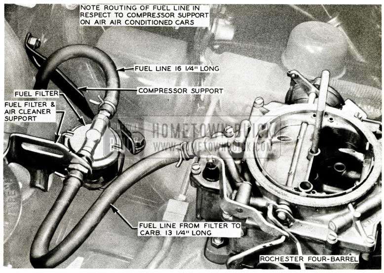
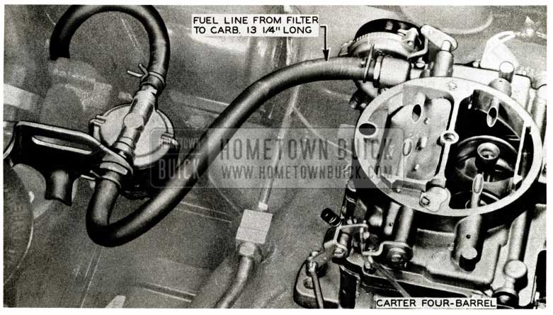
GLASS BOWL FUEL FILTER
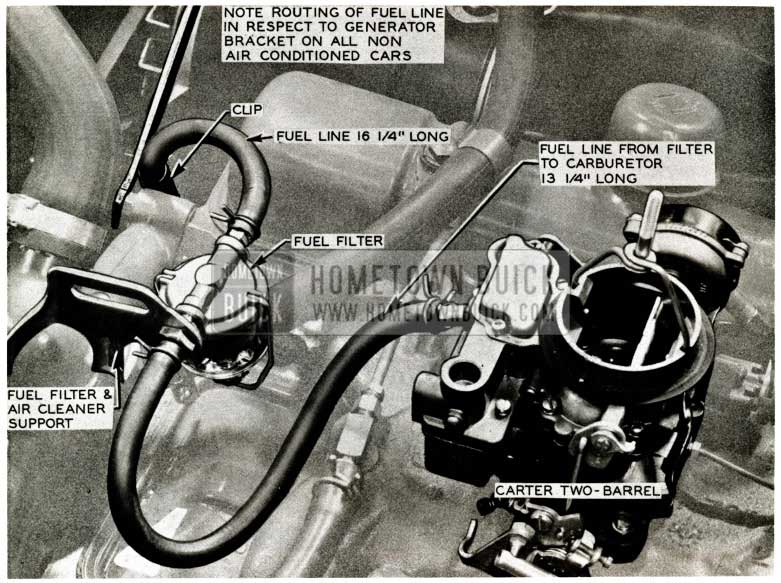
Engines bearing Manufacturing Code Numbers 237020 to 243399 inclusive and all those later than 24 7425 will be equipped with a glass bowl type fuel filter which is mounted on a support attached to the thermostat housing. See Figures 36, 37, 38, & 39.
1957 Buick Fuel Line Length
1957 Buick Fuel Line
1957 Buick Fuel Filter
1957 Buick Fuel Filter Line
The use of the glass bowl type filter will facilitate visual inspection in determining whether or not cleaning is necessary without having to remove parts as was required with first type filter mounted in the fuel tank. Ultimately, the tank mounted filter will be eliminated in production; however, the tank mounted filter will still be available from the Parts Department for 1st type j b.
The Parts Department advises that a glass bowl filter package Gr. 3.203 Part #1388170 which contains the following parts is being made available for sale to owners who want this type of filter installed. The package will consist of the following:
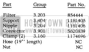
1957 Buick Glass Bowl Fuel Filter Parts
AFA’s will not be accepted for the installation of this package on jobs not equipped with glass bowl filters as they are already equipped with a tank filter; however, on unusual low mileage complaint jobs the filter package may be installed and AFA’d only by obtaining Zone authorization.
The inlet and outlet sides of the filter are clearly identified on metal casting; therefore, care should be taken so that it is positioned properly on the support mounted on thermostat housing. When assembling the filter, the connector should be installed on the outlet side with the nipple at the inlet. The assembly may then be mounted on the support and retained by the nut threaded on connector.
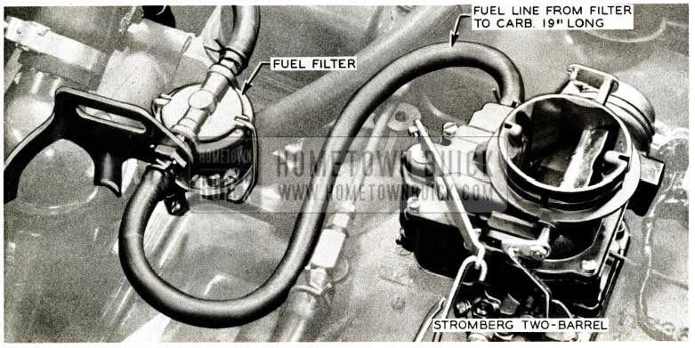
The proper length of hose from the fuel pump to the filter on all jobs is approximately 16 1/4 inches to be cut from existing hose on the car. The hose between the carburetor and glass bow1 filter is 13 1/4 inches on all jobs except those equipped with Stromberg Carburetors which require a 19 inch length. Cut hose furnished in package to specified length when the filter package is used.
Flat rate time for installing this package is .5 hr.
THROTTLE LEVER CAMPAIGN
1957 CARTER 4-BARREL CARBURETOR
Following is a reprint of Special Service Letter Dealer No. 210 dated May 2, 1957:
In the very near future each dealer will be receiving from the Zone Office, I.B.M. car record cards bearing serial numbers of cars that are to be called in, inspected and, if necessary, campaigned. Some of these cars will be equipped with Rochester carburetors and some with Carter 4- barrel carburetors. Only Carter 4-barrel carburetors are involved in this campaign, and nothing need be done with the Rochester equipped cars.
Listed below by Assembly Plants are serial numbers of cars that should be checked and, if necessary, campaigned:
Flint – D1063500 to D1103408 incl.
South Gate – D2019025 to D2030232 incl.
Linden – D3022108 to D3034464 incl.
Kansas City – D4020079 to D4032791 incl.
Wilmington – D5019016 to D5028988 incl.
Atlanta – D6017128 to D6029112 incl.
Framingham – D7006519 to D7012894 incl.
Arlington – D8013225 to D8022198 incl.
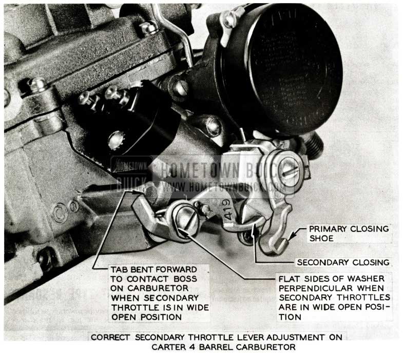
If the car is equipped with a Carter carburetor and the secondary throttle lever has the number “419” stamped on it, adjust this lever as follows: Levers not stamped ” 419” do not require adjustment
- Remove air cleaner.
- Hold choke in wide open position.
- Rotate secondary throttle valves to wide open position (with flats on secondary lever retaining washer perpendicular). Then bend secondary throttle lever tang until it just contacts the throttle stop. See Figure 40.
1957 Buick Secondary Throttle Lever Adjustment
1957 Buick Secondary Throttle Lever Adjustment Schematic
It will be necessary to bend the tang approximately 5/16″ to obtain proper adjustment and insure that the lever will be against the stop when the throttle valves reach the wide open (vertical) position.
Flat rate time allowed to perform this adjustment with the carburetor on the car is .2 hr. and includes R&R air cleaner.
The car record card should be attached to corresponding A FA for each car campaigned. If the car checked is equipped with a Rochester carburetor, return the card to the Zone Office with a notation on it to the effect that it had a Rochester carburetor. AFA’s will not be accepted for cars equipped with Rochester carburetors as they are not involved in this campaign and do not require any adjustment.
Whenever installing a 1957 Carter 4-barrel carburetor taken out of stock and it has the “419” secondary throttle lever, or whenever installing Modification Kit, Gr. 3. 725, Part #1181392 (covered in BPS 2.421, Page 22), the secondary throttle lever should be adjusted as mentioned above.
In addition, your AFA files should be reviewed and a list compiled of owners who already have had the Carter Carburetor Modification Kit 1181392 installed. These cars are to be campaigned also. A newly designed secondary throttle lever Gr. 3.759 Part #1182487, (Carter No. 53-A-430), has gone into production starting with carburetor code number E 7.
This new lever is included in Modification Kit, Gr. 3.725 Part #1182454, which will replace Kit 1181392 in the very near future. At that time, all existing orders for Kit 1181392 will be filled by Kit 1182454.
Stock of Kit 1181392 will continue to be used until exhausted; however, as previously mentioned, the tang on the secondary throttle lever should be adjusted as shown in Figure 10.
Your cooperation in concluding this campaign at the earliest possible date will be appreciated.
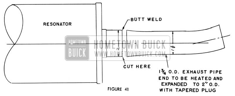
REWORKING FIRST TYPE RESONATOR
The first type resonator may be reworked as follows: Cut the resonator outlet off just to the rear of the resonator header. See Figure 41. The length of the 1 3/4 inch O.D. pipe is then welded to the header with a butt weld. The length of this pipe is determined by the length necessary to have this outlet extend 1/2 to 1 inch into the tail pipe extension in the bumper while maintaining proper clearance and location. The 1 3/4 inch O.D. resonator outlets may be made from 1956 dual exhaust tail pipes. (Approximately three outlets may be made from one pipe). The outlets, when welded to the resonator, must physically match the outlets removed, bend included. Pinch the lower metal bracket of the rear hanger together until it fits the 1 3/4 inch O.D. pipe. With the use of these smaller outlets, it will be necessary to use 1956 tail pipe clamp Gr. 3.705 Part #1170325.
NOTE: It is important, when reassembling the resonator into the car to position the outlet so that it is centered into the tail pipe extension and that the rear bumper is not grounded on the body or the tail pipe.
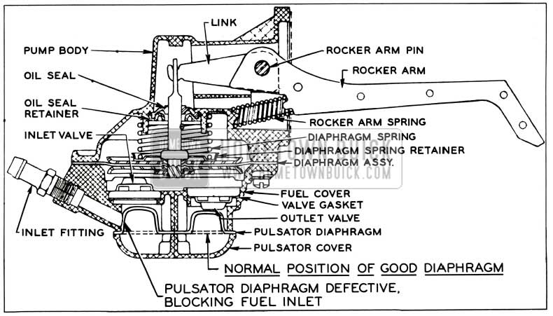
FUEL PUMP DIAPHRAGM CHANGE
We have been advised by Engineering that some engines built after March 4th may be equipped with a fuel pump which has a pulsator diaphragm made of interior material which is not compatible with gasoline. When the engine becomes hot, the gasoline causes the pulsator diaphragm to swell to a point where it stretches far enough to completely block off the inlet side of the pump. See Figure 42.
1957 Buick Magnesium Diaphragm
1957 Buick Fuel Pump Vacuum Unit
When this happens, it starves the engine, preventing it from running.
Whenever a complaint is encountered where the engine will not start, disconnect the fuel line from outlet side of pump and momentarily crank engine with shift control lever in park position on Dynaflow jobs and neutral on Synchromesh jobs. If fuel is not discharged from pump outlet and it is known that fuel line to the pump is okay and the gas tank is not empty, the pump should be removed and a new diaphragm, Gr. 3.925 Part #5621088, installed.
MAGNESIUM DIAPHRAGM COVER
1957 FUEL PUMP
Following is a reprint of Special Service Letter – Dealer No. 220 dated August 7, 1957:
We have been advised by our Inspection Department that most engines built between Manufacturing Code No. 241715 to 331332 will eventually result in fuel pump pulsator diaphragm failures. The pump on these engines is of the early type which is equipped with zinc pulsator diaphragm cover. Ordinarily, these engines would be campaigned in the field and the new magnesium cover, Gr. 3.901 Part #5621162, and diaphragm, Gr. 3.925 Part #5621088, installed. Unfortunately, however, Production’s records do not indicate the serial number of cars in which these engines were installed. Therefore, it is impossible to conduct such a campaign.
It is requested, however, that dealer service men check all 1957 cars that come in for service and observe the engine Manufacturing Code Number to see if it falls within the range of those listed above. If the code number indicates that the engine may be equipped with a fuel pump having a zinc pulsator cover, inspect fuel pump from underneath car while it is on lubrication rack or place a mirror underneath pulsator cover to see if very small letter “o” is stamped between letters ” AC”. Letter ”o ‘ ‘ indicates cover is made of magnesium and it is the very latest type which could have been installed before the car left the Assembly Plant or by another dealer. If this is the case, nothing need be done except to apply a daub of yellow paint on the top of the pump which will indicate to anyone visually inspecting it that it is of the latest type.
If the pump is found to be minus the letter “o” then it has the first type cover (zinc) in which case the cover and diaphragm should be replaced with the magnesium cover, Gr. 3.901 Part #5621162, and new diaphragm, Gr. 3.925 Part #5621088. After installing these new parts, apply a yellow daub of paint to the top of the pump body, the purpose of which is explained above.
Flat rate time for installing the magnesium cover and new diaphragm is .5 hr., which includes R&R pump and applying yellow daub of paint on pump body.
Leave A Comment
You must be logged in to post a comment.