RUN-DOWN BATTERIES
A few cases of run-down batteries have been found to be due to improper adjustment of the trunk light which allows the light to remain on when the lid is closed.
When properly adjusted, the trunk lamp should light when opening the trunk lid, at a point from eight (8) to ten (10) inches before the lid is fully open. If the light does not come on at this point, bend the lamp assembly bracket forward until the mercury switch makes contact and lights the bulb. Conversely, if the bulb lights at a point before the lid is raised to the above described height, the bracket should be bent rearward.
STOP LIGHT SWITCH REMOVAL
We have received reports that stop light switches Gr. 2.447 Part number 1328118 (1941-55) and ll71472 (1956-57) are so machined that there isn’t a socket available that will fit them. This is to advise that a one (1) inch 6-point socket will work satisfactorily; however, a 12-point socket in the same size will not.
SPARK PLUG WIRE REMOVAL
1957
It has been brought to our attention that it is possible to damage spark plug wires on 1957 Models due to car less method of disconnecting the wires from the spark plugs.
Since the 1957 resistance type spark plug wires have a linen core impregnated with carbon, pulling carelessly on the wire can cause cracking or separation of the core, causing excessively high resistance and possible engine missing. It is, therefore, very important to instruct your service personnel to grasp the spark plug wiring by the boot whenever they are removed instead of by the wire.
It has also been brought to our attention that mechanics, when timing an engine, insert an ice pick through the number one (1) spark plug wiring insulation. This practice should be discontinued, for it will damage the wire. The regular spark plug adapter used with tune-up equipment may be used between the plug and wire, and the timing light lead may be attached directly to the adapter.
DISTRIBUTOR SPECIFICATION
1957 MODELS
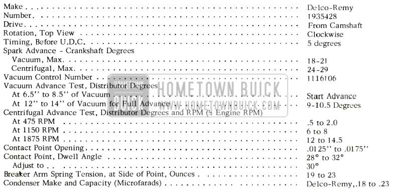
1957 Buick Distributor Specification
SPARK PLUG INFO.
The vast amount of research, development, and testing of the AC -44 spark plug by Buick has led us to use it as standard equipment as its heat range and performance is ideal for use in Buick V- 8 engines.
The proper heat range spark plug is very important in controlling pre – ignition and fouling. When too high a heat range spark plug is used in the Buick engine and the car is driven for extended periods at highway speeds, it is possible to encounter pre-ignition which may result in burned pistons. When too cold a heat range is used, spark plugs may foul resulting in poor engine performance at low speeds. The cost of repairs then becomes owner responsibility as Factory warranty would not be applicable.
The Engineering Department recommends the AC-44 heat range spark plug for use in Buick V – 8 engines except for prolonged high speed driving, in which case they recommend the AC-42 Commercial heat range spark plug.
Service experience with the AC -44 spark plug bears out the fact that a minimum of difficulty has been encountered over the years. It is for this reason that plans are to continue its use as standard equipment in order to provide Buick owners with proper performance and product protection.
NOISY STARTER
1957
We have been notified by Engineering that a few engines between production code numbers 0-8500 and 10000 to 11000 were equipped with blocks having the cranking motor hole approximately .015″ off location, toward the centerline of the crankshaft. Consequently, when starting an engine having this condition, a screeching sound would be heard as a result of the tight fit between cranking motor drive gear and ring gear.
It is felt that all engines having this condition were repaired before leaving the assembly plants; however, we are bringing this item to your attention in the event a few escaped inspection.
The only corrective measure to repair an engine having this condition is to replace the block.
If and when it should become necessary to replace a cranking motor on a 1957 engine, it is suggested that during installation the cranking motor be positioned away from center line of engine as far as possible. The reason for this is that some engines that had cranking motor hole in block off location as mentioned above were repaired at the factory by elongating the hole with special equipment. Therefore, if a cranking motor replacement is made on one of these engines, it is important to make the installation as described above, otherwise, a noisy starter will result.
DISTRIBUTOR SHAFT END PLAY
Dealers have been overhauling 1957 distributors unnecessarily to correct so-called excessive end play.
The distributors used in 1957 are designed to have .036 to .068 inch end play. This end play is necessary due to the construction of the distributor. If the end play is removed, it will cause friction between the circuit breaker cam and the top of the circuit breaker plate or bearing. This will affect ignition timing.
When the car engine is turning over, the thrust of the distributor gear is always up. The end play permits the circuit breaker cam to raise off from the circuit breaker plate or bearing. Since the thrust is always up and the engine is timed with the engine running, the end play has no effect on spark timing. It is important that the shaft be pushed up when the distributor advance is checked on a test stand.
GENERATOR FAILURES
1957
A recent investigation revealed that the cause of most 1957 generator failures has been attributed to premature wear of the bushing in the commutator end frame which is a result of lack of lubrication.
Due to the increase in operating speeds, increase in belt tension and generally higher electrical loads, there is more pressure against this bushing and unless sufficient oil is available rapid wear usually results. Therefore, dealer service (Lubricare) men should place special emphasis on this item to properly lubricate the generator as follows: Fill front and rear oilers to the caps with light engine oil. Wipe off excess or spilled oil. Never lubricate the commutator and do not lubricate generator while it is operating. If oil reserve in commutator end bearing is exhausted due to failure to lubricate at proper intervals, the rear oil cup should be filled three (3) times, allowing time for each filling to soak down.
SETTING IGNITION TIMING
Following is a reprint of Special Red Band Service Letter, Dealer No. 191, dated November 14, 19S6.
We have received dealer Product Reports stating that difficulty is being encountered in setting ignition timing on 19S7 engines, and that some jobs are reported to have a hesitation or stumble on acceleration. Other reports indicate general lack of performance.
Engineering advises that the above conditions can result if the proper procedure is not followed when timing 19S7 engines. The proper timing procedure is as follows:
- Disconnect the vacuum advance line to distributor either at carburetor or distributor.
- Set engine idle at less than 400 R .P.M. (Never exceed 400 R.P.M.).
Steps 1 and 2 will insure that both the vacuum advance and centrifugal advance units are not in operation when performing Step 3.
- Using timing light, set timing so before top dead center.
- Reconnect vacuum advance line and adjust idle speed to 48S R .P.M. with transmission in Neutral or Park.
When the above steps are completed, it will be noted that the timing mark on harmonic balancer will be advanced beyond the S0 mark a considerable amount because both the centrifugal and vacuum units may be in operation.
In order to improve economy at low speeds, the vacuum advance on 19S7 models comes in earlier and is greater than on 19S6 models. Because of this, it is impossible to properly set timing in excess of 400 R .P.M. and with vacuum line connected.
SPARK PLUG WARRANTY
As pointed out in the Buick Service Policy Administration Manual, any spark plug found defective in Buick engines within the warranty may be returned to AC Spark Plug Division for replacement. After AC Spark Plug Division has determined to their satisfaction that the plug is defective, an exchange slip for all such plugs will be issued to the dealer. The exchange slip may be redeemed for an equal number of new spark plugs on a no cost basis at the Buick Motor or through any AC distributor. All a dealer has to do is to countersign the exchange slip and forward it to the warehouse with an order for the type of plug desired. The Buick warehouse will then ship the required number of plugs to the dealer, no charge. Dealers should keep in mind when returning spark plugs to AC for credit that they will receive credit only for defective plugs. Dirty or burned plugs due to improper ignition adjustment will not be credited. Due to the high heat of the spark plug insulator under severe driving conditions, the spark plug boot tends to harden and crack after use. In this hardened condition, they no longer control the ignition voltage and missing may result, even if new plugs have been installed. For this reason, it is recommended to inspect boot for hardness or cracking and replace if necessary whenever new plugs are installed. Doing so will help eliminate needless replacement of plugs. Sometimes plugs are replaced along with points and a motor tune-up when actually there is nothing wrong with the plugs and they would have given satisfactory service if they had not been removed. Naturally, in such cases AC Spark Plug Division will refuse credit.
HEADLAMP TO FENDER ATTACHMENT CHANGE
1957 Models
A recent change has been made in production in the attachment of the headlamp to the front fender. This change consisted of removing the Spring Nut, Group 8.921 Part 1173116, which fits over the front fender headlamp opening flange and retains the head lamp to front fender screw. When this nut was removed, the 17/64 inch headlamp screw clearance holes in the front fender headlamp opening flange were removed and replaced by S /32 inch extruded holes in the same locations. At the time this change was made, the original headlamp retaining screws were replaced by a new hex head washer face headlamp retaining screw, Group 8.977 Part 416194. The original spring nut will remain released for past model and 19S7 first-jobs service use. No part number change was made to the front fenders as either type can be used by using the appropriate attaching parts.
LIGHT SWITCH CHANGE
1957 Model
In order to provide more clearance between the 19S7 Light Switch, Group 2.48S Part 199S079, and the Speedometer, to facilitate assembly of the Safety Minder Reset Shaft to the Speedometer Housing, the Light Switch positioning hole has been relocated. With this new positioning hole, the Light Switch is rotated sufficiently to prevent the possibility of the Speed Safety Minder Cable binding.
First service shipments of this Light Switch, 1995079, will have the positioning hole in the old location. When installing one of these Light Switches on a car equipped with Safety Minder Speedometer, it will be necessary to drill a new positioning hole as shown in Figure 98.
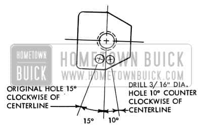
1957 Buick Light Switch Positioning Hole
DEAD SPOT IN HORN RING
1957 MODELS
There have been numerous complaints stating that there were dead spots in the horn whereby when the horn ring is depressed the horn will not operate. This difficulty may be overcome by adding a special spacer washer, Gr. 2.823 Part #1181441, between the steering wheel hub and the lower horn contact. See Fig.99.
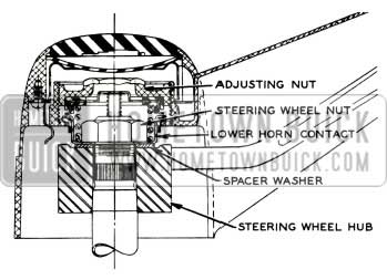
1957 Buick Horn Ring
When the spacer washer is added it will provide additional clearance between the horn ring and the steering wheel giving more travel to the horn ring making it less critical to obtain a satisfactory adjustment.
The above change went into production approximately March 1st, however, sometime in the near future the steering wheel hub will be modified to give added clearance between the horn ring and the steering wheel. These “after-job” hubs will be identified with a + stamped on the top side of the hub. CAUTION: The washer must not be used on jobs having the modified steering wheel hub or there may not be sufficient threads on the steering shaft for the steering wheel nut to lock.
When horn ring adjustment is required on first jobs, install the spacer washer between the steering wheel hub and the horn contact spacer. The contact opening can then be properly adjusted by turning the adjusting nut until the contacts are completely closed and then backing the nut off from 3/8 to 1/2 turn.
When the washer, Gr. 2.823 Part #11814 1. is installed it is important that the steering wheel nut be tightened to 30 to 35 ft. lbs. of torque and that sufficient thread contact exists to insure locking action of nut.
BROKEN SAFETY SWITCH
Dealer product reports have been received stating that they have encountered a few early production 1957 cars with broken Neutral safety switches. These switches were improperly adjusted during assembly causing them to bind in either Park or Reverse. This condition has been corrected in production. Therefore, whenever a new switch is installed, it is important that the following procedure for correct adjustment be followed:
- Check Dynaflow control linkage and adjust if necessary.
- Place shift control lever in Neutral position.
- Insert a 3/32″ drill or a piece of 3/32″ drill rod through gauging hole in operating lever and into gauging hole in switch body. See Figure 100.
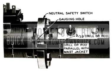
1957 Buick Safety Switch Repair
CAUTION: Be careful not to cause shift control lever to move out of Neutral position.
LOOSE WIRING HARNESS PLUG
1957 Models
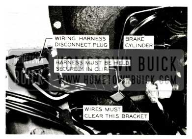
Several reports have been received regarding inoperative headlights which has been traced to a loose connection of the chassis wiring harness to the harness disconnect plug on the cowl. It is, therefore, suggested when performing new car inspection and again at 1,000 mile inspection to check these connections. The grommet should be properly positioned in the cowl, and engine compartment section of the harness should have the spade terminals fully seated to the disconnect plug. The harness should be properly routed through clips on the left ventilator air duct cover (blister) with clip tight to the harness so that the harness will not contact the spark plug wire bracket as shown in Figure 101.
1957 Buick Short in Wiring Harness Repair
SHORT IN WIRING HARNESS
1957
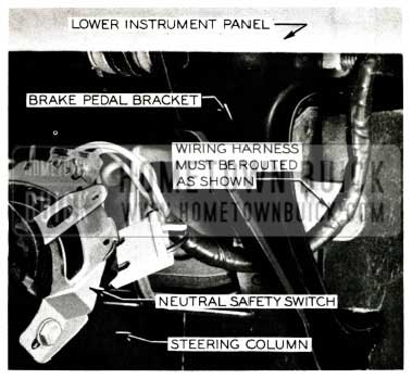
We have received several product reports stating that a short in the wiring harness exists due to the harness being caught between the brake pedal arm and pedal bracket. The wiring harness should be routed as shown in Figure102 to prevent wire shorting in this area.
1957 Buick Short in Wiring Harness
Another cause for wiring harness shorting has been traced to the radio condenser and bracket assembly at the voltage regulator being installed upside down , allowing it to contact the battery junction block or ignition switch wire . If condenser is installed properly, the bracket will prevent it from rotating when attaching bolt is tightened.
SAFETY-MINDER SERVICE INFORMATION
TROUBLE-SHOOTING SAFETY -MINDER
The Safety-Minder is standard equipment on Series 70 and is a factory installed option on all other series. This feature consists of a buzzer which may be adjusted by the driver to sound at any speed between 20 and 110 MPH by turning a knob on the lower instrument panel. The speed at which the Safety-Minder is set is indicated by a dial in the lower left corner of the speedometer face.
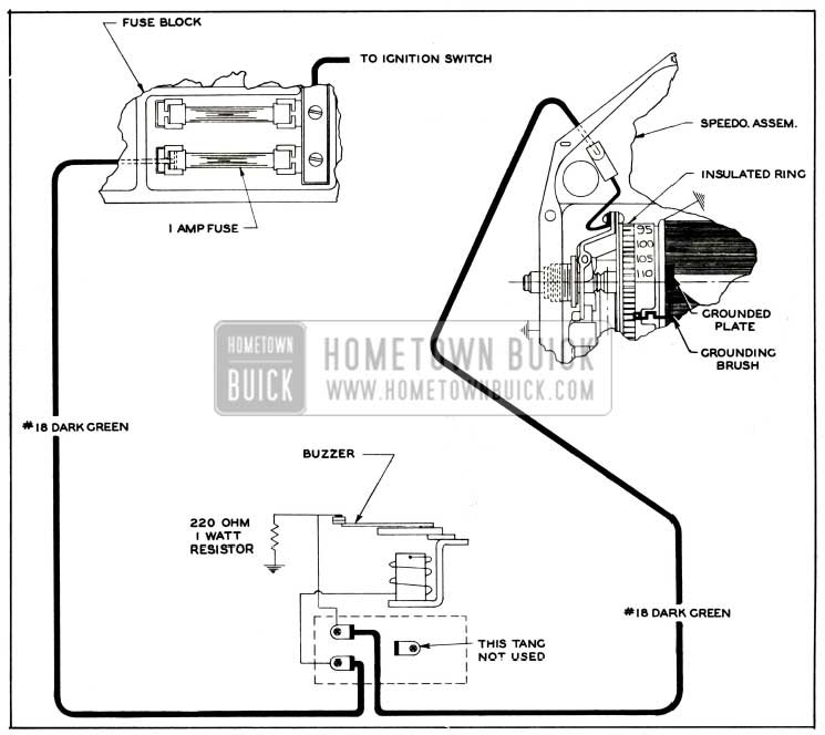
The Safety-Minder electrical circuit starts at a 1 ampere fuse marked ”ACC”, located on the fuse block. See Figure 103.
1957 Buick Safety Minder
This circuit is “hot” whenever the ignition switch is turned on. From the fuse, a dark green wire carries the current to a buzzer mounted on the left ventilator air deflector. After passing through the buzzer contacts, a very small amount of current goes through a resistor to ground and the rest of the current passes through a second dark green wire to a connector on the speedometer case.
In the speedometer, current is conducted to an insulated ring which has a dial reading from 20 to 110. A grounding brush projects from this insulated ring in such a position that a grounded plate on the speedometer cylinder will contact it as the cylinder rotates, thereby grounding the circuit and causing the buzzer to operate.
The insulated ring with its dial and grounding brush can be rotated by turning the reset knob while observing the dial through a small window in the lower left corner of the speedometer. The car will then have to be moving at the rate of speed indicated on this dial before the speedometer cylinder will rotate far enough for its grounded plate to contact the brush.
BUZZER WILL NOT OPERATE OR OPERATES INTERMITTENTLY
- Disconnect buzzer circuit at speedometer. To get at this connector, slip fuse block down and reach up with left hand between fuse block brackets and forward of heater duct to upper left corner of speedometer. Feel location of connector to make replacement easier. Then remove connector by sliding it sideways.
- To check complete buzzer circuit up to speedometer, ground this connector with ignition switch turned on. (For a convenient means of grounding, push a paper clip into connector). If buzzer now operates, circuit is O.K. and trouble must be in speedometer. Before removing speedometer, however, double check this by reinstalling connector on speedometer. Then jack up rear wheels and run speedometer up through speed set on Safety Minder.
- If buzzer did not operate when speedometer connector was grounded (in Step 2), trouble must be in buzzer circuit. Check fuse at “ACC” on fuse block and replace if necessary with a one ampere fuse.
- Check buzzer circuit wiring connectors at fuse block, buzzer, and speedometer. See Figure 103.
- Next eliminate buzzer as source of trouble by unplugging connector at buzzer which is mounted on left ventilator air deflector. Then plug a known good buzzer onto the connector. There is no need to ground buzzer – just let it hang from connector.
BUZZER OPERATES CONTINUOUSLY
- Check dark green wire from buzzer to speedometer for ground.
- Disconnect wire at speedometer as described in Step 1 above. If buzzer stops, circuit is grounded inside speedometer and speedometer must be removed for repair. If buzzer still operates, however, buzzer unit is defective and must be replaced.
RESET SHAFT BINDS
- Check knob for interference with instrument panel. Relieve if necessary.
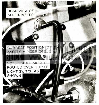
- Check routing of reset shaft. Must route “over” light switch instead of between light switch and speedometer. See Figure 104 for correct routing.
1957 Buick Safety Minder Cable
SPEEDOMETER STICKS
- Check to see that buzzer is latest type having a resistor. This can be identified by a pig-tail welded to the mounting base. Replace buzzer if it is not of the latest type.
- If above does not correct, send speedometer assembly to the nearest UMS Service Station for repairs.
Leave A Comment
You must be logged in to post a comment.