PEDAL RETURN SPRING CAMPAIGN
1957 Power Brake
Following is a reprint of Special Service Letter – Dealer No. 211, dated May 8, 1957:
In Special Service Letter – Dealer No. 209, dated April 26th, it was announced that the torsional power brake pedal return spring was being replaced by the extension type return spring. On some of the very first jobs, so equipped, this new spring was mounted as shown in Figure 94.
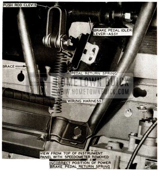
1957 Buick Brake Pedal Return Spring
Because of the possibility of interference between wiring harness and spring when mounted as shown in Figure 94, it is requested that those cars so equipped be campaigned and the spring relocated as shown in Figure 95.
1957 Buick Brake Pedal Return Spring View
Only power brake equipped cars built by the following assembly plants are involved, and cars having serial numbers which fall within the range of those listed are to be campaigned:
Flint – 1089221 to 1097108 incl.
South Gate – 2027426 to 2028560 incl.
Linden – 3030249 to 3032146 incl.
Framingham – 7011280 to 7012028 incl.
In the very near future, those dealers affected will receive from the Zone Office, I.B.M. car record cards bearing serial numbers of cars to be campaigned.
When these cars are received at the dealership, perform the following operations:
- Disconnect negative battery cable and wiring from neutral safety switch.
- Remove spring from location shown in Fig.94.
- Remove push rod to brake pedal lever clevis pin.
- Remove clevis from power cylinder push rod. NOTE: Hold push rod with vise grips or pliers to prevent rod from turning.
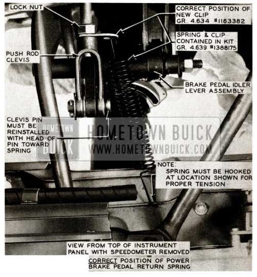
- Install new clip, Gr. 4.634 Part No. 1163382, on power cylinder push rod and reinstall clevis as shown in Figure 95.
- Before reinstalling push rod clevis pin, operate pedal by hand to make certain the linkage operates freely.
- Reinstall push rod clevis pin and spring as shown in Fig.95. NOTE: The head of the clevis pin n1ust be toward the spring to prevent cotter pin interfering with spring.
- Check pedal height by placing ruler at left of pedal rubber pad midway between top and bottom perpendicular to toe pan. With ruler pressed firmly against floor mat, distance from toe pan to top of rubber pad should be 5 1/2″ as shown in Fig. 4 of BPS 2.419, Page 87.
- If pedal height is not correct, ad just push rod as required to obtain proper pedal height position.
- Reconnect battery cable and wiring to neutral safety switch.
The flat rate time to complete this campaign is .5 hour.
Please note on some of the cars built at the Flint and Linden assembly plants the very first jobs equipped with the lighter pedal return spring at the end of the push rod also were inadvertently equipped with the torsional brake pedal return spring; therefore, dealers receiving cars from both of these plants should check for the installation of both pedal return springs and should also remove the torsional spring before relocating new spring at end of push rod. To remove the torsional spring and correctly position the extension type spring, proceed as follows:
- Disconnect negative battery cable and wiring from neutral safety switch.
- Disconnect bowden wire from clip at left dash ventilator.
- Remove screw holding dash insulator to cowl to facilitate removal of upper left brake pedal mounting bracket to cowl attaching bolt.
- Remove upper left brake pedal mounting bracket-to-cowl attaching bolt so that the 6-3/4″ bolt on which the pedal is mounted may be removed. On 1957 after-jobs, a stud replaced the upper left brake pedal mounting bracket-to-cowl attaching bolt. This was done to facilitate better assembly in production. Therefore, on jobs equipped with the stud it will be necessary to first remove nut from this stud and loosen the other three (3) pedal mounting bracket-to-cowl attaching bolts so that the pedal mounting bracket assembly may be pulled away from the cowl and the 6-3/4″ bolt removed without interference from this stud.
- Remove push rod to brake pedal lever clevis pin.
- Using a suitable tool, work torsional pedal return spring off brake pedal and discard; then install and securely tighten the 6-3/4″ pedal mounting bolt.
- Using wrench 6618, make sure that the large nut holding power brake unit to cowl is firmly tightened ; then reinstall the three (3) pedal mounting bracket-to-cowl attaching bolts and nut on stud, making certain they are firmly tightened. Install dash insulator attaching screw removed in Step 3 above.
- Remove clevis from power cylinder push rod. NOTE: Hold push rod with vise grips or pliers to prevent rod from turning.
- Install clip, Part No. 1163382, onto power cylinder push rod and reinstall clevis as shown in Figure 95.
- Before reinstalling push rod clevis pin, operate pedal by hand to make certain the linkage operates freely.
- Lubricate push rod clevis pin with Lubriplate; then reinstall pin and spring as shown in Fig. 95. NOTE: The head of the clevis pin must be toward the spring to prevent cotter pin from interfering with spring.
- Check pedal height by placing ruler at left of pedal rubber pad midway between top and- bottom perpendicular to toe pan. With ruler pressed firmly against floor mat, distance from mat to top of rubber pad should be 5 1/2″ as shown in Fig. 4 of BPS 2.419, Page 87.
- If pedal height is not correct, ad just push rod as required to obtain proper pedal height position.
- Reconnect battery cable and wiring to neutral safety switch.
The flat rate time to complete this campaign on jobs equipped with both torsional and new return spring is 1.7 hour.
Please attach the I.B.M. car record card to corresponding AFA for each job campaigned.
NOTE: Approximately April 22nd, production started using power brake cylinders having a heavier internal valve return spring which eliminates the need for the extension type return spring. Therefore, all power brake cylinders, identified with a daub of green paint on hydraulic cylinder casting will not have any external type of pedal return spring on the pedal linkage. This applies to both Moraine and Bendix units.
NEW FRONT BRAKE HOSE
All Models 75
We have been advised that the front brake hose on 1957 Models 75, 75R and 76C are being changed to a shorter length hose.
The new hose, Gr. 4.680, Part#1182856, is one inch shorter or 10 1/8” long and can be readily identified by a daub of red paint on the hose fitting. The first type brake hose, Gr. 4.680, Part #1174175, which is 11 1/8″ long will still be used on all other models.
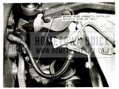
When installing either hose, care must be exercised to prevent a twist in the hose. A twist may cause the hose to kink and touch the frame or brake assembly during front wheel movement with consequent rub-through and ultimate brake failure. An undesirable twist can result from failure to hold the hose fitting at the frame bracket when the nut on the brake pipe assembly is tightened. Figure 96 shows a brake hose correctly installed.
1957 Buick Front Brake Hose
NOTE: The correct length hose must always be used on the proper model.
POWER BRAKE SERVICE INFO.
REMOVAL, INSTALLATION, ADJUSTING, TESTING OF POWER BRAKE UNITS
The same procedure is used for removing, installing, adjusting, or testing either the Moraine or the Bendix power brake unit. Operation, disassembly and assembly are different, however, and are covered in the Product School Manual.
Removal of Power Brake Unit
- Disconnect battery ground strap.
- Remove clevis pin from push rod clevis.
- Lift brake pedal to pull linkage out of the way, then remove large nut holding brake unit to cowl using Wrench 6618.
- Disconnect stop light wire connector from switch.
- Disconnect brake pipe from hydraulic cylinder and tape end of pipe to prevent entrance of dirt. Disconnect vacuum hoses from tee.
- Remove bolts holding unit to ventilation air duct and remove power brake unit from car.
- Remove filler cap and turn unit so that any brake fluid will drain out. Pump push rod by hand for full interior drainage. Discard old fluid. Install filler cap and cover hydraulic cylinder outlet with tape to exclude dirt. Clean all loose dirt from outside of unit before disassembling.
Installation of Power Brake Unit
- Position power brake unit in ventilation air duct and install bolts to hold unit to air duct.
- Connect brake pipe to hydraulic cylinder. Connect vacuum hoses to vacuum tee.
- Connect stop light wire connector to switch.
- Loosen brake reinforcing bracket bolt and nut.
- Lift brake pedal to pull linkage out of the way, then install and tighten large nut using Wrench 6618. After large nut is tight (30-40 ft. lbs.), tighten reinforcing bracket bolt and nut.
- Install spring washer, clevis pin, and cotter key in push rod clevis.
- Check brake pedal for correct height as described below (subpar. c). Adjust pedal height if necessary.
- Reconnect battery ground strap.
- Bleed hydraulic system in same manner as standard brake system. After bleeding bring fluid level to 1/4 inch below lowest point of bottom thread in filler opening. NOTE: When pressure bleeding equipment is not available, do not use any vacuum assist, the engine should not be running and the vacuum reserve should be used up by repeatedly applying the brake before starting the bleeding procedure.
Checking and Adjusting Brake Pedal Height
Correct pedal height is important to insure adequate pedal travel and to make sure that the pedal is in the proper position to get the best linkage action.
- Make certain that brake pedal returns completely when released slowly. If pedal does not return freely; check linkage for binding and check condition of pedal return spring.
- Place ruler at left of pedal rubber pad midway between top and bottom and perpendicular to toe pan. With ruler pressed firmly against floor mat, distance from toe pan to top of rubber pad should be 5 1/2 inches.
- If pedal height is incorrect, loosen push rod lock nut.
- Turn push rod as necessary to adjust pedal height to 5 inches.
- Hold push rod and tighten lock nut. Recheck pedal height.
- Start engine and depress brake pedal firmly. If pedal travels to within 1 inch of toeboard and has a hard feel, brake shoes require adjustment or relining. However, if pedal has a spongy feel, brake system needs bleeding.
Testing Power Brake Unit
- Vacuum Assist. With engine stopped, apply brakes several times until all vacuum reserve in system is used up. Then depress brake pedal and start engine while holding a light pedal pressure. If vacuum system is operating properly, pedal will tend to fall away from under the foot, and less foot pressure will be required to hold pedal in same position. If no action is felt, vacuum system is not functioning.
- Hydraulic Leak. Apply a heavy foot pressure on brake pedal with engine running. Hold this pressure at least 15 seconds and observe brake pedal. If pedal goes down gradually, check first for a leak in system outside of power brake unit. When possibility of an external leak is eliminated, leak is in hydraulic cylinder of power brake unit.
- Vacuum Leak. Allow engine to idle a minute to build-up vacuum reserve. Shut off engine and wait several minutes at least (system should hold vacuum for 12 hours) before trying brake action. If brake is not vacuum assisted for at least 4 slow applications there is a leak in the vacuum system. Always check for an external leak before blaming leak on power brake unit.
- Road Test. Apply brakes several times at about 20 m.p.h. to determine if a light pedal pressure stops the car evenly and quickly. Notice pedal feel as compared to other cars of the same model.
BRAKE DRUM SPEC. CHANGE
(1957 Models)
Drum diameter has been changed in production from 12.020 +or- .003 to l2.015 +or- .005 to decrease lining wear during initial break-in which previously resulted in early brake adjustments.
Also, a new heat treatment process in the manufacture of all Buick rear drums has been in production for some time which increased the hardness and greatly reduced scoring tendencies. These drums are identified by a letter “D” approximately one-half (1/2) inch high stamped on drum outer flange and may be observed when wheel is removed. If any drum scoring is encountered with these drums, please submit a Product Report and indicate that letter “D” was stamped on rear drum; also, include color code of brake linings with any other pertinent information available.
FILLING & BLEEDING BRAKE SYSTEM
1957 – All Series
It is imperative during the brake bleeding operation to make certain no brake fluid is carelessly spilled on the backing plates of either front or rear brakes, because of the danger of this fluid getting on the brake shoes through the backing plate and causing permanent damage to the lining with a consequent brake pull.
The fluid on the backing plate can enter around the wheel cylinder opening or at the sheet metal adjustment hole cover on both front and rear brakes. This condition is especially bad on finned aluminum drums, because any fluid on the edge of the drum where the cast iron and aluminum joint is open will be drawn into the seam by capillary action, and will come out on the drum surface around the pegs every time the drums become heated from braking.
BRAKE PEDAL LINKAGE CHANGE
A change has been made in the 1957 Brake Pedal Linkage on cars equipped with regular brakes to increase the clearance between the brake pedal arm and the brake linkage idler lever arm. This change consisted of rotating the arm on the brake pedal slightly and lengthening the brake linkage link which in turn increased the clearance between the arm on the brake pedal and the arm on the brake linkage idler lever.
If a new brake pedal was used with the old shorter link, the pedal pad would be improperly positioned. For this reason, the first and after jobs parts are not interchangeable. However, in order to provide the increased clearance, allowed with the new brake pedal, only the new brake pedal will be available for service replacement. When a brake pedal is replaced, it will be necessary to install a second type link. Both first and after jobs links will be available for service use. Following are the parts involved:
Group 4.625 – 1175222 Brake Pedal 1957-40 Synch.
To be replaced by:
Group 4.625 – 1180538 Brake Pedal
Group 4.625-1174296 Brake Pedal 1957 Dynaflow Regular Brakes
To be replaced by:
Group 4 .625 – 1180537 Brake Pedal
Group 4.632 – 1172806 Link-Brake Linkage 1957 Regular Brakes First Jobs
Group 4.632 – 1180536 Link-Brake Linkage 1957 Regular Brakes After Jobs
FLUID LEAK AT STOP LIGHT SWITCH
1957 Power Brake Cars
We have received a few reports of hydraulic bra e fluid leaking at the stoplight switch on 1957 power brake equipped cars.
If leaks of this type are encountered and the 15 lb. torque applied to the stoplight switch nut does not correct it, remove the switch and check the hydraulic cylinder housing for possible cracks. If housing is found cracked, return the hydraulic cylinder housing to your Zone MR Room, properly tagged giving all pertinent information.
It is further suggested that this stoplight switch location be checked for leaks at the new car make-ready and also at the 1000 mile inspection.
BRAKE FLUID CONTAMINATION
We have some reports from the field on brake system failures that were investigated and found to be caused by contamination of brake fluid.
The fluid had become contaminated through the use of a general purpose pump to pump both brake fluid and mineral oils from storage drums.
Extreme care must be exercised to avoid contamination of brake fluid since very small quantities of mineral oil which is used in transmissions and engines can cause the rubber components of the brake system to distort and swell if they are mixed with the fluid.
The following precautions must be taken when handling brake fluid.
- Do not store drums or containers of brake fluid with containers of mineral oils.
- Do not use a general purpose pump to pump brake fluid.
- Fluid withdrawn during bleeding operations should not be used again. Throw it away! Replenish supply tank or reservoir with new fluid.
- Never wash brake cylinders or parts in gasoline, kerosene, or oil. Dip parts in brake fluid before reassembling.
- Use ONLY G.M. No. 11 heavy duty brake fluid. Available at all Buick Warehouses under Gr. 4.683 in pint, quart, one gallon, five gallon can or 30 gallon drum.
BRAKE DRUM USAGE
The following is a reprint of Special Service Letter, Dealer No. 200 dated February 22, 1957.
Please note that the starting serial number for the Linden Assembly Plant has been corrected to show that 40 Series Synchromesh built cars started using the Motor Wheel Drum with Serial #D3024057 where as Serial #D3022514 and D3023391 are for Dynaflow cars.
Starting approximately February 4th Motor Wheel brake drums are being used in production at the front end of all jobs. These new drums are shown in Figure 97, which compares them with Buick production drums used on first jobs. By observing the differences in construction between the Motor Wheel drum and that of the Buick drum, one can easily establish their identity. You will note that the circumferential rib in the series 40-50-60 Motor Wheel drums is narrower than that of the same make used on series 70 models.
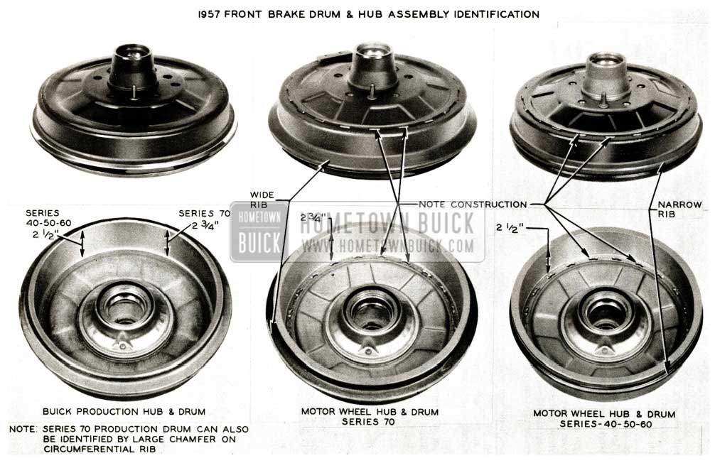
1957 Buick Front Brake Drum Assembly
No change is being made on the rear brake drums; therefore, regular Buick drums will continue to be used at this location on all series.
Replacement parts for service may be ordered as follows:
BUICK DRUMS
Gr. 6.306 Part No. 1174006 Hub and Drum Assy. – Series 40-50-60
Gr. 6.306 Part No. 1174572 Hub and Drum Assy. – Series 70
Gr. 5.809 Part No. 1175682 Drum – Front and Rear Series 40-50-60 & Rear 70
Gr. 6.334 Part No. 1346200 Drum – Front Series 70
MOTOR WHEEL DRUMS
Gr. 6.306 Part No. 1181239 Hub & Drum Assy. Series 40-50-60
Gr. 6.306 Part No. 1181223 Hub & Drum Assy. – Series 70
Gr. 6.334 Part No. 1181271 Drum – Front Series 40-50-60
Gr. 6.334 Part No. 1181272 Drum – Front Series 70
Hub, Gr. 6.307 Part No. 1392735, is the same for all jobs (Motor Wheel and Buick drums). In addition to these changes, both primary and secondary linings at all four (4) wheels will have grooves in them and the same lining will be used on both power and manual brakes.
The primary lining may be identified by a blue daub of paint on lining edge and secondary will have a yellow daub. When submitting product reports on brake complaints, please include the make of drum and color code of linings involved.
The following policy has been established relative to using Motor Wheel drums in service:
- Motor Wheel drums should not be used as replacements for Buick front drums unless both Buick front drums are scored to a point where they will not clean up when rebored to a diameter of 12.083″. Only in those cases where both Buick front drums would have to be rebored to a diameter larger than 12.083″ is it permissible to install two (2) new Motor Wheel drums.
- Motor Wheel drums are not to be used at the rear location as Buick drums have been found to work very satisfactorily at this point.
- If a job equipped with one make drum requires a front drum replacement, another drum of the same make must be used. Under no circumstances should two different makes of front drums be used on one job.
AFA’s which do not comply with the above three conditions will not be accepted, and any drums received in the M.R. Room which should not have been replaced will be returned.
Starting serial numbers by Assembly Plants shown in left column are jobs equipped with Motor Wheel drums:
Flint
Series 40-50-60 – D1059622
Series 70 – D1062085
South Gate
All Series – D2019325
Linden
Series 40 Synch. – D3024057
Series 40-50-60 – D3022514
Series 70 – D3023391
Kansas City
Series 40-50-60 – D4020301
Series 70 – D4020249
Wilmington
Series 40-50-60 – D5019518
Series 70 – D5019960
Atlanta
Series 40-50-60 – D6017703
Series 70 – D6017609
Framingham
Series 40-60 – D7007820
Series 50 – D7007737 to D7007789 and above D7007822
Series 70 – D7007736 to D7007790 and above D7007961
Arlington
Series 40-50-60 – D8014344
Series 70 – D8014578
BRAKE PEDAL HEIGHT SETTING
1957 MODELS
Before adjusting brake pedal height it is most important to make sure the large nut holding the brake cylinder to the cowl is tight, also tighten brake pedal mounting bracket attaching bolts. Lubricate brake pedal mounting spacers, clevis pins and brake pedal return spring with lubriplate at all pivot points. This will help prevent complaints of brake pedal squeak and reduce binding tendencies.
To insure full pedal travel on power and manual brakes and prevent any misunderstanding as to the correct pedal height for 1957 models, we are again reprinting these measurements.
Power and manual brake settings are taken perpendicular from toe-pan or toe-pan mat to top center of pedal pad cover as listed below.
Leave A Comment
You must be logged in to post a comment.