1957 BUICK BODY STYLES
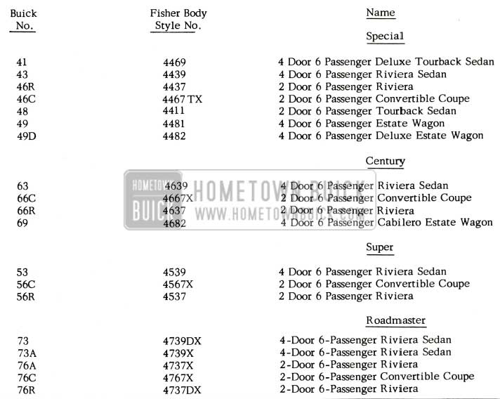
1957 Buick Body Styles
HEADLINER REFINISHING INFO.
1957 Estate Wagon
Requests have been received regarding the proper semi -gloss lacquer colors to use on 1957 Estate Wagon headliners. There are four colors available. The “Duco” mixing machine formula matches for the colors are as follows:
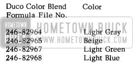
1957 Buick Headliner Colors
All of these colors have a subdued gloss and, therefore, require the addition of “Duco” No. 4528 Flattening Compound to make them correspond in lustre to that of the original Factory finish. The flattening compound must be used in accordance with label instructions.
INSTRUMENT PANEL GLARE
Several requests have been received for information on reducing instrument panel glare, in order to eliminate owner complaints on 1957 models.
In tests conducted at Engineering, it has been found that a non-glare vinyl coating manufactured by Amdt-Palmer Laboratories, Inc., 17730 Dora Street, Melvindale, Michigan, may be applied to the instrument panel safety pad to dull the finish. This material is available from the above source in pints or quarts at approximately $2.50 per quart. The coating is a clear solution suitable for brushing or spraying. Directions for applying this material are as follows:
- Make certain that surface is clean and free of wax.
- Use soft camel hair brush or spray.
- If thinning is necessary, lacquer thinner may be used.
- Stir well before using.
- Allow 20 to 30 minutes drying time between coats.
- Two coats should be sufficient.
- Approximately 1/2 pint will do 4 coats. On cars not equipped with safety pad, the painted panels may be brushed or sprayed with either DuPont Duco #1672 Clear Lacquer (flat) or Ditzler non-glare DCL-451.
The directions for applying the Duco 1672 Clear or Ditzler Non-Glare DCL-451 material are the same as mentioned above for the safety pad.
CAUTION: If applying the material by brush, be sure to keep edges wet and do not brush out. Keep liquid flowing to minimize brush marks. Do not apply in sun or extreme heat.
NOTE: No AFA’s will be accepted to dull finish of panel or pad.
DOOR INNER PANEL WATER DEFLECTOR
All 1957 Models
Whenever service operations are performed on a door assembly where it becomes necessary to disturb the door inner panel water deflector, the deflector must be properly sealed to prevent serious door waterleaks.
For service operations which require access to a particular area of the door inner panel, the water deflector may be cut (DO NOT TEAR) and turned back to provide the necessary access. It is recommended in these instances that the deflector be cut in a straight line and over a portion of the door inner panel with the least depressions. The cut area must be resealed with waterproof body tape.
For service operations necessitating the installation of a replacement water deflector, it is recommended that a sharp scraper be used to break the cement bond which secures the deflector. The replacement water deflector should be trimmed, using the old deflector as a template. Installation of the new deflector should be performed, using a continuous application of approved weatherstrip cement along the edges.
For both complete and partial water deflector removal, the lower edge of the deflector should be checked to make certain it is properly inserted in the slot along the lower portion of the door inner panel. Waterproof body tape should be applied to the water deflector and door inner panel at the ends of the retaining slot to provide a weather seal.
Complete service procedures concerning the door water deflector may be found in past BPS Bulletins.
INSTRUMENT PANEL COVER PAD
The upper instrument panel cover pads used beneath the 1957 upper instrument panel trim, Gr. 14.655, have now been released and are available from the Parts Department. These pads are cut to shape for use in the upper center instrument panel and when the pads are required for the upper side instrument panel, it will be necessary to cut these pads from these center pieces.
Following are the part numbers of these pads: Group 14.655 – Part #4709298 Pad, Instrument Panel Cover Filler (upper center) 1957-40-60
Group 14.655 – Part #4709301 Pad, Instrument Panel Cover Filler (upper center) 1957-50-70
REAR QUARTER PANELS
The rear quarter panels supplied for service on the 1954, 1955 and 1956 Model 49 and 69 Estate Wagons are the same rear quarter panels as used on the Model 41 for these various years.
When installing either the rear quarter outer panel or the rear quarter panel and wheelhouse assembly on an Estate Wagon, it is necessary to rework and reflange these panels to fit the Estate Wagon body. This requires moving the rear compartment lid gutter from the rear section and reflanging of the metal to match the contour of the Estate Wagon upper rear quarter panel.
The upper rear quarter panel and rear quarter window frame are stocked as separate service parts and are shown in the illustration in the Estate Wagon Parts Book.
SEAT CHUCKING
Installation of Anti-Chucking Spring on Power Operated Two-Way Seat Adjuster
1957 Buick
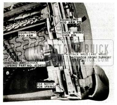
If objectionable fore and aft movement (chucking) of the front seat is encountered on seats equipped with electric horizontal (two-way) seat adjusters, the condition may be corrected by installing antichuck springs and, where necessary, performing reworks as described and illustrated in the following procedure:
- Remove seat side panels. Install an antichuck spring Gr. 11.561 Part #4734125 at both the right and left seat adjuster, as shown in Figure 120.
1957 Buick Seat Assembly
NOTE: File notch for spring in rear leg of adjuster approximately 1/2 inch up from bottom of leg. Lubricate equalizing rod arm pin and slot at both adjusters with Lubriplate.
IF AN OBJECTIONABLE CHUCKING CONDITION STILL EXISTS, PER FORM THE FOLLOWING STEPS:
- Operate seat to a pos1t10n midway between extreme forward and rearward positions.
- Remove seat assembly, including seat adjusters, from body and place upside down on a protected surface. Remove tension spring at right adjuster. Remove anti-chuck spring at both adjusters. Remove left adjuster, including actuator assembly, from seat. Remove equalizing rod from seat.
- Place equalizing rod in vise. Check arm and pin, shown in Figure 120 on both ends of equalizing rod for looseness and, if loose, weld securely.
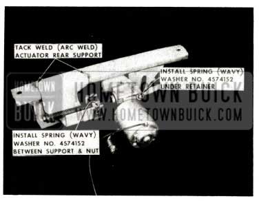
- On the left seat adjuster, tack weld (arc weld) the actuator front and rear supports, as shown in Figures 120 and 121
- Install spring (wavy) washer Gr. 14.155 Part #4574152 between actuator rear support and jack screw nut, as indicated in Figure 121.
1957 Buick Seat Assembly Spring Support
GLOVE COMPARTMENT PACKAGE STOP
All 1957 Models
An Instrument Panel Compartment Box Package Stop Group 10.268 Part #4721191, has been incorporated in production to prevent small items from falling out of the instrument panel compartment when the compartment door is opened. The stop is secured to the instrument panel with the same screws that secure the compartment box, as shown in Figure 122.
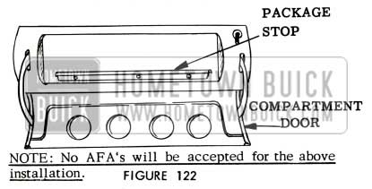
1957 Buick Glove Compartment Package
The stop is available as a service part and can be installed on early production bodies which do not have the package stop.
NOTE: No AFA’s will be accepted for the above installation.
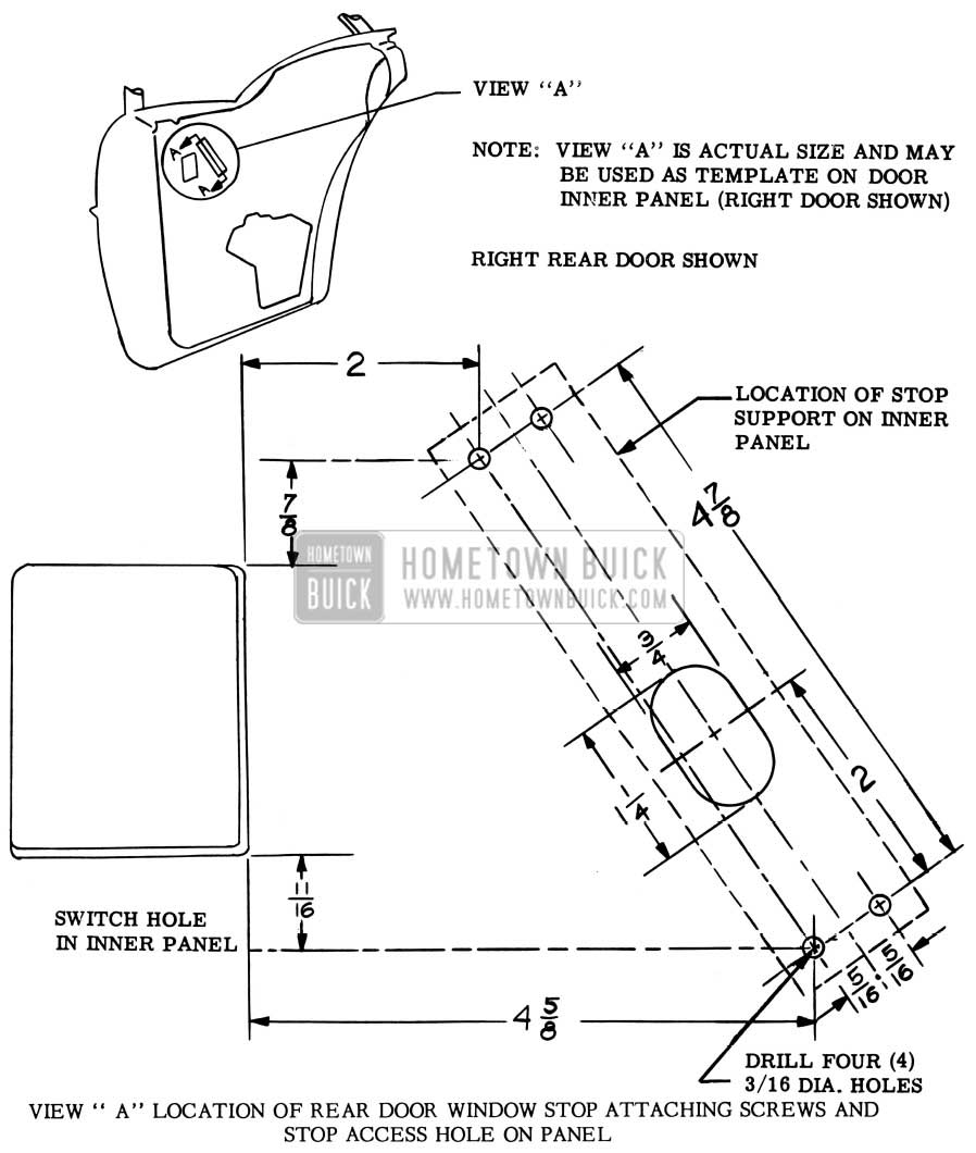
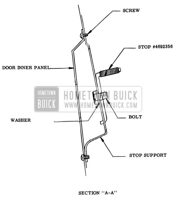
INSTALLATION OF REAR DOOR WINDOW UPPER STOP
To Eliminate Glass Breakage 1957 Buick 41 & 61 Models
If a condition is encountered where the rear door window glass is cracked due to the electric window regulator motor exerting a strain on the door window lower sash channel after the glass has reached the full “up” position, the condition may be corrected by installing a door window stop and support as follows:
The materials required to perform this installation on one (1) door are listed below:
Name and Description – Quantity
.075 Steel Stock 1-1/4 x 6-1/2 – 1
Window Stop Gr.ll.012 Part 4692356 – 1
1/4 I.D. Ext. Tooth Lock Washer – 1
1/4 – 28 x 3/8 Hex Head Bolt – 1
#10 – 24 x 1/2 Pan Head Screw – 4
- Fabricate support for the window stop from .075 steel stock according to the drawing in Figure 123.
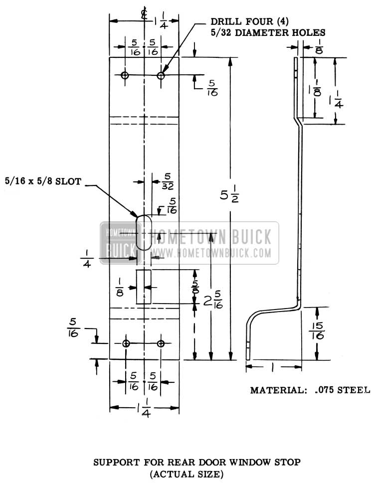
1957 Buick Support for Rear Door Window Upper Stop
1957 Buick Rear Door Window Upper Stop Attaching Screws
1957 Buick Rear Door Window Upper Stop Assembly
1957 Buick Windshield Wiper Arm
SEAT ADJUSTER LOCKING ROD SPRING
1957 Models Equipped With Manually Operated Seat Adjusters
It has been found that in some cases the seat adjuster locking rod center support spring (coil spring) has too much tension which prevents the right seat adjuster from locking properly. If this condition is encountered the spring should be removed and stretched until the tension is reduced sufficiently to allow the right seat adjuster lock to fully engage when the control knob is released.
NOTE: Changes are being made in production to correct this condition.
LOOSE WINDSHIELD WIPER TRANSMISSION ESCUTCHEON
1957 Models
If the windshield wiper transmission escutcheon is loose due to insufficient retention of the windshield wiper transmission spanner nut, the condition may be corrected by installing an additional windshield wiper transmission to escutcheon gasket, Gr. 10.160, Part #4708249.
Assembly plants have been authorized to install the additional gasket as required.
WARRANTY ON PAINT
Following is a new schedule of allowances for Duco used in connection with sheet metal and body refinishing under the warranty. This schedule is based on a new formula which has been revised in line with a Dupont Refinishers Price List No. 31, dated December 31, 1956.
1957 Buick Paint Warranty
So that you will be entirely familiar with the method used in arriving at the average paint cost we are listing the formula used in establishing the average selling price of mixed Duco material. Please note that the average price is for mixed Duco and not for color only.
FORMULA FOR ESTABLISHING AVERAGE SELLING PRICE OF MIXED PAINT MATERIAL
1957 Buick Paint Formula
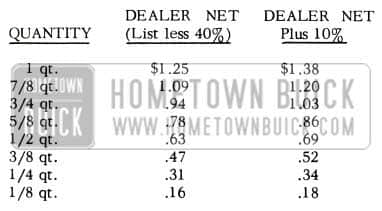
1957 Buick Paint Formula Prices
THINNER
Price in 5 gallon lots. The thinner usually purchased by dealers and recommended by paint manufacturers for general purpose work is $1.70 and thinner used for reduction of color coats is $2.10 per gallon. The latter is used in arriving at the above cost.
The mixed cost was determined by adding the percentage of color and thinner to obtain the cost of a mixed gallon of material. The cost of a mixed gallon was then marked up to give a list price which would allow a 40% discount to dealers.
The average price is determined by taking into consideration the percentages of colors used in production, the ratio of primer-surfacer to color and the above list prices.
1957 Buick Color Formula
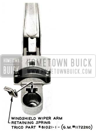
WIPER ARM RETAINING SPRING
1957 CAM-O-MATIC
We have been advised that the windshield wiper arm retaining spring was omitted in the manufacturing of approximately one-week supply of wiper arms.
Omitting of the retaining spring may allow the wiper arm to work out from a fully seated position on the wiper transmission shaft. If the splines on the end of the shaft are visible underneath wiper arm, the wiper arm should be removed for inspection. In case the spring is missing, install retaining spring Trico No. 81021-1, or Gr. 0.147 Part 1172260. See Figure 126.
NOISES IN BODY
1957
Several Dealer Product Service Reports have been received stating that there is an excessive amount of exhaust and road noise leakage into the body compartment. Almost all these reports can be traced to leakage into the body occasionally combined with an excessive exhaust noise which aggravates the condition. This noise generally falls into three distinct classifications:
- Noise Leakage Into Body
ln most instances this difficulty will exist on Estate Wagons and Model 73, and may be corrected by sealing off body noise leakage paths and packing insulation into the cavity above the rear wheel, as described below in Parts I and II. - ”Putt Putt”
This is often described as “V-8” throb or as a sound similar to a motor boat; and if present, is most common on dual exhaust equipped cars. This sound may be greatly reduced by installing and properly locating 1-3/4 inch O.D. resonator outlets as described in Part III. - ”Off Idle Boom”
This disturbance has a very low pitched overtone which is present at engine speeds just above idle. (600 – 900 r.p.m.) This sound, if present may also be reduced by installing properly located 1-3/4 inch O.D. resonators.
The procedures used for correcting the three conditions named above are:- Sealing of all body noise leakage paths.
- II. Install insulation in body cavity in wheelhouse area.
Resonator outlet change.
Each of the three methods for correcting this noise may be used individually, or if necessary, collectively. Most of the excessive noise attributed to the exhaust system can be corrected as described by Methods I and II below. However, none of the following work should be done until all interferences are removed throughout the exhaust system. Also any build up of undercoating material which bridges the space between frame and body must be removed.
- Sealing Of All Body Noise Leakage Paths
All grommets must be installed properly. Cases have been reported where the license plate wire grommets through the inner and outer rear body panels and the grommets above the gasoline tank gauge unit were either missing or improperly installed. Holes have been found between the underbody and wheelhouse, on Estate Wagons, where improper welding and sealing present a bad leakage path. These holes, and all other welded joints must be sealed with Permagum or Auto-Body Sealer. The outer wheelhouse upper panel, directly over the rear wheel, has been found to be out of place leaving openings into the cavity above. This unit should be pushed back into place and properly sealed. The tail gate and lift gate should be checked for proper seal to body, particularly the tail gate lower horizontal seal. - Install Insulation In Body Cavity In Wheelhouse Area.
The second correction reduces road and exhaust noise leakage into the body on all Estate Wagons and four-door hardtop models and consists of packing insulation into the body cavity just above the wheelhouse. This may be done by cutting a piece of bulk hood insulation material Gr. 8.021 Part #1165722, 56 inches long and 12 inches wide. The insulation must be rolled into a roll 12 inches long and approximately 7 inches in diameter with the last complete roll covered with waterproof plastic by wrapping approximately 24 inches of the outer end of this insulation with thin plastic, such as poly-ethylene film (material used to cover front seat of cars when shipped from factory) which can be purchased at most hardware stores. See Fig. 127.
1957 Buick Body Cavity Wheelhouse Area
It is important that this be done so the insulation will not hold moisture against a metal surface causing a rusting condition. Then install the roll into the cavity above the wheelhouse as shown. Access to this area is gained through the opening just above the resonators and to the rear of both rear wheels. On Estate Wagons, an extra piece must also be cemented to both vertical inner quarter panels covering all of the flat area behind the rear wheels. This should be cemented in place using weatherstrip cement on the outer side of this panel. This pad is used on after jobs in production. Rear quarter extensions should be removed for this operation. See Figure 128.
1957 Buick Wheelhouse Insulation
Installation of a trunk floor mat will also be of material help on wagons when fitted into the spare wheel compartment and cemented in place.
On all Model 73 bodies, the body cavity, in back of the outer ends of the rear window garnish molding should be stopped tight with fiber glass insulation. It is particularly important that this be accomplished. There is an opening in the body inner structure at this location through which this packing can be inserted. See Figure 129.
1957 Buick Wheelhouse Insulation Assembly
Resonator Outlet Change
The resonator change is in the outlet pipe and consists of reducing the diameter of the O.D. of the two (2) inch outlet to 1 3/4″ for a section approximately two (2) inches in length. See Figure 130.
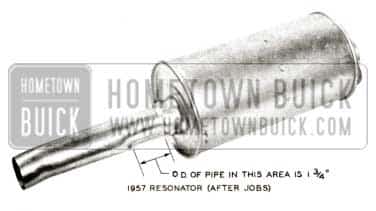
1957 Buick Resonator Outlet
The 1 3/4″ restriction will make there sonators operate more effectively, thereby reducing noises “A” and “B” mentioned above. Resonators having the 1 3/4″ restriction in the outlet pipe are available through the Parts Department under Gr. 3.702; left resonator Part No. is 1175285 and the right is 1175284. It is important when installing the resonator to position the outlet so that it is centered in the tail pipe extension and that the rear bumper is not grounded on the body or tail pipe.
REAR COMPARTMENT LID BUMPERS
1957 Model 56C and 76C
If a condition is encountered where the front outer corners of the rear compartment lid contact and chip the paint at the front edge of the compartment opening when the lid is lowered or raised, it may be corrected by installing a bumper as outlined in Figure 131.
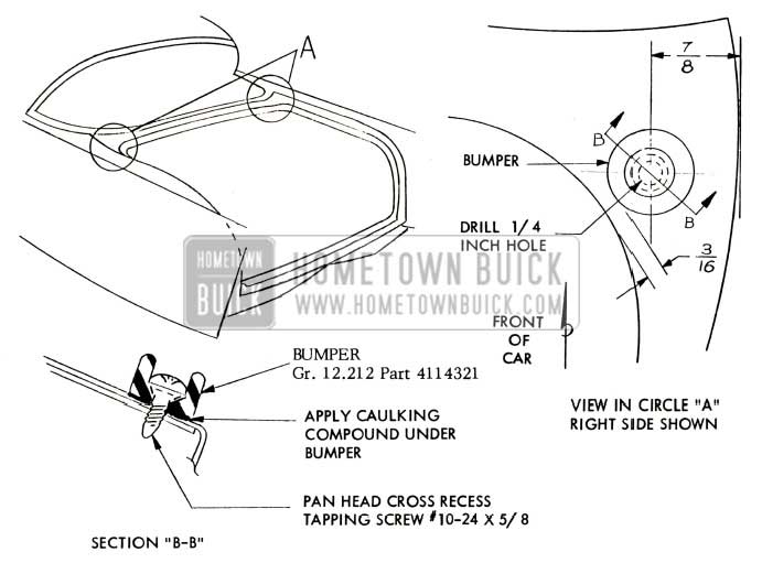
1957 Buick Rear Compartment Lid Bumpers
- Open lid and drill 1/4 inch diameter hole at location indicated in View “A”, at the right and left side of the compartment opening.
- Apply sufficient amount of body caulking compound at bottom surface of each bumper to effect a seal.
- Install each bumper and secure with attaching screw as shown in Section “B-B” Fig.131. NOTE: In some cases it may be necessary to install a rubber washer (spacer) between the bumper and body metal, to obtain required contact of bumper to compartment lid.
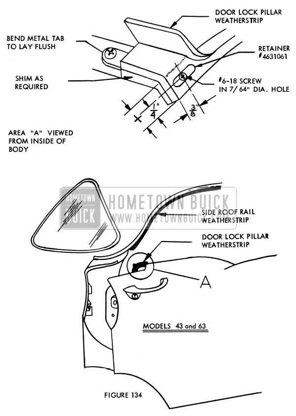
WATER LEAKS AT REAR DOOR LOCK PILLAR
1957 Buick Models 41-43-61-63
If a waterleak is encountered on early production bodies between the top of the rear door lock pillar weatherstrip and the bottom of the horizontal surface (cove section) of the rear body lock pillar on Models 43 and 63 between lower rear end of the side roof rail weatherstrip and/or the upper forward end of the rear door lock pillar weatherstrip, the condition may be corrected using the following procedure:
- Check door alignment and correct if necessary.
- Remove forward screw from side roof rail filler, countersink hole, apply medium -bodied sealer and install a flat-headed countersunk self-tapping screw (non-corroding type).
- Remove rear door garnish molding and, on Model 43 and 63 the screw used to retain forward end of door weatherstrip.
- Drill a 1/4″ diameter drain hole as indicated in Figure 132 and 133.
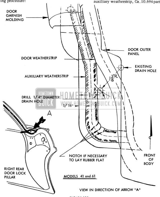
1957 Buick Rear Door Lock Pillar
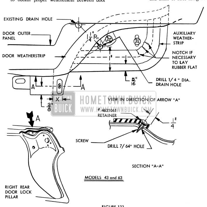
1957 Buick Rear Door Lock Pillar Repair
NOTE: If additional retention is desired at this point, drill a 7/64″ diameter hole through door weatherstrip, shim and door inner panel at location indicated in the sketches, Figures 133 & 134. Secure door weatherstrip and shim to door using weatherstrip retainer, Gr. 10.695 part number 4631061, and a #6-18 oval or flatheaded countersunk self-tapping screw.
1957 Buick Rear Door Lock Weatherstrip
- On Models 43 and 63 bend tab at forward end of door lock pillar weatherstrip to follow contour of shim and door metal. Reinstall original retaining screw.
- Reinstall rear door garnish molding.
- Lubricate door weatherstrips with a silicone rubber lubricant.
- Check door alignment and weatherstrip contact to insure proper weatherseal.
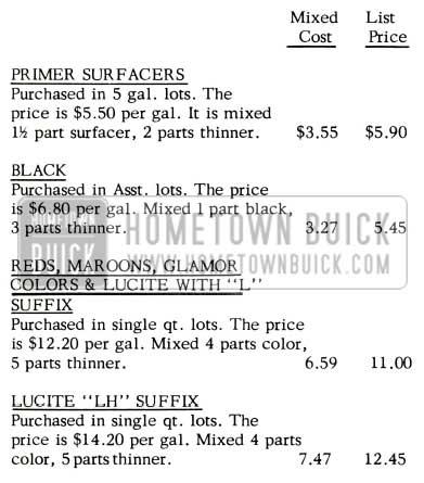
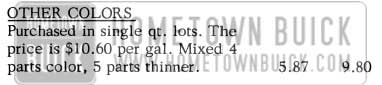
CHANGE IN DUCO PRICES
The following is a new schedule of allowances for Duco used in connection with sheet metal and body refinishing under the warranty. It will be noted that there is an overall increase in the cost of material and a more liberal method of determining the cost of lacquer by using prices listed for purchases in smaller quantities. The new rates will apply to any warranty refinishing done after August 1.
1957 Buick Duco Prices Change Normal Colors
1957 Buick Duco Prices Change Special Colors
So that you will be entirely familiar with the method used in arriving at the average paint costs, we are listing below the formula used in establishing the average selling price of mixed Duco material. Please note that the average price is for mixed Duco and not color only.
Formula For Establishing Average Selling Price Of Mixed Paint Material Thinner
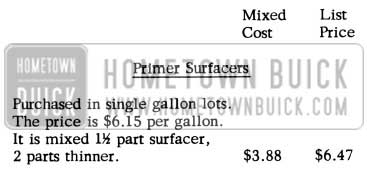
1957 Buick Duco Prices Change Primer
1957 Buick Duco Prices Change Primer Surfacers
Price in 5 gallon lots. The thinner usually purchased by dealers and recommended by paint manufacturers for general purpose work is $1.70 and thinner used for reduction of color coats is $2.15 per gallon. The latter is used in arriving at the above cost.
The mixed cost was determined by adding the percentage of color and thinner to obtain the cost of a mixed gallon of material. The cost of a mixed gallon was then marked up to give a list price which would allow a 40% discount to dealers.
The average price is determined by taking into consideration the percentages of colors used in production, the ratio of primer-surfacer to color and the above list prices.
1957 Buick Duco Average Prices Change
CRACK FRONT DOOR OUTER PANEL
1957 – 40 & 60 Series
If cracks or tears are encountered in the front door outer panel in the ventilator area, as indicated in Fig.135, the ventilator assembly should be removed and the cracks or tears should be welded to the edge of the door outer panel return flange.
1957 Buick Front Door Outer Panel
NOTE: Prepare asbestos paste and place around area to be welded to keep metal distortion and paint damage to a minimum. Metal finish and spot finish welded areas.
SEAT ADJUSTER SWITCH CHANGE
1957 Electric Front Seat
The switch used on the 1957 Electric Front Seat Adjusters (6-way seats) has been changed by revising the switch case to accommodate a new Electric Front Seat Adjuster Switch to Escutcheon Clip. This new Clip provides improved retention of the switch to the escutcheon. In order to include this improved type of switch to escutcheon clip in cars when a replacement switch is installed, the new revised switch will be supplied for all service replacements of the original switch when stock on hand is exhausted. When installing the new switch in place of the original switch, it will be necessary to order and install four of the new clips which are used with this switch. Following are the part numbers involved:
Group 11.558 – 4683843 Switch-Electric Front Seat Adjuster 1957 (Except 48) For use on Tilt Type 6-Way Seat Adjusters
To be replaced by:
Group 11.558 – 4717647 Switch-Electric Front Seat Adjuster 1957 (Except 48) For use on Tilt Type 6-Way Seat Adjusters
NOTE: When installing Switch 4717647 on 1957 cars which used Switch 4683843, it will be necessary to order and install 4-Group 11.558 – 4717648 Clip-Front Seat Adjuster Switch.
DOOR LOCK CONTROL ROD RATTLE
1957 Buick Models 41-61
If an objectionable rattle is encountered in the front doors of the above style bodies caused by vibration of the door lock remote control connecting rod, the condition may be corrected by cementing a piece of sponge rubber or weatherstrip to the ventilator division channel.
- Remove door belt finishing molding and door trim assembly. Detach inner panel water deflector sufficiently to gain access to front access hole.
- Cement a piece of sponge rubber (approximately 2-1/2″ long x 5/8″ wide x 5/8″ thick) or a piece of cement on type weatherstrip (approximately 2-1/2″ long) to outer side of ventilator division channel’ in area of connecting rod, as shown in Figure 136. Apply weatherstrip cement to contacting surface of both parts.
1957 Buick Door Lock Control Rod
Reseal inner panel water deflector, then install door trim assembly and door inside hardware.
BOLTS MISSING
FROM INSTRUMENT PANEL
We have received several dealer product reports which state that some screws in the center section of the padded upper half of the instrument panel are missing. We have been advised by Engineering that this panel is designed, for appearance reasons, to use only two (2) screws on the underside of this pane l, one at each corner. However, the painted panel is designed to use six (6) therefore, it will not be necessary to install four more screws when a padded pane I is used.
REAR COMPARTMENT LEAKS
All 1957 Buicks
On some early production bodies, rear compartment waterleaks have been caused by unsealed production drain holes in the rear compartment lid inner panel.
All drain holes contacted by the rear compartment weatherstrip and all drain holes outboard of the weatherstrip contact area on forward edge of lid should be sealed with body caulking compound. Application of caulking compound should be restricted to the amount required for sealing the hole and should be flush with metal surfaces.
REAR COMPARTMENT HINGE REPAIR
1957 Buick 56C and 76C
On some early production convertible bodies, the rear compartment lid hinge strap may be fractured at the hinge pin location, shown in View “A”, Figure 137.
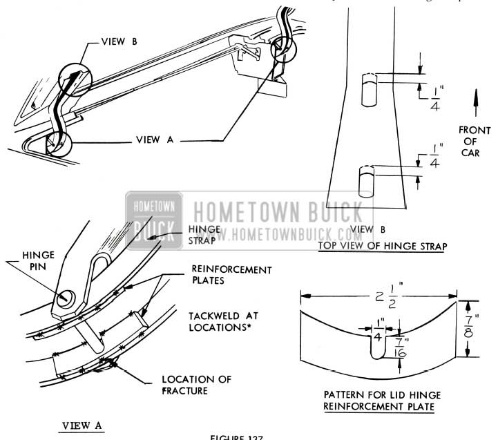
1957 Buick Rear Compartment Hinge
If this condition is encountered in the field, the hinge may be repaired by installing reinforcement plates as outlined in the procedure.
lf an excessive gap (larger than 1/8″) is present between the forward edge of the rear compartment lid and rear compartment front panel after the lid has been adjusted as far forward as possible, the hinge strap attaching holes may be lengthened an additional 1/4” forward as indicated in View ”8”.
Installation of Hinge Strap Reinforcement
- Remove affected hinge (s) from hinge box.
- Using reinforcement plate pattern, cut plate from 1/8″ thick cold rolled steel stock. Two plate required for each hinge.
- Weld reinforcement plates to hinge straps at locations indicated in View ”A”.
- Install hinge in hinge box.
Providing Additional Forward Adjustment of Rear Compartment Lid
- Remove rear compartment lid from hinge straps.
- File forward edge of lid hinge strap attaching holes as shown in View “B”.
- Install compartment lid to hinge straps.
WATERLEAKS AT SIDE ROOF RAIL WEATHERSTRIP
1957 Buick – 43-63 Models
If a condition is encountered where “waterleaks” between the front and/or rear door window frame and the side roof rail weatherstrip, cannot be eliminated by adjusting the door and/or door window assembly, the condition may be corrected by installing a waterproof shim between the side roof rail and the side roof rail weatherstrip retainer as indicated in Section “A-A”, Fig. 138.
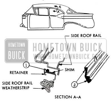
1957 Buick Side Roof Rail Weatherstrip
- Mark length of weatherstrip and retainer to be shimmed.
- Remove weatherstrip and retainer from body.
- Cement a waterproof shim to the area of the retainer which requires shimming.
NOTE: The size of the shim will vary with the conditions encountered. Be sure to taper ends of shim to insure proper fit of retainer to side roof rail.
- Apply a bead of medium -bodied sealer along length of weatherstrip retainer as indicated at “1” in Section “A-A”, Fig.138, and install retainer to side roof rail.
- Apply weatherstrip cement to front end of side roof rail weatherstrip as indicated at “2” in Section “A-A”, 138; then install weatherstrip to retainer.
REAR DOOR CENTER GUIDE CHANGE
1956 MODELS 53-73
In order to eliminate the possibility of the parts binding at the attachment of the Rear Door Window Center Guide to the Rear Door Window Lower Sash Channel, with resultant loosening of the attaching shoulder bolt during operation of the window, the method of attachment was changed during 1956 production. The center guide attaching bolt was revised to change the center guide attaching hole from a round to a square hole and the weld nut was removed from the center guide. Since these parts are not interchangeable as separate parts, first and second type parts are released. However, when present stock of the lower sash channel is exhausted, only the second type channel will be available. This will require the installation of a second type guide and bolt when installing the second type sash channel in a car with first type parts. Both the first and second type guide and bolt will be stocked as service parts.
Following are the parts involved:
Gr. 10.747 – 4159634 Channel-Rear Door Window Sash – Lower – Right
Gr. 10.747 – 4159635 Channel-Rear Door Window Sash – Lower – Left 1956-53-73 Up to Body
To be replaced by:
Gr. 10.747 – 4232546 Channel-Rear Door Window Sash – Lower – Right
Gr. 10.747 – 4232547 Channel-Rear Door Window Sash – Lower – Left 1956-53-73 After Body
Note: When using Parts 4232546 and 423254 7 as replacements of 4159634 and 4159635, it will be necessary to install 1 – Gr. 10.765 – 4690320 Guide and 1 – Gr. 10.765 – 4689522 Bolt.
Gr. 10.765 – 4670266 Guide-Rear Door Window Center 1956-53-73 Up to Body
Gr. 10.765 – 4690320 Guide-Rear Door Window Center 1956-53-73 After Body
Gr. 10.765 – 4671385 Bolt-Rear Door Window Center Guide 1956-53-73 Up to Body
Gr. 10.765 – 4671386 Bolt-Rear Door Window Center Guide 1956-53-73 After Body
Change Points will be furnished in the Parts Book.
WATERLEAKS AT VENTILATOR WEATHERSTRIP
All 1957 40 and 60 Series
If a waterleak is encountered between the top of the ventilator glass channel assembly and the ventilator weatherstrip, the condition may be caused by improper assembly of the ventilator tee shaft to the ventilator regulator shaft. This condition may be corrected as follows:
- Remove door belt finishing molding and door inside handles.
- Detach door trim assembly and door inner panel water deflector sufficiently to gain access to the ventilator tee shaft attaching screw.
- Loosen ventilator tee shaft attaching screw shown in Fig. 139.
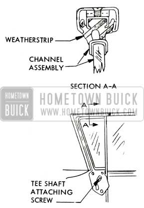
1957 Buick Weatherstrip
Raisechannelassemblysufficiently to make proper contact with weatherstrip, then tighten tee-shaft attaching screw.
ROUGH EDGES ON GLOVE BOX
1957 Buick – All Models
If the appearance of the front of the instrument panel compartment box is objectionable due to the rough edges, which are exposed when the compartment door is opened, the condition may be corrected by sanding the affected edges.
After the sanding operation, the reworked edges should be wiped with a damp oily cloth to darken the off color edges.
INOPERATIVE REAR COMPARTMENT LOCK
1957 Buick – All Models
If a condition is encountered on early-production units where the rear compartment lid will not unlock by turning the key, the condition may be corrected by using the following procedure:
- Check the alignment of the rear compartment lid to the rear compartment opening and the alignment of the rear compartment lid guide to the guide bracket on the rear end panel.
- Apply silicone rubber lubricant to the rear compartment gutter weatherstrip, lower section.
- Adjust rear compartment lid lock striker as far rearward as possible. (Remove emergency striker spacer if present).
- Apply stick -type lubricant to lock assembly as indicated in Figure 140 and to mating surface of striker.
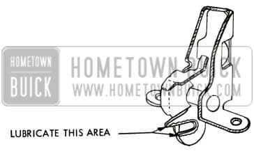
1957 Buick Rear Compartment Lock Repair
GLOVE BOX DOOR STOP DISENGAGING
1957 Buick – All Models
To prevent the instrument panel compartment door stop from disengaging from the instrument panel when the door is opened, each door stop retaining leg may be lengthened by welding a 1 ” long and 1/16” thick piece of steel to the stop as indicated in Figure 141.
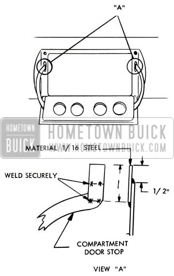
1957 Buick Glove Box Door Stop
A production change has been incorporated to lengthen the stop retaining leg, thereby correcting this condition on later production bodies.
GLOVE BOX DOOR LIGHT SWITCH NOT ACTUATING LIGHT
1957 Buick – All Styles
If the instrument panel compartment door does not actuate the light switch plunger sufficiently to shut off the compartment box light when the door is closed, the condition may be corrected by installing a screw and washer to the door inner panel as shown in View “A”, Figure 142.
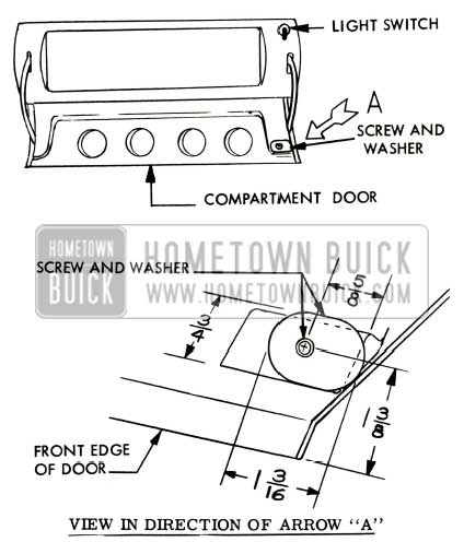
1957 Buick Glove Box Light Switch
- Drill a 1/8″ diameter hole in instrument panel compartment door inner panel at location indicated in View “A”, Figure 142.
- Secure washer Gr. 10.703 Part #4665932 with a #8 – 15 x 3/8, washer-faced, self-tapping screw.
NOTE: If specified washer is not available, it may be cut using the dimensions shown in Figure 142 from .035 controlled steel stock. Be sure to fil e all edges smooth.
- Close door and check operation of switch.
RAISING OR LOWERING CONVERTABLE TOP
1957 Buick – Models 46C & 66C
To eliminate interference which may cause damage to the folding top and/or the top side roof rail pads when the top is being stacked or while top is in a stacked position, the following items should be carefully checked.
- The distance from the top rear corner edge of the sea t back to the forward surface of the pinchweld finishing molding should be 12″ as shown in Figure 143. The vertical distance from a line extended directly outboard from the top outer corner of the seat back to the top surface of the pinchweld molding should be 3/4″ as shown in Figure 143.If necessary, adjust the rear seat back as required.
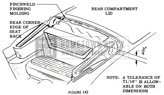
1957 Buick Convertible Top Operation
NOTE: It is important that the rear seat back be properly seated on the rear seat back hangers. Two (2) cardboard tabs at the back of the rear seat back may extend downward directly over the left and right rear seat back hangers, thus preventing proper seating of the back assembly and raising the vertical distance of the rear seat back as much as one (1) inch. If this condition is encountered, bend the cardboard tabs inward sufficiently to allow proper seating of the back assembly.
- The rear seat back top boot retainer should be centered in relation to the rear seat back assembly. This will locate the ends of the top boot retainer approximately two (2) inches inboard from the left and right side edge of the rear seat back assembly as shown in Figure 144.
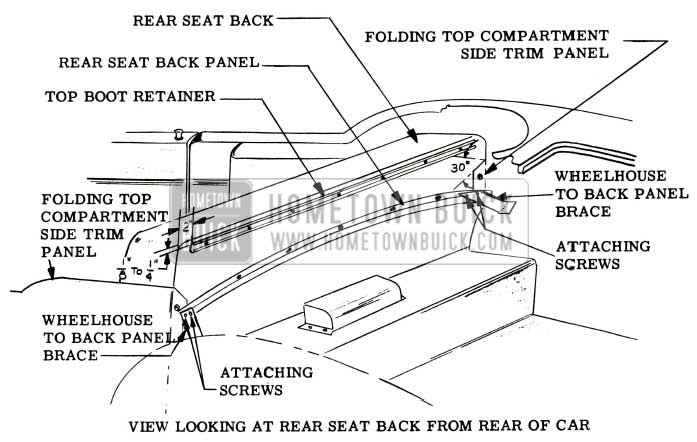
1957 Buick Convertible Top Raising or Lowering
The top boot retainer should be located 1/8” to 1/4” below the top edge of the rear seat back assembly as shown in Figure 144. Elongated holes have been provided in the retainer to obtain this adjustment. If sharp corners are encountered on the top boot retainer, they should be eliminated, as they may snag the folding top and/or the top side stay pads when top is being raised or lowered. Adjust top boot retainer and remove all burrs as required.
NOTE: Present production is trimming the upper rear inboard corner of the folding top compartment side trim panel at a 30° angle. If early production side trim panel upper rear inboard corners interfere with the raising or lowering of the folding top assembly after properly being attached to the rear seat back, then the upper rear inboard corner can be trimmed as follows:
- Remove trim material sufficiently to gain access to rear inboard upper metal panel.
- Trim metal panel at approximately 30° angle and remove all burrs from panel.
- Retrim and recement material as required to give panel a finished appearance.
- The wheelhouse to rear seat back panel brace is spotwelded to the wheelhouse panel and attached to the rear seat back panel by two (2) screws as shown in Figure 144.
NOTE: The inboard attaching screw not only secures the wheelhouse brace but also the folding top compartment bag material to the rear seat back panel assembly. All sharp edges should be re moved from the brace as damage could occur to the folding top material while top is in a stacked position. If attaching screws are broken or missing or broken spotwelds are encountered, repair wheelhouse to back panel brace as required.
- The folding top compartment bag material should be fastened to the rear seat back panel by seven (7) stud fasteners and a screw at each corner. The inboard attaching screws, as mentioned above, also retain the wheelhouse to back panel brace. It is important that the bag material is securely fastened by a screw at each end because the bag material has a tendency to pull rearward when the folding top is being stacked. This could expose the wheelhouse to back panel brace and exposed edges on the brace could damage the folding top material when top is in a stacked position. If screws or stud fasteners are broken or missing, replace as required.
BUICK PAINT COLORS
1957 Models
ln order to combine and furnish you with complete refinishing information for the 1957 models, we are again listing the DuPont “Duco” Lacquer Stock Number for both exterior and interior colors.
Some of this information has previously been published in various BPS Bulletins and includes the new Spring Colors; this together with the1957 Buick Color Chart Bulletin No. 28, will provide you with complete paint information.
EXTERIOR COLORS
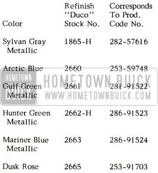
1957 Buick Exterior Paint Colors
INTERIOR COLORS
1957 Buick Interior Colors
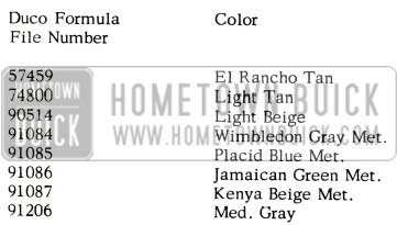
NOTE: Duco mixing machine formulas only are available for the following 1957 Buick interior colors:
Dulux Formula File Number – Color
57459 El Rancho Tan
74800 Light Tan
90514 Light Beige
91084 Wimbledon Gray Met.
91085 Placid Blue Met.
91086 Jamaican Green Met.
91087 Kenya Beige Met.
91206 Med. Gray
NOTE: Dulux mixing machine formulas only are available for the following 1957 Buicks molding accent colors:
Dulux Formula File Number – Color
56505 Tangerine
56515 Green
56516 Blue
INSTALLATION OF SOLENOID COVER
On 1957 Power Operated Six-Way Seat
We have received several field reports concerning loose solenoid covers on early production bodies equipped with power operated six-way seat assemblies. This condition can be corrected by first disconnecting the solenoid to spinning nut ground wire, straightening the solenoid cover attaching tabs; then wrapping three (3) or four ( 4) layers of 1/4″ wide tape around the front and rear edge of the solenoid cover as shown in Figure 145.
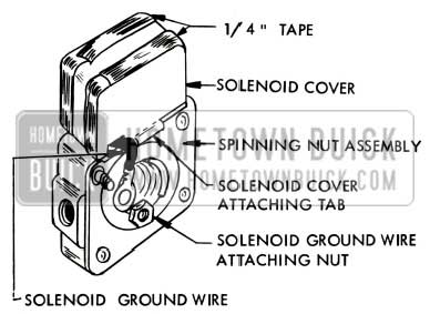
1957 Buick Selenoid Cover
When the cover has been securely taped, carefully crimp the solenoid cover attaching tabs tight over the tape and secure ground wire with attaching nut.
Changes have been made to correct this condition in production by using a specially designed clip to retain the solenoid cover.
SOLENOID WIRING INTERFERENCE
1957 POWER OPERATED SIX-WAY SEATS (All Series)
If solenoid wiring interference is encountered on the power operated six-way seats or when service operations are performed where the seat adjuster solenoid wires are disturbed, the wiring installation should be corrected as follows:
- Operate seat adjusters to a full “up” position. Remove front seat side panels.
- Detach seat adjuster wiring harness and front solenoid wire connector from clips on seat bottom frame. On seats equipped with front seat back lighter, disconnect lighter harness from feed wire and from clip on floor pan.
- Remove seat adjuster to seat frame attaching bolts; then remove front seat assembly (less seat adjuster assembly) from seat adjusters.
CHECKING AND INSTALLING WIRING
- Check to see that the rear solenoid wire connector is installed under snap-on clip, as shown in Figures I46 and 147.
- Where present, remove snap-on clip securing center solenoid wire to adjuster linkage. Tape center solenoid wire and lead wire to the center torque tube, as shown in Fig. 146 & 147.
- On Series 40 and 60, install seat assembly to seat adjusters. Install seat adjuster wire harness and, where present, seat back lighter harness to clips on seat bottom frame and connect harness to lead wires. Install front solenoid wire connector and snap-on clip to inner flange of seat bottom frame, as shown in Fig. 146.
- On Series 50 and 70, check location of wire harness clips on floor pan. If clips are present at locations “X” and shown in Fig. 147, eliminate clip at location “X” and move cup at location “Y” to new location, shown in Figure 147. This new location should place the clip away from the front of the actuator motor and keep it in the area between the front and rear floor carpets.
- For a length of five (5) inches remove tape securing the front and the rear solenoid lead wires together. See Figure 147.
- Install seat adjuster wire harness under newly located clip “Y” on floor pan, as shown in Figure 147.
- Temporarily connect seat adjuster control switch to junction block on wire harness. Operate seat adjusters to limits of horizontal and vertical positions to determine that there is no wiring interference with adjusters.
- Install seat assembly to seat adjusters. Install seat adjuster wire harness and, where present, seat back lighter harness to clips on seat bottom frame. Connect harness with lead wires. Install front solenoid wire connector and snap-on clip to inner flange of seat bottom frame, as shown in Figure 147.
- Operate seat assembly to the full “forward” and “up” position. Position wire harnesses under newly located clip “Y” on floor pan, so that slack in wire harness between seat and clip on floor pan is taken up, as shown in Figure 147.
- Check operation of seat to extreme limits of horizontal and vertical positions.
GAPS BETWEEN FOLDING TOP & QUARTER MOLDING
1957 Buick 50-70 Convertible Bodies
If a gap between the folding top material and the rear quarter pinchweld finishing molding, at the radius area, presents an objectionable appearance and/or allows an excessive amount of water to be directed into the folding top compartment drain gutter, the condition may be corrected as follows:
- Detach the folding top compartment bag from the rear seat back panel and check the outer ends of the rear trim stick assembly for rubber fillers between the trim stick and inner panel. See Figure 148. If the fillers are present, remove the trim stick outer attaching screws and remove the fillers.
NOTE: On early production bodies with eleven (11) trim stick attaching screws and fillers, remove the two (2) outer fillers from each end of the trim stick.
On later production bodies with thirteen (13) trim stick attaching screws and fillers, remove the three (3) outer fillers from each end of the trim stick.
ESTATE WAGON WATER AND DUST LEAK CORRECTION
Following is a reprint of Special Service Letter – Dealer No. 216 dated June 19, 1957, covering A. Estate Wagon Water Leaks and B. Estate Wagon Dust Leaks:
- Estate Wagon Water Leaks – We have received several reports of water leaks in the rear compartment of the 1957 Buick Estate Wagons. After an investigation of these reports we have traced most of the leaks to the following:
- Improperly aligned tail gates – In many cases in order to correct a water leak all that need be done is to correct the alignment of the tail and lift gate. This can be done by loosening the hinge attaching bolts and shifting the lift and tail gate as required to obtain proper alignment.
On most early production Estate Wagons, difficulty was experienced in maintaining the correct adjustment at the lift gate hinge. This condition existed because of two smooth steel surfaces mating together. (The lift gate hinge and the body). The lack of friction at this point allowed the hinge to slip out of adjustment in time, no matter how tight the holding screws were torqued. This condition was eliminated later in production by using two (2) antiskid gaskets, Gr. 12 .184 Part #1183054, between the body and each upper lift gate hinge. See Fig.155. It is recommended that anti -skid gaskets be used (four (4) per car) whenever it is necessary to align the lift gate on jobs not so equipped. - Improperly installed weatherstrip – On some of the first jobs it was found that the porous surface of the weatherstrip which is cemented to the body opening does not give sufficient adhesion to withstand the scrubbing action of the lift gate when it is closed. A new type of weatherstrip with a “full skin”, Gr. 15.269 Part #1177383, is now being used at this location to correct water leaks. See Fig. 155. When a new weatherstrip is used, the following procedure must be observed:
- Improperly aligned tail gates – In many cases in order to correct a water leak all that need be done is to correct the alignment of the tail and lift gate. This can be done by loosening the hinge attaching bolts and shifting the lift and tail gate as required to obtain proper alignment.
- Remove all traces of the old weatherstrip and cement. The surface to which the weatherstrip is to be cemented must be clean.
- Apply a thin coat of 3M Super Weatherstrip Adhesive to body opening and the weatherstrip on the side which makes contact with the body.
- Allow cement to dry completely.
- Apply second coat of adhesive to weatherstrip and install immediately.
- Allow approximately 30 minutes before closing tail or lift gate.
- Make certain retainer clips, Gr. 12 .269 Part #11 77976, are installed. See Fig. 155.
- Improperly assembled gates – We have been informed that on some early jobs the tail gate was not properly sealed at the access hole cover and the handle and plate assembly. Water would enter the tail gate by coming through around the push button lock assembly. The water then falls off the lock assembly onto the inner panel and trickles under the access hole cover and beneath the linoleum cover and onto the floor. This accompanies another problem, and that is that on some of the early cars there was no drain hole provided in the bottom of the tail gate; therefore, water could not drain out and would accumulate between the inner and outer panels.
The access cover and the push button lock assembly may be sealed by using Auto Body Sealer; however, it will be necessary to remove the linoleum covering. In most cases, the linoleum is damaged during removal and must be replaced.
If water is trapped between the inner and outer panels, it is recommended that a drain be provided at the bottom of the inner panel. This may be done by drilling two (2) 3/16″ holes 1/2″ apart and removing metal between these holes. Then, install the dust sealing strip, Gr. 12.269 Part #4688521. The sealing strip is held in place with two (2) retainers, Gr. 10.694 Part #4685752. These retainers are pressed into the two outer 1 /8” diameter holes. See Figure 155.
- Improperly assembled gates – We have been informed that on some early jobs the tail gate was not properly sealed at the access hole cover and the handle and plate assembly. Water would enter the tail gate by coming through around the push button lock assembly. The water then falls off the lock assembly onto the inner panel and trickles under the access hole cover and beneath the linoleum cover and onto the floor. This accompanies another problem, and that is that on some of the early cars there was no drain hole provided in the bottom of the tail gate; therefore, water could not drain out and would accumulate between the inner and outer panels.
1957 Buick Estate Wagon Rear Opening
In a few cases, it has been reported that the seam between the inner and outer pane l across the top of both the tail gate and lift gate was not properly sealed. This will allow the water to get between the inner and outer panel, causing a leak at any location where the inner panel screw holes or joints are not sealed.
Some leaks have been experienced on 69 models at the roof panel moulding. These leaks are quickly identified because of their location. The water will be noticed on the headlining. If this type of leak is encountered, it will be necessary to install a new nut and washer, Gr. 12.812 Part #1177404.
- First, and probably one of the most important items to check, is the contact of body opening weatherstrip. Weatherstrip contact must be 100% all the way around the lift and tail gates. It is particularly important to check lower corners of the tail gate, as a few jobs have been found where the weatherstrip across the bottom of the tail gate has been too short, leaving an opening of 1/4″ in one of these corners. If this weatherstrip is too short, it will have to be replaced with a new weatherstrip Gr. 12.269, Part #1177353, making sure that this new weatherstrip makes the desired contact with the corners of the body opening weatherstrip, Gr. 12.269 Part #1177383.
- On some jobs, dust appears to come up from under the floor. These leaks may be traced to one of the following areas:
Some of the first jobs that were built did not have the grommets Gr. 9.775, Part #1165193, for the license plate lamp wires, allowing dust to enter that area. Naturally, if this condition is found, the grommets must be installed. See Figure 156.
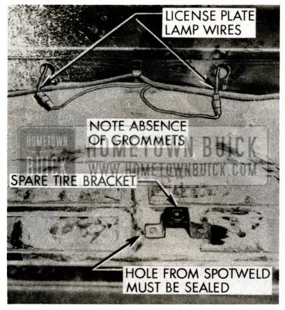
1957 Buick Licence Plate Lamp
Another item that might cause dust to enter through the floor would be the entire seam around the floor pan, particularly between the inner quarter panel and the floor pan; also where the spot welds may be burned through at the spare tire and floor board brackets. See Figure 156 & 157.
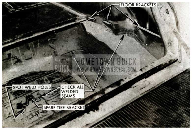
1957 Buick Estate Wagon Rear Compartment Floor
On some cars, the tail lamp wire grommet has too large an opening for the wire allowing dust to enter. Seal the opening around the wire with Auto Body Sealer.
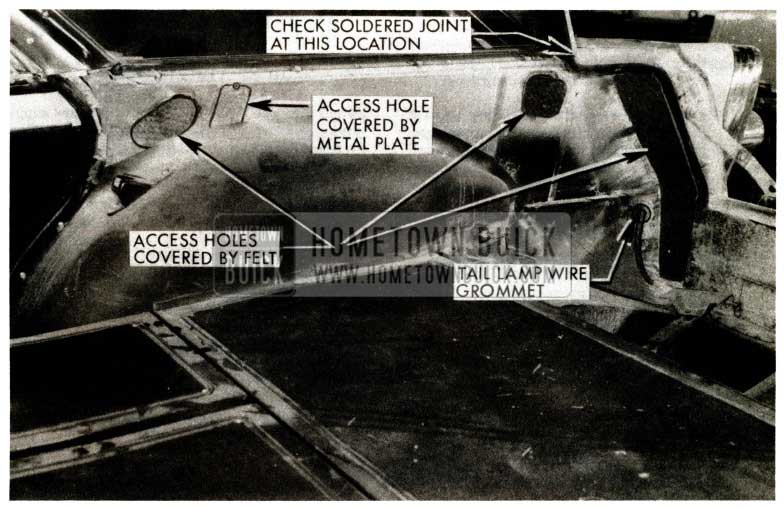
1957 Buick Estate Wagon Rear Compartment
In addition, there is one opening above the wheel house on each side that is covered by a metal plate. This must also be sealed with Auto Body Sealer. See Figure 158.
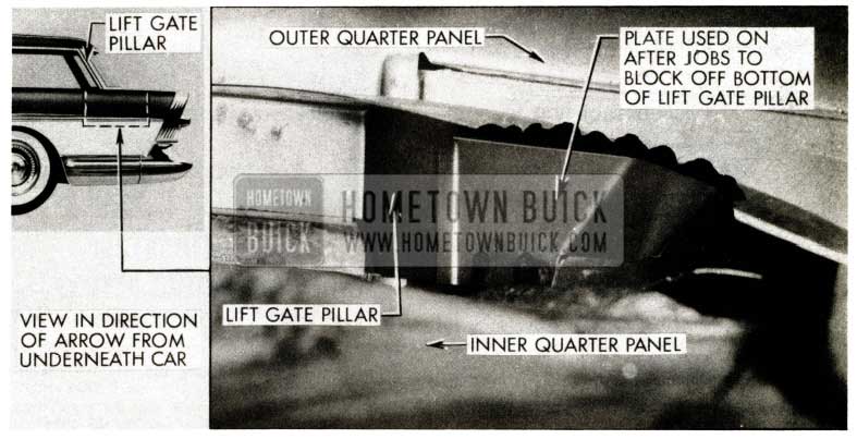
1957 Buick Estate Wagon Lift Gate
SEAT ADJUSTER CONTROL ROD INOPERATIVE
MANUALLY OPERATED SEATS
1957 Buick
lf manually operated seat adjusters are encountered on which the right seat adjuster does not unlock due to slack at the control rod-to-right seat adjuster attachment, the control rod should be crimped as described below:
- Remove seat assembly with attached seat adjusters from the body and place up side down on a clean surface.
- Insert a wedge under control arm of right seat adjuster, as indicated in Figure 160.
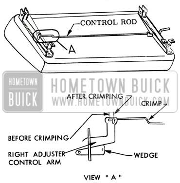
1957 Buick Seat Adjuster Control Rod
OPERATION OF REAR WINDOW
All 1957 Convertible Models
Damage to a convertible top rear window zipper often results when the proper procedure as outlined in the folding top booklet is not followed when raising the rear window to the closed position. The procedure as outlined below eliminates the possibility of placing an excessive strain on the zipper.
LIFT THE WINDOW AND HOLD IT IN ITS APPROXIMATE CLOSED POSITION IN THE OPENING, THEN SLIDE THE ZIPPER ALONG THE SIDES AND TOP OF THE WINDOW.
NOTE: In some instances the rear window zipper can be operated easier if the top is released at the windshield to relieve the tension on the zipper.
ASH TRAY CHANGE
1957
Several dealer product reports have been received stating that the openings in the ash trays were too small and that it is difficult to deposit ashes in them without getting some ashes on the floor. If more room is desired, it may be obtained by bending the outer tabs into the ash tray as shown in Figure 161.
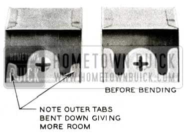
1957 Buick Ash Tray Change
RELOCATING FRONT DOOR WEATHERSTRIP
1957 Buick – All Models
If a condition is encountered where the front door hinge pillar weatherstrip is being damaged due to contact with the lower instrument panel attaching screw on the front body hinge pillar, the upper portion (approximately 8 inches) of the weatherstrip may be relocated outboard 1/2″ to correct the condition.
- Carefully remove the upper weatherstrip fastener and break cement bond along upper portion of auxiliary weatherstrip.
- Clean off original weatherstrip cement from door hinge pillar. Mark new weatherstrip location on door hinge pillar 1 /2′” outboard of weatherstrips original location.
- Apply an approved weatherstrip cement to the new weatherstrip location on the door hinge pillar, and to the weatherstrip cementing surface; then’ install weatherstrip.
- To improve the attachment of the weatherstrip, two (2) additional fasteners Gr. 10.695 Part #4653672 may be installed at locations indicated by “B” in Figure 162.
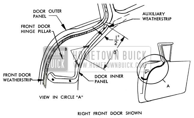
1957 Buick Front Door Weatherstrip
To provide attachment for the fasteners, drill two (2) 1/8” diameter holes through the weatherstrip and hinge pillar at fastener locations.
INSTRUMENT PANEL CENTER OUTLET WARPING
1957 Air Conditioner Models
We have received several dealer Product Reports which state that the corners of the air conditioner center outlet are warping causing an unsightly appearance at this area. This condition may be corrected by drilling with a #32 drill in each of the four (4) corners of the outlet and installing a metal screw # 8 by 1/2” long to hold the corners from warping outward.
SHARP CORNERS ON MOLDING
1957 Buick – All Models
If a condition is encountered where the rear lower corner of the windshield side garnish molding is sharp and protrudes from the windshield side pillar, the following procedure may be performed to correct the condition:
- If the garnish molding is not installed properly, remove molding attaching screws and reposition molding as required.
- Using a fiber block and hammer, carefully rework corners to re move protruding sharp edges. In some cases, it may be necessary to file off sharp edges.
- Touch-up reworked area as required.
LAMP SOCKET CLEARANCE
1957 Buick – Models 46C And 66C
On some early production bodies, insufficient clearance may exist between the left or right folding top compartment side trim panel courtesy lamp socket assembly and the body lock pillar to floor pan brace causing frayed or worn insulation to the courtesy lamp socket wires. If this condition is encountered, it can be corrected by drilling a clearance hole in the brace for the socket assembly as follows:
- Disconnect battery cable.
- Remove ash receiver from escutcheon in side trim panel and mark location of pilot hole to be drilled in floor pan brace directly behind the socket assembly.
- Carefully squeeze top and bottom of courtesy lamp lens together and remove lens from lamp assembly.
- Remove two (2) screws securing the lamp assembly to the folding top compartment side trim panel assembly.
- Carefully bend both lamp assembly reta1mng tabs forward to allow clearance for a one (1) inch drill.
- Drill a one-quarter (1/4) inch pilot hole in the floor pan brace at location previously marked and then complete the drilling operation with the one (1) inch drill.
- Tape the edges of the hole to cover any existing burrs incurred in the drilling operation.
- Check wire insulation at socket assembly and, if damaged, repair as required.
- Carefully bend both lamp assembly retaining tabs rearward into position and install lamp assembly.
- Install all previously removed parts.
NOTE: Current production bodies incorporate the necessary clearance in this area.
REWORKING REAR QUARTER BELT MOLDING
1957 Buick – Model 48
If a condition is encountered where the body lock pillar windlace is being cut by the front edge of the rear quarter belt finishing molding, the condition may be corrected by reworking the front edge of the molding as follows:
- Remove rear seat cushion and back; then remove rear quarter belt finishing molding.
- Cut molding along corner shown in Figure 163, sufficiently to allow 1/8” of the front end to be bent over; thereby shortening the molding.
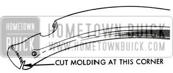
1957 Buick Rear Quarter Belt Molding
WINDSHIELD WIPER SERVICE INFO.
Following is a reprint of Red Band Special Service letter, Dealer No. 193, dated December 7, 1956.
We have received a number of dealer Product Reports on 1957 Cam -0-Matic windshield wiper operation with specific complaints directed to stalling, noisy and slow operation. Wiper service information furnished in this letter will, therefore, pertain mostly to Cam-0-Matic type wiper installation; however, Steps three (3) through seven (7) are applicable to non Cam-0-Matic jobs as well. The operation of both type windshield wipers should, however, give smooth, noiseless and free operation on wet glass, and no hesitation or erratic action should exist.
Approximately March 11, 1957, new windshield wiper cams, Gr. 10.147 Part 4726069 Rt. and 4726070 Lt., went into production which greatly improves windshield wiper blade cleaning action.
The design of the new cams provide smoother wiper blade operation and a slightly wider arc travel. If complaints of poor erratic wiper blade action are encountered, it is suggested to replace the cams before attempting any major repairs on the windshield wipers, motor or transmission as outlined in the following procedure.
Identification of the old and new type cams can be seen in Figure 164.
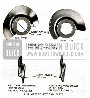
1957 Buick Windshield Wiper Cam
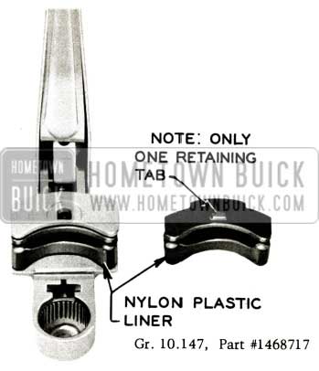
- Examine Cam-0-Matic wiper black nylon plastic guide which rides on cam plate to see if it is worn, cracked or otherwise damaged. See Figures 166 and 167. If plastic guide Gr. 10.147, Part #1468717 is defective, it must be replaced.
NOTE: The new black nylon plastic liner has one retaining tab for holding it in place. See Figure 165.
1957 Buick Windshield Wiper Retaining Tab
The Parts Department advises that they will not replace for service the liners with two retaining tabs as only 1200 of this type were used. If a replacement is needed on a wiper arm with the liner that has two retaining tabs, on any of the 1200 arms used, it will be necessary to replace the arm. It is advisable to lubricate cam plate and guide with DC 4X Silicone Lubricant or equivalent.
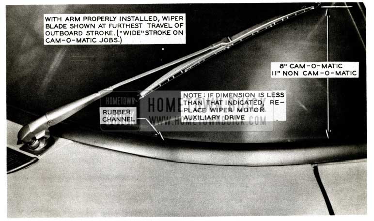
- Make certain that each wiper arm is fully seated on end of transmission shaft. If splines on end of wiper transmission shaft are visible underneath wiper arm, it indicates that arm is not fully seated. To properly seat wiper arm insert a screwdriver blade under spline end of shaft and rotate blade to move spline shaft into wiper arm until they are no longer visible. See Figure 166.

1957 Buick Windshield Wiper Arm Adjustment
NOTE: Wiper arm must be fully seated on end of transmission shaft; otherwise, a ratcheting condition of the drive pulleys will result.
1957 Buick Windshield Wiper – Arm
If distance is less than that specified, the windshield wiper auxiliary drive should be replaced with the following:
Cam-O-Matic Auxiliary Drive Gr. 10.157 Part #4 716685
Non Cam-O-Matic Auxiliary Drive Gr. 10.157 Part #4 716598
On Cam-0-Matic equipped jobs, the windshield wiper motor auxiliary drive pulley should have a diameter of 1.94″ which is identified by a “1.94” stamped on face of pulley. NOTE: The auxiliary drive on non Cam-O-Matic jobs should have a “1.76” stamped on face of pulley, indicating diameter of same. See Figure 168.
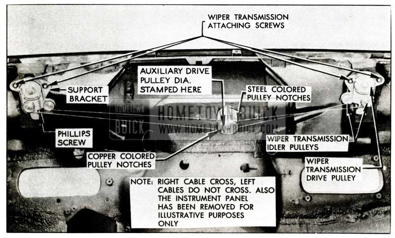
1957 Buick Windshield Wiper Transmission Attaching Screws
- Make certain vacuum hoses are properly connected at check valve at wiper motor, washer bottle, intake manifold pipe, vacuum pump line connection at rear of block, and connector at intake manifold.
- With engine idling at 485 RPM, check intake manifold vacuum with vacuum gauge connected to hose at check valve on wiper motor. Gauge should indicate minimum of 13.5″ hg.
- Disconnect vacuum pump line (hose) from check valve and connect vacuum gauge to hose. Run engine at 1600 RPM and observe vacuum reading. Gauge should register minimum of 22″ hg. at 1600 engine RPM. If a reading less than 22″ is obtained, replace the vacuum section of the vacuum oil pump assembly. NOTE: A faulty vacuum pump will give poor wiper action under wide open throttle conditions at low car speed.
- If vacuum pump is okay, re move each wiper blade arm and operate engine at idle speed. Operate wiper transmission at wide stroke and check the wiper transmission shaft for binds. This is accomplished by grasping the spline end of the shaft and moving it in and out approximately 1/4″. If a bind is present in the shaft, the wiper transmission should be replaced using the specific installation procedure in Step 9. If a bind cannot be detected, remove upper instrument panel (center section) and perform the following additional checks:
- Make certain wiper cables are free from interference with wiring and other dash components and that wiper motor auxiliary drive pulley is not rubbing against cowl panel. Auxiliary drive may be adjusted to the upward position to correct binding, or if necessary, the cowl panel opening may be enlarged if required.
- Check for evidence of wear or interference between the drive pulley tab and pulley guard. See Figure 169.
1957 Buick Windshield Wiper Drive Pulley
If evidence of rubbing exists at this point, replace the wiper transmission using the procedure outlined in Step 9.
1957 Buick Windshield Wiper Exploded View
Tighten inner spanner nut and check for interference of transmission shaft and cow1 outer panel. File cowl outer panel for clearance if necessary. Then install outer spanner nut. See Figure 170.
1957 Buick Windshield Wiper Transmission
The following are group and part numbers of Cam-O-Matic wiper transmission involved. Parts Warehouses should have these items in stock by the time this letter is received.
Series 50 and 70 – Right Gr. 10.159 Part #4716589
Series 50 and 70 – Left Gr. 10.159 Part #4716593
Series 40 and 60 – Right Gr. 10.159 Part #4 716590
Series 40 and 60 – Left Gr. 10.159 Part #4 716594
REAR DOOR WINDOW CENTER GUIDE SHOE ASSEMBLY
1957 Buick 43 & 63 Models
lf rear door window rattles are encountered on models 43 & 63 due to insufficient tension of the rear door window center guide shoe against the center guide, the condition may be caused by the long center guide shoe spring. See Fig. 172.
1957 Buick Rear Door Window Center Guide Shoe
SQUEAKS AT INSTRUMENT PANEL
1957 Buick – 40-60 Series
If squeaks are encountered between the outer lower ends of the instrument panel, and the upper end of the shroud side trim panel retainer, the condition may be corrected by cementing a piece of 3/4″ x 1/2″ x 1/8″ tacking strip to each end of the instrument panel as outlined below.
- Remove each shroud side trim panel.
- Remove screws securing each shroud side trim panel retainer and remove retainers.
- Cement a 3/4″ x 1/2″ x 1/8″ tacking strip or equivalent material to each end of instrument panel as indicated in Fig. 173.
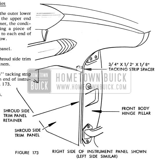
1957 Buick Instrument Panel Right Side
BODY SERVICE MANUAL REVISIONS & CORRECTIONS
The following revisions and corrections should be made in your 1957 Body Service Manual in order to bring it up to date.
NOTE: For your convenience, the figure number references are the same as those used in the Body Manual.
Due to a change in the windshield lower reveal molding outer clip, located outboard of the wiper transmission, it is necessary to loosen the rear upper corners of the front fenders to gain access to the reveal molding clip attaching screw shown in Fig. 13-4 on Page 13-4 and Fig. 13-164 on page 13-108 of the 1957 Body Service Manua1.
1957 Buick Windshield Clips
The following revisions should be incorporated in the Windshield Lower Reveal Molding Removal and Installation Procedures located on page 13-4 of the 1957 Body Service Manual.
Revise steps (d) and (e) of the procedure as follows:
- Loosen the rear upper corner of each front fender sufficiently to gain access to the molding clip attaching screws located outboard of the wiper transmission. See Fig. 13-4.
- Remove both outer clip attaching screws; then slide each lower reveal molding outboard to disengage it from the remaining molding attaching clips.
Delete step (f) from the procedure and locate the “NOTE” beneath the revised step (e). Re-letter step (g) to step (f).
The following revisions should be incorporated in the Windshield Lower Reveal Molding Removal and Installation Procedures located on page 13-108 of the 1957 Body Service Manual.
Revise step (d), (e) and (f) of the procedure as follows:
- (d) Remove screw from lower reveal molding attaching clip which is readily accessible with the door open.
- Loosen the rear upper corner of each fender sufficiently to gain access to the molding clip attaching screw located immediately outboard of the wiper transmission.
- Remove clip attaching screw; then slide each lower reveal molding outboard to disengage it from the remaining molding attaching clip. See Fig. 13-164.
On Page 13-17 and 13-18, Paragraph 13-6, Sub Paragraph; g and h have been revised as follows:
Removal of Door Water Deflectors
On all body styles a waterproof paper (wax impregnated) door inner panel water deflector is cemented to the front and rear edges of the door. The water deflector which covers the door inner panel, fits into a slot along the bottom of the door inner panel and deflects water into the bottom of the door where it can drain out the door bottom drain holes. Whenever any work is performed on a door where the water deflector has been disturbed, the deflector must be properly sealed and cemented to the door inner panel.
The following procedure for servicing a door inner panel water deflector covers detachment of deflector for access to door inner panel, and removal and installation of deflector.
- Remove door belt finishing molding and door trim assembly.
- Remove trim assembly retainer tabs and arm rest hanger plate, where present. Remove strips of body tape securing upper and lower corners of water deflector to inner panel.
- To detach water deflector, for access to door inner panel, carefully cut deflector from top to bottom inside either the front or rear cemented edge of deflector. See Figure 13-26.
1957 Buick Door Water Deflector
IMPORTANT: Cut or cuts should be straight and located over portion of inner panel with the least depressions to facilitate effective application of water-proof body tape when reattaching deflector.
The following Figures 13-61, 13-194 and 13-217 taken from the Body Service Manual are being reprinted to show corrections.
1957 Buick Door Window Right Frame
Figure 13-61 and 13-217 should have a 3/16″ clearance on the side roof rail weatherstrip to be properly aligned with the door window upper frame, and the front and rear door window frame should have 1/4” clearance on the weatherstrip.
Figure 13-194 should be corrected to show two (2) hinge strap cover plate attaching screws instead of one.
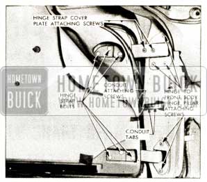
1957 Buick Hinge Strap
Will you please make the above corrections in your 1957 Body Service Manual.
In addition to the above changes, on Pages 13-91 the captions “Up and Down Rear Edge Solenoid” and “Fore and Aft Solenoid” shown in Figure 13-135 of the manual are reversed. We are therefore reprinting the figure showing the correct location of the two solenoids.
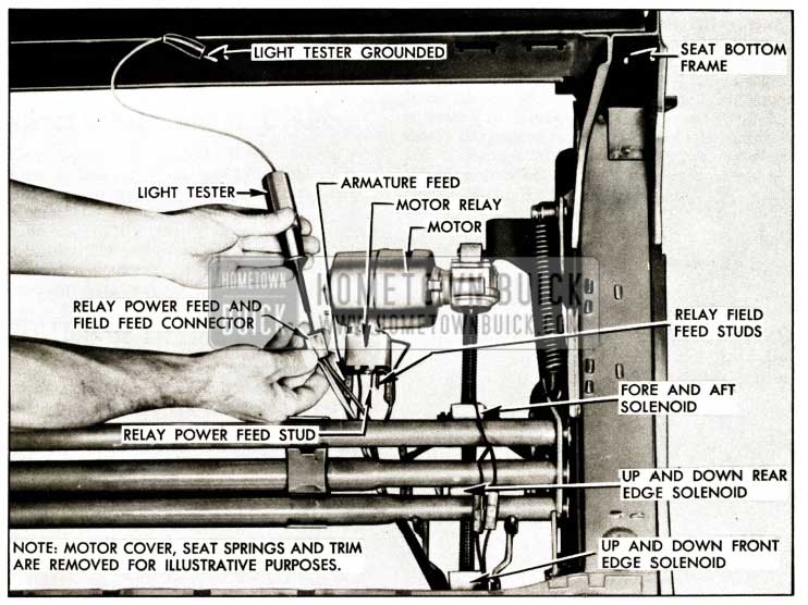
1957 Buick Selenoid Locations
Leave A Comment
You must be logged in to post a comment.