INSTRUMENT PANEL CENTER AIR OUTLET CAMPAIGN
Following is a reprint from Special Service Letter – Dealer No. 206, dated April 8, 1957.
SUBJECT: Center Instrument Panel Air Outlet Change – 1957 Air Conditioner Equipped Cars
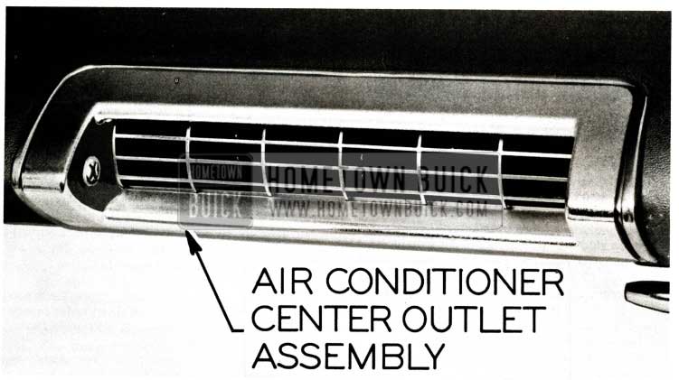
In order to provide a more satisfactory appearance, it has been decided that all 1957 Air Conditioned Buicks equipped with the first type center outlet having three (3) vertical fins will be campaigned to incorporate the new chromed outlet shown in Figure ll5.
1957 Buick Air Conditioner Center Outlet
All Factory-installed Air Conditioner equipped Buicks having serial numbers lower than those listed below by Assembly Plants are to be campaigned, including those Air Conditioner packages installed by dealers.
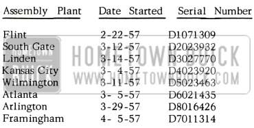
1957 Buick Air Conditioning Packages Cars
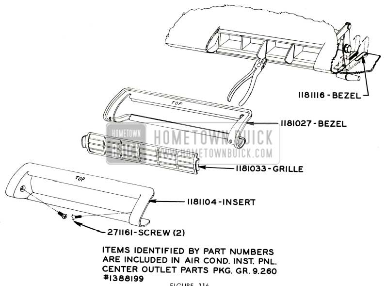
Air Conditioner Instrument Panel Center Outlet Parts Package, Gr. 9.260 #1388199 shown in Fig. 116.
1957 Buick Air Conditioner Center Outlet Assembly
Flat rate time for installing the center outlet is beginning to be made available at all parts warehouses the week of April 8th; therefore, it is suggested that dealers immediately place orders for them so that this program may be concluded as quickly as possible.
In the very near future, each dealer will receive from the zone office, I.B.M. car record cards bearing serial numbers of Factory installed units requiring this campaign, plus a count of the number of package units purchased from the field warehouse. It is requested after the new chromed center instrument panel air outlet has been installed according to the procedure outlined below that the car record card on the Factory- installed units be attach d to the corresponding AFA for each job campaigned. Obviously, this cannot be done where a dealer installed air conditioner equipped job is campaigned; therefore, in such instances submit AFA’s in normal manner.
To install the above mentioned package, the following procedure is recommended:
- Remove center outlet plastic grille from upper instrument panel.
- Using a pair of diagonal cutters, cut out the three (3) fins from the center outlet casting as shown in Figure 117.
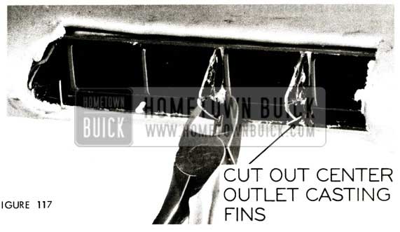
1957 Buick Air Conditioner Center Outlet Fins
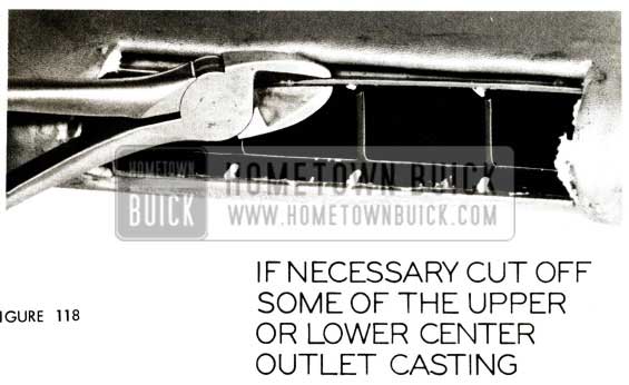
1957 Buick Air Conditioner Center Outlet Casting
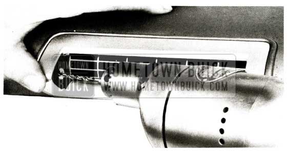
1957 Buick Air Conditioner Center Outlet Fixing
Complete assembly should fit snugly to prevent the grille from rattling against the bezel or insert.
Flat rate time for installing the center outlet package is .9 hr.
The new center outlets should be installed on cars requiring this change first. Each dealer should then order a new center outlet Parts Package for each Air Conditioner Installation Package, Gr. 9 .169
Part 981849, that he now has in parts stock and use it in place of the first type outlet when the Air Conditioning Package is sold and installed on a car.
Every effort should be made by all dealer personnel to get the cars requiring this campaign in so that it may be brought to a swift conclusion.
COMPRESSOR NOISE & VIBRATION
Following is a reprint of Special Service Letter – Dealer No. 207, dated April 5, 1957:
SUBJECT: Air Conditioner Compressor Noise and Vibration
During the past few weeks we have been receiving an increasing number of product reports on compressor noise and vibration on 1957 Air Conditioner equipped Buicks. Since there are several factors to consider on an Air Conditioner equipped car in diagnosing vibration and noise complaints this bulletin has been prepared to help pinpoint the source of trouble with the minimum amount of time and effort.
Before attempting diagnosis of the above mentioned complaints, the Air Conditioner should be in complete operation with blower set at “low” position. Doing so will provide proper circulation of refrigerant through the compressor and evaporator, thereby permitting analysis under normal operating conditions.
Compressor noises may be classified as follows:
- Cold Noise – Under low operating temperatures (below 70° F) when the Air Conditioner is used for dehumidification, an inherent compressor shaft end play noise may be heard. This is caused by the low head pressure existent under such conditions and should not be confused with the noise due to a broken valve reed as described in the 1956 Abridged Edition of BPS Bulletins, Page 11 7. “Cold noise” heard under these conditions is normal and no attempt should be made to remove it. To determine if the noise in question is “cold noise” place a piece of cardboard in front of the condenser and operate the Air Conditioner for a short period of time. By obstructing air flow through the condenser in this manner, high head pressures will develop in the compressor and the noise will disappear. This may be demonstrated to the owner and an explanation given to the effect that higher temperatures within the compressor causes expansion of internal components and an initial compressor shaft end play is necessary to compensate for it. If this end play were removed, subsequent compressor failure would result.
- Discharge reed valve noise -This is a “growl” type noise which is generally heard throughout the compressor operating range up to approximately 45 MPH and is more pronounced with compressor engaged and engine idling. This condition may exist on compressors bearing serial numbers lower than 44GC002 and may be reduced by installing a new discharge valve plate, Gr. 9.172 Part #5913872, as described in BPS Bulletin 2.419, Page 85.
- Vibration noises – Several reports have been received stating that a slight vibration exists on light acceleration up to approximately 30 MPH and is present with compressor disengaged. This is an indication that the source of difficulty is not in the compressor; however, due to the additional weight and mounting of the compressor, part throttle roar noises are magnified. Some relief may be gained by making certain that rubber refrigerant hoses and power steering hoses are not bearing heavily against chassis sheet metal, windshield washer bottle unit, or body toe board seam, and that hoses are not twisted, in which case they become more rigid and tend to transmit vibrations. After these items have been eliminated as possible source of trouble, and the roar persists, it may help to completely loosen and realign the entire exhaust system.
- Generator bracket contacting fender skirt – On some early production jobs the clearance between the generator bracket and fender skirt was very close and in some instances when the engine is under load, metal to metal contact is made. If this condition is found to exist, pry sheet metal away from bracket to provide adequate clearance.
- Generator Vibration – If generator vibrates enough to be heard in the car, it will vibrate enough to be felt by hand. As the engine RPM is increased the generator may go into periods of vibrations at different intervals. Make certain that generator mounting and belt tension brace bolts are securely tightened. After it is determined that the generator mounting is OK and the vibration persists, try another generator.
- Other sources of vibration which may be magnified by the increased weight of the Air Conditioner are covered in 1956 Abridged Edition of BPS Bulletins, Page 7. Your attention is particularly directed to the “Body” section on Page 9 which describes body mountings.
- If compressor operation is still abnormally noisy after performing the above procedure, replace the compressor.
FUNCTIONAL TEST – 1957
The following functional testing data is to be used when checking 1957 air conditioner equipped cars.
Car conditions for functional test are:
- No sun load
- Hood closed
- Doors open
- Heater Ranco valve off
- Hot gas valve set for maximum cooling
- Forced draft, approximating 10 MPH wind on condenser if ambient temperature is below 80° F.
Each car in which the unit has been repaired or recharged should be tested in accordance with the following ”Functional Test Data”:
NOTE: Set Engine Speed as designated for each corresponding ambient temperature.
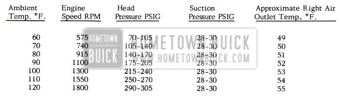
1957 Buick Compressor Functional Test
NOTE: All air conditioning units are shipped charged with 5.0 pounds of Freon 12. This is a full charge and precaution should be taken to charge no more than this quantity for a recharge after repair.
NOTE: Conditions of high relative humidity tend to lower the efficiency of the unit since no cooling effect is derived from the cold water which drains out of the evaporator. Thus, some variation in suction pressures and outlet temperatures should be expected with variations in humidity.
If it is evident during the functional test that it is necessary to adjust the “Hot Gas By-Pass Valve” to correct the suction pressure, the following procedure is to be used:
- Disconnect the valve control cable.
- Remove the valve control lever, return spring and nylon cam follower.
- Set engine speed as determined by ambient temperature.
- Turn slotted screw in valve spring sleeve in or out with a reworked screw driver to give a 28-30 pound pressure on the suction pressure gauge.
- Reassemble parts and adjust control cable.
AIR CONDITIONER SERVICE INFO.
Suggested Procedure For Pre-Season Check-Up Of Buick’s Air Conditioning System
In the 1957 Owner Manual it is recommended that the owner operate his air conditioning for a few minutes periodically during the winter months to lubricate the internal compressor seal and thus prevent possible loss of refrigerant. We also suggest that the owner have the air conditioning checked each spring in preparing for summer operation. For this reason the following procedure is suggested for pre -season checkup of 1957 Buick Air Conditioning Systems, including those of past models.
- Clean the external surface of the condenser. Use water and a stiff bristle brush, or blow clean with an air hose. DO NOT STEAM CLEAN. Be certain that radiator air passages are not restricted.
- Clean the external surface of the evaporator (cooling coil) by flushing with water or suitable detergent solution. Check to be certain the condensate drain is open. See BPS 2.405.
- If the system is equipped with a filter in the air path, remove, inspect, clean or replace. Check blower operation and air flow.
- Check, and tighten if necessary, all electrical terminals in the air conditioning wiring.
- Check, and tighten if necessary, the compressor mounting brackets and bolts.
- Inspect the compressor belt or belts. If worn, frayed or damaged, replace. Adjust for proper tension.
- If the system is equipped with flexible hoses for refrigerant lines, make the following inspections:
- Signs of any damage or wear.
- Evidence of leaks.
- Proper support of hoses.
- If any sub -standard conditions are noted – replace affected part.
- Check compressor oil level – replenish if necessary.
- Connect a high and low pressure gage set to the proper fittings. Observe the pressures in the system. Be certain that service valves are correctly positioned before operating unit.
- Use a Halide torch, or suitable method, to leak test the entire system. Correct any leaks that are found. Evacuate and re-charge system.
- Operate the engine at a speed of approximately 1500 RPM, or an equivalent of 30-40 MPH road speed.
- Turn the air conditioning control to the “ON” position. Turn the blower fan control to the “HIGH” position.
- Check for proper engagement and release of the compressor clutch by alternately opening and closing the electrical circuit.
- Observe sight glass to be certain that there is a solid column of clear liquid under operating (maximum cooling) conditions. Add Freon if necessary.
- Continue to operate the engine for 10-15 minutes to allow the system to balance out. Perform functional test.
- If the system is equipped with a solenoid by-pass or hot-gas by-pass valve, check for proper control, while the engine and compressor are operating.
NOISY AIR CONDITIONER COMPRESSOR
(1956 & 1957 Models)
For your information if noisy air conditioner complaints are reported on either 1956 or 1957 compressors up to Serial #44GC002 and no other apparent malfunction can be found such as broken reeds, warped plate, etc. as outlined in the 1956 Air Conditioner Service Information Bulletin which was attached to BPS 2.412 dated September 15, 1956, the noise may be reduced by installing a new 1957 discharge valve plate, Gr. 9 .172 Part #5913872.
The use of the 1956 discharge valve plate, Gr. 9.172 Part #5912672 is not recommended for correcting noise complaints on 1956 compressors. If, however, the discharge valve plate is defective and the compressor is not noisy, then only should the 1956 plate, Part #5912672 be used.
COMPRESSOR HEAD BOLT TORQUING
1957 Air Conditioner
We have received a few reports that service personnel are over-torquing the compressor head bolts on 1957 Air Conditioner equipped cars. In one particular case the bolts were torqued so tight that the compressor cylinder block was distorted.
The proper method of installing the compressor head is outlined in the 1957 Service Manual, Step 8, Page 11-29 as follows:
When the head is properly aligned with dowel pins, assemble all twelve cylinder head bolts so they are only FINGER- TIGHT. An initial torque of 3 to 5 ft. lbs. should first be applied to opposite bolts all around compressor head and then tighten in same sequence to specified 7 1/2 to 10 ft. lbs.
NOTE: The procedure of tightening and torqueing these bolts is very important. If uneven or excessive torque is applied it will distort various parts and may decrease the end clearance of the shaft and cause a compressor failure because of burned thrust washers.
ADDING OIL TO COMPRESSOR
1957 Buick Air Conditioner Oil Adding Procedure
Only if it has been determined that a considerable quantity (4 oz. or more) of compressor oil has escaped from the system and checking the oil level at the fitting provided indicates a lack of oil in the compressor reservoir, the following procedure should be followed:
- Discharge remaining Freon from the system.
- Remove compressor and drain oil reservoir into a clean container.
- If oil is clean proceed with Step No. 4; if oil is dirty, flush both compressor and condenser with liquid Freon until clean.
- Pour 9 oz. of new 525 viscosity Frigidaire compressor oil into compressor through oil checking fitting.
- Reinstall checking screw and reinstall compressor.
- Connect all hoses and fittings, evacuate and charge with Freon 12 at tank pressure and leak test.
- Evacuate, charge with 5 lbs. of Freon 12 and perform functional test.
CLIP INTERFERENCE WITH DISCHARGE LINE
1957 AIR CONDITIONED CARS
Interference between the discharge line on some 1957 Air Conditioner equipped cars and the generator wiring harness clip on the right front fender skirt has been reported. To correct this condition the clip should be rotated 180° so that it points downward; also, the discharge line to liquid line grommet clamp should be loosened and the discharge line pulled forward to provide a minimum of 3/4 inch clearance to the fender skirt.
The above correction has been made in production.
INSULATION OF HEATER-DEFROSTER CORE HOUSING
Air Conditioner Equipped Cars
It has been brought to our attention that some dealers when installing air conditioner field insulation packages are not insulating the outer heater defroster core housing. This practice, is almost certain to result in customer dissatisfaction, as the cooling efficiency is greatly reduced. Laboratory tests show that approximately 5° of cooling is lost if the housing is not properly insulated.
Leave A Comment
You must be logged in to post a comment.