CLOCK FUSE CHANGE
1957 – All Series
It has been found on one make of clock that if the glove compartment door is slammed excessively when the clock is in a certain stage of unwind, it is possible for the contact points to close without winding the clock. When this occurs with a two-ampere fuse in the circuit, the fuse link inside the clock case opens up to prevent the clock winding coil from being damaged. When a one-ampere fuse is used in the clock circuit and the contacts close due to a severe impact, the one-ampere fuse will blow, protecting the internal fuse and winding.
Since it is much easier to change the fuse in the fuse block than to repair the internal fuse in the clock, we are changing to the use of a one ampere fuse.
When a clock or clock fuse is replaced, a oneampere fuse (1 amp. AGA or 1 AG) Gr. 8.965 Part #149559 should be used.
SEAT BELT
1957 Model
The present Seat Belt Packages, Group 14.875 Parts 981773, 981774 and 981775, may be used on 1957 Models although the mounting locations are changed slightly from those used in 1956. New 1957 instruction sheets have been added to all stock of these Seat Belt Packages in the warehouses and any shipments received from your warehouse after February 1 will include the 1957 installation instruction sheet as well as the 1956 installation instruction sheet.
NOISY REAR COMPARTMENT SPEAKER
Many of the speakers returned to the Factory are damaged during shipment to the extent it is difficult to ascertain whether or not speaker when received is in the same condition as when removed from the car. In the future please package defective speaker in carton in which new speaker was packaged; otherwise, credit will not be allowed.
Also, many speakers returned as being noisy are found to be satisfactory. Your attention is directed to the fact that if the two (2) wires leading from speaker cone to coil touch the magnet or speaker frame it will cause the speaker to be noisy . This condition, however, can be corrected by repositioning the wires to provide clearance. Before condemning the speaker, check it for noise by attaching jumper wires and holding the speaker by hand and listening for noise while radio is playing. If wire clearance is satisfactory and noise persists, replace speaker. Package defective speaker (with parts return tag properly filled out) in carton as previously explained and return to the Zone with other warranty material.
WINDSHIELD WASHER HOSE INSTALLATION
We have received reports whereby dealer personnel, when filling windshield washer bottle on 1957 Buicks, inadvertently installed the water outlet hose on the vacuum outlet and vice versa. In each case water from the bottle was pumped in engine crankcase, necessitating draining the crank case.
It is, therefore, suggested that the service men carefully check the water and vacuum hose to make sure they are installed properly. Figure 105 shows the correct position of the hoses.
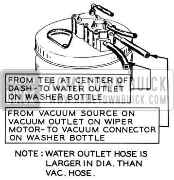
1957 Buick Windshield Washer Hose Installation
MOUNTING COMPASS
On 1957 Model 50-70 Series
A special extension bracket is being made available for use when mounting Gr. 8.875, Part 1981827 Compass on the 1957 Model 50-70 Series. The present bracket should be used when mounting the Compass on all 40-60 Series using the mirror bracket screw for mounting as shown on the Compass Instruction sheet. The new extension bracket should be add d as shown in Fig. 106 when mounting the Compass on the 50-70 Series, using the garnish moulding screw to the right of the mirror bracket for attachment.
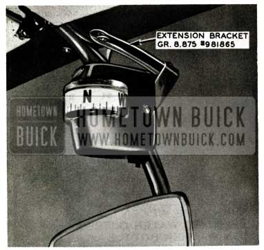
1957 Buick Compass Mounting
All shipments of Compasses made from the warehouses after February 11 will include this new extension bracket and screw. Any Compasses you have in stock may be used on 50-70 Series by adding this extension bracket which may be ordered no charge from the following address:
Parts & Accessories Merchandising Dept.
Buick Motor Division
Flint 2, Michigan
Order your requirements on this bracket as follows: Group 8.875, Part 981865 Bracket-Compass Mounting. (Includes Screw)
IMPROVED HEATER PERFORMANCE
All 1957 Cars
We have been advised that some early production 1957 cars had deficiencies which could result in the following complaints:
- Insufficient volume of air coming out of the right heater air outlet.
- Heater air temperature control not operating properly.
Excessive vibration from heater blower.
On complaints of insufficient volume of air coming through the right air outlet, it is suggested to check the air hose running from the inner heater housing to heater distributor duct, also hose running from distributor duct to right air outlet, to make sure there are no kinks or bulges as shown in Figure 107.
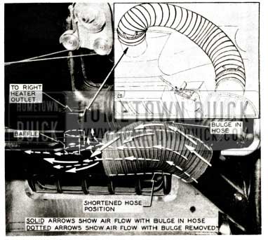
1957 Buick Heater Performance
A bulge in the air outlet hose will deflect the air stream under the distributor duct baffle, thus allowing most of the air to pass to the left instrument panel air outlet and very little to the right outlet as indicated by heavy arrows.
To correct this condition, cut one (1) inch off air hose running from inner heater housing to heater distribution duct and two (2) inches off air hose running from heater distributor duct to right instrument panel air outlet. When reinstalling hoses, connect ends so that bulges or kinks are removed. When hoses are free of kinks and bulges the air stream passing through distributor duct will strike the baffle at the desired angle to equally distribute air to both right and left instrument panel outlets. CAUTION: After jobs will have shorter hose lengths; therefore, before doing any cutting of hoses make certain they have excessive lengths, indicated by kinks or bulges as shown in Figure 107.
Heater temperature control not operating properly has been caused by improper installation of heater temperature control capillary in the heater housing duct. To correct this condition remove the glove box and disconnect heater air hose at inner heater housing so that the heater temperature control capillary is visible inside the housing. The capillary is located in forward upper area of duct and should be arranged as shown in Fig. 108. On many of the first production cars the loop in the capillary was straightened out and the rubber hose pulled up over the capillary. In this case, the hose should be moved toward the base of the valve and a loop of approximately 1 3/4″ long made in the capillary and positioned as shown in Fig. 108.
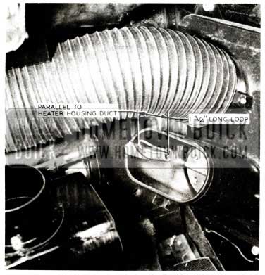
1957 Buick Heater Housing
Excessive vibration from the heater blower is caused by the blower being out of balance. This condition can easily be corrected by adding two (2) extra gaskets, Gr. 9. 784 Part #1170200 under the blower on right ventilator duct.
WINDSHIELD WASHER PUMP CHANGE
We have received reports whereby on cam-o-matic wiper equipped cars the wipers would automatically operate without stopping during freezing conditions. A change was made in windshield washer pump and cover assembly to pre vent this from happening and all pumps identified by an x on the windshield washer pump control valve body shown in Figure 109, have been corrected and are of the late type.
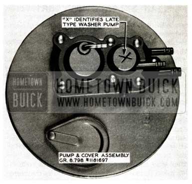
1957 Buick Windshield Washer Pump Change
In order to segregate the change, new part numbers have been assigned and replacements are as follows:
Gr. 8.798 – 981847 Package -Windshield Washer
To be replaced by:
Gr. 8. 798 – 981895 Package – Windshield Washer
Gr. 8.798 – 1175770 Pump & Cover-Windshield Washer
To be replaced by:
Gr. 8.798 – 1181697 Pump & Cover-Windshield Washer
ANTENNA REMOVAL
1957 Models
Following are the instructions for removal and replacement of 1957 Buick antennas:
- Remove left front fender rear skirt outer panel.
- Remove vacuum tank from left shroud on power brake jobs.
- Remove screws holding clamp at bottom of antenna.
- Disconnect antenna lead-in wire from antenna at threaded fitting.
- Remove fuse on electric antennas and disconnect two antenna motor wires at the antenna switch.
- Remove dome nut, adapter, and pad above fender and remove antenna by pulling out beneath fender.
- Reverse above procedure for installation.
NOTE: Occasionally an electric antenna will have to be removed when it has failed or seized in the extended position. If the tube and rod sections are damaged and being replaced, it is then convenient to remove the antenna after first hacksawing these sections off above the dome nut, otherwise, the antenna must be removed with the car on a hoist.
The flat rate time to R &R the antenna is 1. hr. for standard antenna, 1 .4 hr. for power antenna.
REAR SPEAKER INOPERATIVE
1957
We have received several product reports indicating that the rear compartment speaker Gr. 9.665 Part IF981817 only operates when the switch is positioned for both front and rear speakers. This is caused by the switch wires being inserted in the plastic terminal incorrectly. If trouble of this type is encountered in the field, check to make sure the wires are inserted in the terminal correctly.
View A and B in Figure 110 show the incorrect and correct installation of these wires.
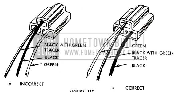
1957 Buick Rear Speaker Cable
To remove the wire and clip from the plastic terminal, it is necessary to insert a small screwdriver in the front opening and depress the retaining tang. The wire and clip will then slide out the rear end of the terminal and can be inserted in the correct location. NOTE: Tang must be bent up before reinserting wire in plastic terminal.
The Parts Department has advised all warehouses to check their stock of rear compartment package 981817. All shipments of this package from ware houses after November 19, 1956, will have the wires inserted correctly in the terminal.
INSTALLATION OF 1957 DOR-GARDS
To insure a satisfactory and correct fit of 1957 model Dor-Gards it is important the following steps be followed in sequence:
Step 1. Loosen Phillips head screw holding molding. Use molding position as locating point. Be certain Dor-Gard follows contour of door at molding location. Press into position at this point.
Step 2. Press Dor-Gard to contour of door per illustration in Fig. 111 until the twisted the portion (approx. 2 inches) remains.
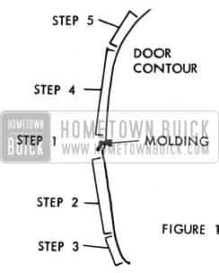
1957 Buick Dor-Gards Installation
Step 3. With one hand hold portion of Dor-Gard illustrated as #2 and with the other hand firmly twist remaining portion of Dor-Gard until Dar -Gard follows contour of door. Press Dar Gard into place.
Step 4. & 5. Repeat same as 2 & 3.
Using rubber or plastic mallet lightly tap Dor-Gard into place.
Be certain Dar -Gard is placed under rubber bumpers if necessary.
It may be necessary to close the ends of the Dor-Gard (pinch together with fingers) to insure a tight fit.
It is extremely important the above steps be followed in sequence.
RANCO VALVE LEAKAGE
1957 – All Series
One of two conditions will cause the Ranco Valve not to be locked out; which will permit heat to flow from the heater on heater jobs or to effect insufficient cooling on Air Conditioner equipped cars.
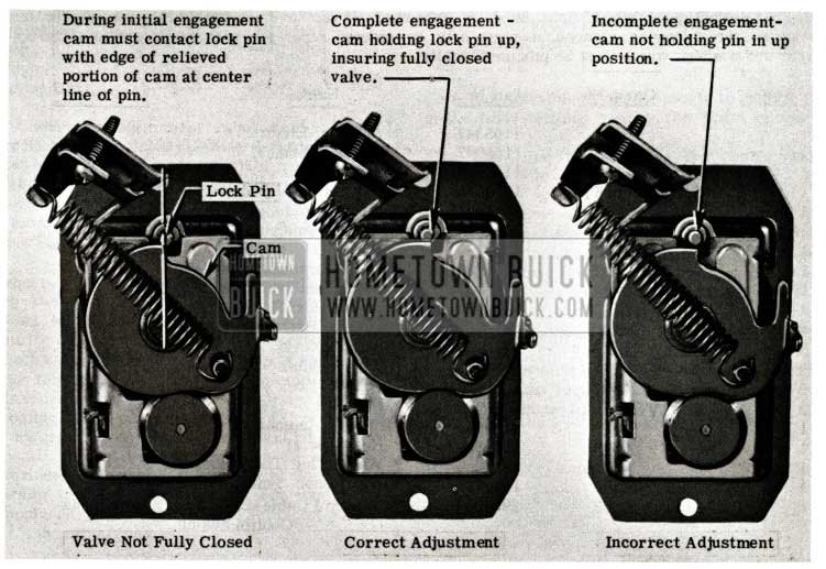
Condition #1: Improper adjustment of the control cable will not fully close the valve, See Fig. 112. To adjust the cable properly, loosen cable clamp at valve, close the valve as shown in Fig. 113, set the control knob 1/16 from the “off” position and tighten the cable clamp. Operate the control to make sure the valve is locked out when the control lever is in the “off” position.
Condition #2: Refer to 1956 BPS 2.412- Page 212. In some cases, the Ranco Valve will operate satisfactorily when the air surrounding the capillary tube is above 70 degrees; however, on Air Conditioned cars when the temperature surrounding the capillary tube is below 70 degrees, the valve does not operate properly, allowing hot water to enter the heater core where it will warm the cool air before it enters the passenger compartment. This is caused by the cool air surrounding the capillary tube condensing or liquifying the gas in the tube, resulting in a loss of pressure on the bellows in the Ranco Valve; consequently allowing the spring to take up the slack in the valve linkage and hold the valve open. See Figure 114.
This may easily be corrected in the car by bending the lock pin on the Ranco Valve “Down” just enough to cause a drag on the cam, or when rotating cam clockwise, the cam overcenter spring snaps the edge of the relieved portion of the cam to the centerline of the lock pin. See Figure 112.
Further movement of the cam to the fully closed position will lock valve closed. See Figure 113. CAUTION: This adjustment should only be made at room temperature or not lower than 70 degrees; otherwise, proper adjustment will not be obtained.
1957 Buick Ranco Valve Leakage
CLOCK REPAIRS
1957 – All Series
It has been called to our attention that some dealers are repairing clocks by re-soldering the safety fuse link when it opens. This safety link is soldered with a special solder having a melting point such that it will release before the clock coil is overheated, and should be repaired only at an authorized clock repair station. Repairs made by dealer personnel voids the warranty, so it is to your advantage to have repairs made by an authorized repair station.
A design improvement was made in the clock the last week in January to eliminate accidental failure of the fuse link. The contact return spring tension was increased four times.
When clocks are repaired at an authorized repair station, this improvement is automatically incorporated.
RADIO & ANTENNA PACKAGES DISCONTINUED
(1956 Manuals and Electric)
The subject packages, Group 9 .645 Part 981709 Manual Antenna and Part 981742 Electric Antenna, will be discontinued when field stock is exhausted. If you have any further requirements for these packages, the following component parts may be ordered separately with the exception of the bolt, screws and washers, which must be procured locally.
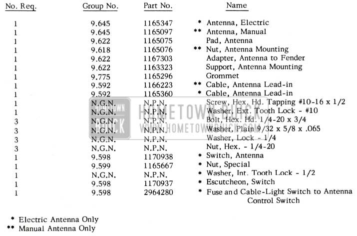
1957 Buick Radio and Antenna Packages
Leave A Comment
You must be logged in to post a comment.